ELMACRON VA/V3 User manual

Water Sampler
VA/V3
v. 2.6

1
TABLE OF CONTENTS
1. INTRODUCTION.......................................................................................................................................................... 2
1.1 CONSTRUCTION......................................................................................................................................................2
1.1.1 Control unit......................................................................................................................................................... 2
1.1.2 Sampling unit...................................................................................................................................................... 2
1.2 PARTS........................................................................................................................................................................2
2. INSTALLATION........................................................................................................................................................... 3
2.1 CASING......................................................................................................................................................................3
2.2 MOUNTING...............................................................................................................................................................3
2.3 ELECTRICAL INSTALLATION ..............................................................................................................................3
2.3.2 Alarm output ....................................................................................................................................................... 4
2.3.3 Connection of a potential free contact (level sensor etc).................................................................................... 4
2.4 CHECKING THE CONNECTIONS ..........................................................................................................................4
3. FUNCTIONS.................................................................................................................................................................. 5
3.1 COMMON FUNCTIONS...........................................................................................................................................5
3.2 OVERFLOW PROTECTION ....................................................................................................................................5
3.3 .....................................................................................................................................................................................5
3.3.1 INTERNAL.......................................................................................................................................................... 5
3.3.2 PULSE ................................................................................................................................................................ 5
3.3.3 ANALOG............................................................................................................................................................. 6
3.3.4 MAX FLOW ........................................................................................................................................................ 6
3.3.5 INTERVAL .......................................................................................................................................................... 6
3.3.6 MAN SAMPLE .................................................................................................................................................... 6
3.3.7 TOTAL SAMPLES............................................................................................................................................... 6
3.3.8 ALARM ............................................................................................................................................................... 6
3.4 KEYS..........................................................................................................................................................................7
4. SETTINGS ..................................................................................................................................................................... 7
4.1 SETTING OF SAMPLING CONTROL.....................................................................................................................7
4.1.1 Internal control................................................................................................................................................... 7
4.1.2 External control .................................................................................................................................................. 8
4.2 ALARM: EMPTY SAMPLE BOTTLE......................................................................................................................9
4.3 INTERRUPT THE SAMPLING ................................................................................................................................9
4.4 START UP THE SAMPLING....................................................................................................................................9
4.5 SETTING THE SAMPLE VOLUME ........................................................................................................................9
5. SAMPLING.................................................................................................................................................................... 9
5.1 SAMPLING SEQUENCE ........................................................................................................................................10
6. MAINTENANCE......................................................................................................................................................... 11
6.1 CLEANING ..............................................................................................................................................................11
6.2 HARDWARE CHECK .............................................................................................................................................12
6.3 CALIBRATION .......................................................................................................................................................12
6.3.1 Pre calibration.................................................................................................................................................. 12
7. TROUBLESHOOTING .............................................................................................................................................. 13
8. SPECIFICATIONS...................................................................................................................................................... 14

2
1. INTRODUCTION
VA/V3 water sampler is designed as an all-purpose unit capable of sampling both contamined and clean water
in all kind of industries.
1.1 CONSTRUCTION
VA/V3 water sampler has a robust, splashproof plastic casing with a transparent front cover.
The water sampler is built up of two units: a microprocessor based control unit and a sampling unit who are
built-in in the same casing.
1.1.1 Control unit
The control unit is microprocessor based. All system parameters are entered/changed with the four pushbutton
keys on the front panel. The LCD-display gives you running information during both programming mode and
sampling sequences.
1.1.2 Sampling unit
The sampling unit consists of a sample bottle, in- and outlet tubes and a built-in compressor/vacuumpump,
which lift the water with vacuum.
All components in contact with the samples are made of non-corrosive material.
The sampling unit is easy to dismount for cleaning (see chapter 6.1).
1.2 PARTS
Please check the parts when delivered.
DESCRIPTION
VA/V3 water sampler
Sample bottle Sample bottle, 300 ml
Tubes Reinforced PVC - tube 16/22.5 ( inlet ) ca 2 m
Silicon tube 12/16 ( outlet ) ca 35 cm
Cables 4-wire cable with Amphenol-contact, ca 2 m
2-wire contact for connection to an external alarm unit
Cleaning brush

3
2. INSTALLATION
2.1 CASING
VA/V3 is mounted in a robust splashproof casing made of glassfiber reinforced polyester with transparent
polycarbonate front cover. The protection class is IP 65.
2.1.1
372
302
( mm )
312
382
175
2.2 MOUNTING
The water sampler shall be mounted vertically using four screws (∅7 - 9 mm). The mounting is done through
the four mounting brackets at the rear side of the sampler.
NOTE! Avoid placing the sampler in direct sunlight!
2.3 ELECTRICAL INSTALLATION
External control
For connection to external control a 4-wire cable with Amphenol-contact is included, see figure 2.3.1 below. For
pulse related control black and black wire are used and for signal related control brown (+) and blue
wire (-) are used.
NOTE! The wires not used have to be individually isolated!
2.3.1
400 VAC
16 A
250
12 A
Main su
pp
l
y
220 V/50 Hz
Contact chassi,
A
m
p
henol
4-wire cable
external
1234
Connection to external alarm

4
2.3.2 Alarm output
Alarm output for connection to an external alarm unit. Max load: 24 VDC
2.3.3 Connection of a potential free contact (level sensor etc)
Connection is made through the black and black wire on the external control cable.
2.4 CHECKING THE CONNECTIONS
Before the main supply is turned on, please check that the connections are correct made (both mechanical and
electrical).

5
3. FUNCTIONS
3.1 COMMON FUNCTIONS
All system parameters are entered/changed with the four pushbutton keys on the front panel. +and -keys are
accelerating in three steps when kept pressed.
To interrupt sampling both +and -has to be pressed at the same time.
NOTE! Interrupting of sampling can not be done during a sampling sequence.
3.2 OVERFLOW PROTECTION
The sampler is provided with an overflow protection that protects the magnet valves and the compressor when
water is present in the vacuum tube.
When water is present in the vacuum tube the sampler immediately turns off all active functions and empties
the sample bottle.
Error code E-08 is shown on the display.
In this case, contact Elmacron AB.
3.3
INTERNAL
PULSE
ANALOG
MAX FLOW
INTERVAL
MAN SAMPLE
TOTAL SAMPLES
ALARM
1 - 36 samples/h
1 - 9999
0/4 - 20 mA
1 - 9999
1 - 9999
3.3.1 INTERNAL
Internal control, number of samples / hour. Adjustable 1 - 36 samples / h.
3.3.2 PULSE
External pulse, which accumulates and compares pulses to a pre-set value (1 - 9999).
When accumulated value = pre-set value the sampler takes a sample.
External pulse (must be potential free) can be sent by a PC, flow meter etc.
(NOTE! See Specifications on page 15 for the pulse length accepted)

6
3.3.3 ANALOG
Flow related sampling 0/4 - 20 mA. The sampler is controlled by a mA - signal, where mA is proportional to the
flow. Accumulating of the flow is performed and when accumulated flow = pre-set interval, the sampler takes a
sample.
3.3.4 MAX FLOW
Setting of max. flow can be done between:
♦1.000 - 9999 m3/ h
3.3.5 INTERVAL
Setting of interval (m3between samples) can be done between:
♦1.000 - 9999 m3/sample
NOTE! Max flow (m3/h) / interval (m3/sample) ≤36.0 samples / h
3.3.6 MAN SAMPLE
Manual sampling, a sample is taken at the operators command.
3.3.7 TOTAL SAMPLES
Every correct sample (without error) is accumulated.
3.3.8 ALARM
When an error appears the red diode at ALARM lights up
At serious errors the display flashes and the error has to be accepted (and corrected) before sampling can
continue.
The alarm function (E-02) can be turned off by the ALon/ALoF-function.
ALon: (alarm on), the alarm output is activated when there is no water in the sample bottle during sequence 03.
ALoF: (alarm off), the alarm output is not activated even if the bottle stays empty.
Alarm output
Alarm output for connection to an external alarm unit, flash bulb, siren etc. Max load: 24 VDC.
The alarm output, a potential free contact, is closed as long as the error remains.
7
3.4 KEYS
The front panel is provided with function keys, +and -are accelerating when they are kept pressed.
KEY FUNCTION 1 FUNCTION 2
M
Steps down the
menu
Increase numeric
setting
Interrupt sampling when pressed together with
Decrease numeric
setting
Interrupt sampling when pressed together with
=
Confirm settings
Start sampling
4. SETTINGS
4.1 SETTING OF SAMPLING CONTROL
Sampling is carried out after setting of the sampling parameters.
4.1.1 Internal control
A: Manual sampling
In manual sampling mode, a sample is taken at the operators command.
1. Press +and -at the same time to enter the menu.
2. Step to MAN SAMPLE with M.
3. Start a sampling sequence with =.
B: Time related sampling
Flow on / Flow off function:
When time related sampling is chosen there is a possibility to control the sampling with a level control sensor
(or other potential free closing contact). The function is suitable in conditions where the water level can be low.
FLon: Time related sampling is only activated when the level control sensor is activated (see
connection instructions for the level control sensor)
FLoF: Time related sampling is activated independent of the level control.
Samples are taken at a pre-set time interval (1 - 36 samples/ hour).
M+
_
=
+
+
_
_

8
1. Press +and -at the same time to enter the menu.
2. Step to INTERNAL with M.
3. Set the number of samples (1 - 36) per hour with +and -.
4. Confirm with =.
5. Choose between FLon and FLoF. Use +.
6. Confirm and start sampling with =.
7. When FLon is chosen the display shows "IntF" until the level sensor is activated.
4.1.2 External control
External controlled sampling is performed after pre-setting of the parameters that effects the sampling
frequency.
External control device is connected through the Amphenol-contact at the lower side of the sampler.
A. Flow control sampling
Samples are taken in proportion to the flow; the sampler gets a signal from a flow meter.
1. Press +and -at the same time to enter the menu
2. Step to MAX FLOW with M.
3. Set the numeric value of the actual max flow with +and -keys, keep the key pressed to accelerate
the numeric updating.
4. Confirm with =(the display flashes).
5. Stop the flashing with +or -. Put the decimal point at the correct place with +(at the left) and -
(at the right).
6. Confirm with =.
7. The sampler steps automatically to INTERVAL.
8. Set the numeric value of the interval, number of m³ between samples, with +and -keys keep the
key pressed to accelerate the numeric updating
9. Confirm with
=(the display flashes).
10. Stop the flashing with +or -. Put the decimal point at the correct place with +(at the left) and -
(at the right).
11. Confirm with =.
NOTE! Control that the interval < max flow, and that max flow / interval not exceeds 36 samples/h.
12. The sampler steps automatically to MAN SAMPLE.
13. Step to ANALOG with M.
14. Set the signal range (0 - 20 mA alt. 4 - 20 mA) with +key.
15. Confirm and start sampling with =(the display shows the actual flow in % of max flow).
Example of settings at flow controlled sampling
Ex.1
Max. flow 5,5 m3/h
Interval 2 m3between samples
The sampler takes samples according to 5,5/2 = 2,75 samples/h, one sample every 22nd minute at max. flow.
Ex.2
Max. flow 3,6 m3/h
Number of samples 3 samples/h

9
The interval is set to 3,6/3 = 1,2 m3between samples.
Ex.3
Max. flow 3,6 m3/h
Number of samples 6 samples/h
The interval is set to 3,6/6 = 0,6 m3between samples. Because the interval range is 1.000 - 9999 m3between
samples, you have to multiply both the flow and the interval with the same factor. In the example we multiply by
10.
Set the max flow to 36 m3/h and the interval to 6 m3between samples, 36/6 = 6 samples/h.
B. Pulse controlled sampling
1. Press +and -at the same time to enter the menu
2. Step to PULSE with M.
3. Set the number of pulses that shall be counted before a sampling is performed, use +and -keys.
4. Confirm and start sampling with =.
4.2 ALARM: EMPTY SAMPLE BOTTLE
1. Press +and -at the same time to enter the menu
2. Step to ALARM with M.
3. Choose between ALon (alarm on) and ALoF (alarm off), use +key.
4. Confirm and start sampling with =.
4.3 INTERRUPT THE SAMPLING
Sampling can not be interrupted during a sampling sequence.
To interrupt the sampling both +and -has to be pressed at the same time.
4.4 START UP THE SAMPLING
Press =to start sampling after setting of the sampling parameters.
When the power turns on the sampling starts up automatically according to the actual settings.
4.5 SETTING THE SAMPLE VOLUME
The height of the inlet tube in the sample bottle decides the sample volume.
Try by pushing the inlet tube up and down, and take manual samples until the desired volume is
reached. Fix the inlet tube for avoiding unintentional changes in sample volume.
5. SAMPLING

10
Sampling is carried out after settings of the actual parameters. VA/V3 restarts automatically according to the
latest settings when turning the main supply on.
5.1 SAMPLING SEQUENCE
During sampling sequence, you can follow the steps in the sampling sequence at the display.
Display
1. The discharge valve closes
2. Suction tube purge
3. Sample in
4. Discharge of excess sample
5. The discharge valve opens
6. Sample out/ Final purge
Between sampling sequences the display will show Hold or EqUL.
S_01
S_02
S_03
S_04
S_05
S_06
11
6. MAINTENANCE
6.1 CLEANING
Cleaning of the sample bottle and tubes is recommended when there is visible dirt or at the error message
E -01. Check that the main supply is disconnected to avoid unintended sampling.
400 V AC
16 A
250 V
12 A
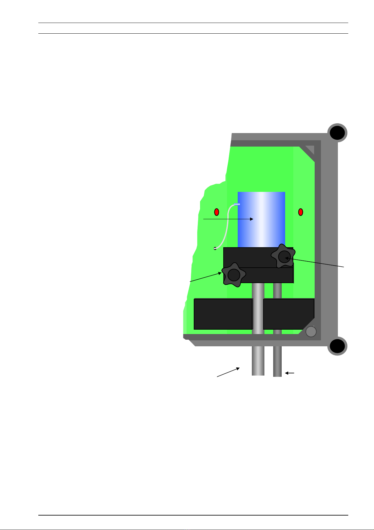
1. Open the front cover.
2. Pull the inlet tube out.
3. Loosen the screw at the bottle holders
upper part.
4. Release the bottle (pull it straight up).
5. If the bottle holderneeds to be cleaned,
loosen the screw at the bottle holders lower
part and pull the holder straight towards you.
6. Clean the bottle, tubes and holder with
washing detergents and water (when the
sampler is dirty, use diluted HCl).
7. Mount the parts in reversed order (point 5 - 1).
Be sure that the bottle is correct mounted.
8. Perform a manual sampling to check that the
parts are correctly mounted.

12
6.2 HARDWARE CHECK
A check of the hardware is only necessary if you suspect that there is something wrong with your water
sampler.
1 Disconnect the power supply.
2 Press Mand turn the power supply on, while keeping the button pressed during 10 seconds
(until the display shows CH01).
3 The sampler performs a self-test according to table 6.2.1.
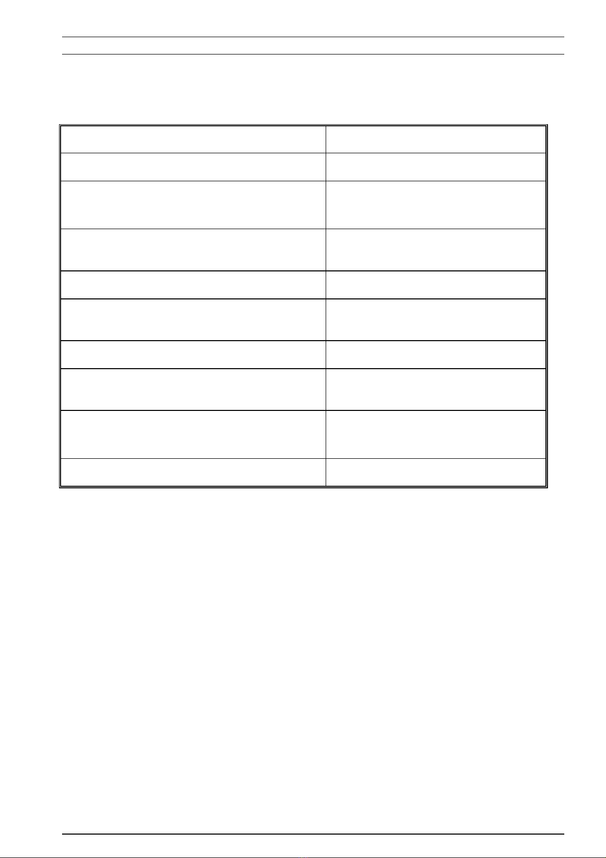
6.2.1 Hardware check
CH01 Test of the LED display All 4 LED-diodes lights up
CH02 Test of the function keys Press the keys in numeric order and the
corresponding sign is shown on the display
CH03 Test of valves & the compressor The display shows U1, U2, U3 when the
corresponding valve is tested and then conp when
the compressor is tested
CH04 Test of the IR-detectors E-01 shows on the display if the bottle is dirty, if
the bottle is clean the display shows Conn
CH05 Test of the overflow protection E-08 if there is water in the vacuum tube
NOVA if it is OK
CH06 Test of menu diodes All diodes on the menu line lights up
6.3 CALIBRATION
The water sampler is always pre-calibrated when delivered. Pre-calibration is only necessary when the sampler
has been shut of for a longer time.
6.3.1 Pre calibration
1. Disconnect the power supply.
2. Connect the reference instrument to VA/V3 through the Amphenol contact at the lower side of
VA/V3.
NOTE! Check the polarity; brown connector to +and blue connector to -.
3. Press -and turn the power supply on, while keeping the button pressed during 10 seconds until the
display shows Cal1.
4. Set the out signal from the reference instrument to 20.0 mA. Press =to continue.
5. The display shows C20.0 during 5 seconds.
6. The display shows Cal2. Set the out signal from the reference instrument to 4.0 mA. Press =to
continue.
7. The display shows C04.0 during 5 seconds.
8. The display shows Cal3. Set the out signal from the reference instrument to 0.0 mA. Press =to
continue.
9. The display shows C00.0 during 5 seconds.
10. The sampler returns to sampling mode.
11. The calibration is complete.
13
7. TROUBLESHOOTING
Press =to accept an error message The error still remains and should be corrected before sampling is starting
again.
CODE INDICATES CORRECTION
E-01 Dirty sample bottle Clean the sample bottle
E-02 No water in the tank Check the water level in the tank
Check tubes and connections
E-03 Sequence collision: to many
pulses
Reduce the number of pulses
E-04 The pulse length is to long> 5 s Check pulse transmitter
E-05 The pulse length is to short < 5
ms
Check pulse transmitter
E-06 Interval > max flow Decrease the interval
E-07 Max flow / interval > 36 samples
/ h
Increase the interval
E-08 Water in the vacuum tube
Overflow protection is activated
Contact Elmacron AB
E-99 Memory error Contact Elmacron AB

14
8. SPECIFICATIONS
Dimensions; casing 372 • 302 • 175 ( mm )
Sample volume Adjustable 20 - 50 - 100 - 150 - 200 - 250 ml / sample
Number of samples 1 - 36 samples / h
Main supply 220 V
Protection IP65
Max suction height 6 m
Alarm output Potential free contact, max load 24VDC
Control Internal time
External, potential free pulse
External, 0 / 4 - 20 mA
Pulse length Tonmax = 5000 ms, Tonmin = 5 ms. Toffmin = 50 ms Ton = Toff =
Consumption, Paverage 110 VA
Version
Table of contents
Popular Sampler manuals by other brands

PCE Health and Fitness
PCE Health and Fitness PCE-AS1 user manual

Sartorius
Sartorius MD8 Airport operating instructions

Korg
Korg M3 XPanded supplementary guide

Tisch Environmental
Tisch Environmental TE-5200 Operation manual

Spectrex
Spectrex PAS-500 operating manual

YZ Systems
YZ Systems DynaPak DP-2010FU Instructions & operating manual
