ELORA ELORA 3 User manual
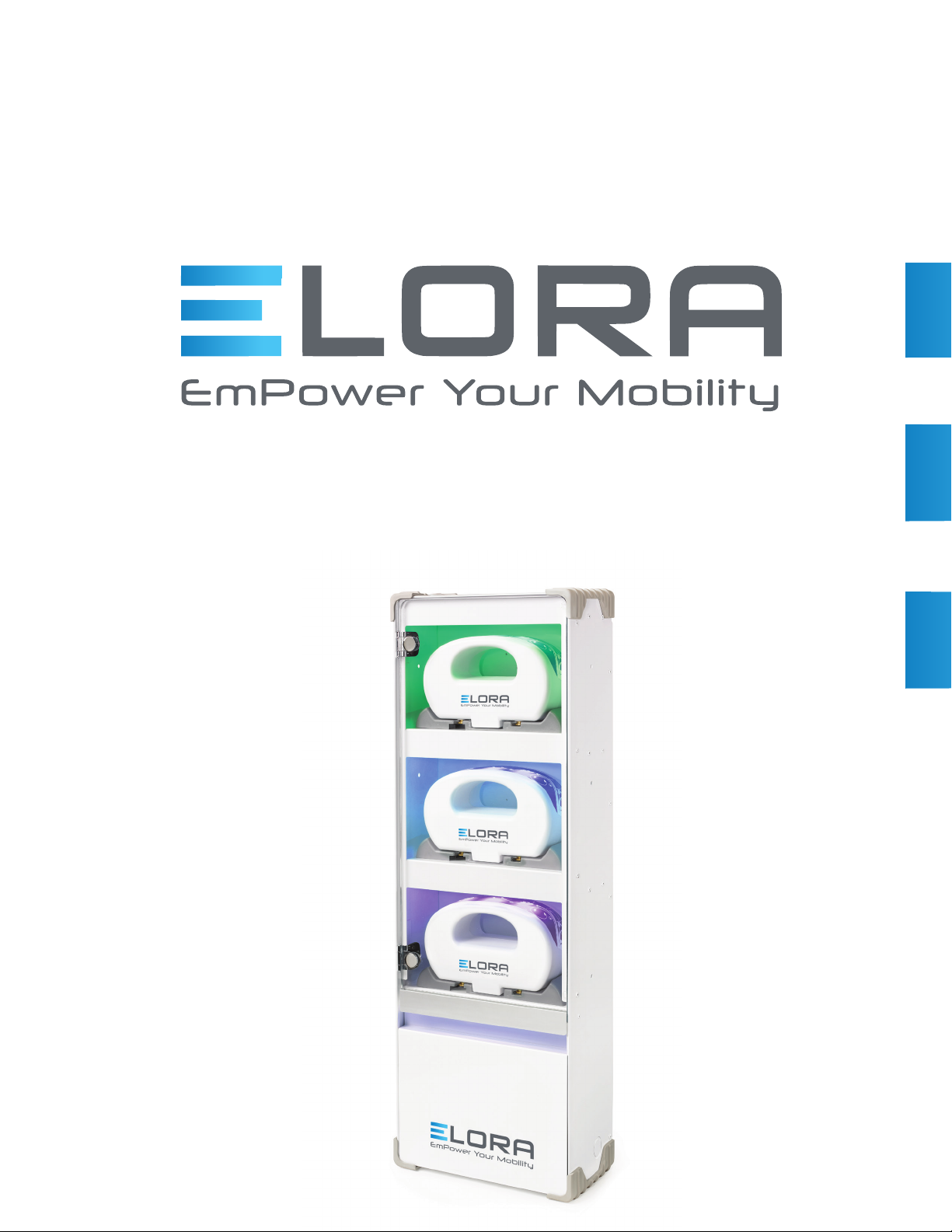
ELORA 3 STATION CHARGING CABINET
Owner’s Manual
7595-0445
Revision A

www.elorapower.com
ELORA 3 STATION CHARGING CABINET Owner’s Manual| 2
IMPORTANT
READAND UNDERSTAND THIS MANUAL BEFORE
OPERATION
INTRODUCTION
KEYFEATURES ANDBENEFITS
SPECIFICATIONS
WARNINGS-PRECAUTIONS
ORDERINGINFORMATION
3
4
4
6
13
14
CONTENTS

www.elorapower.com
ELORA 3 STATION CHARGING CABINET Owner’s Manual| 3
The ELORA™ 3Station Charging Cabinet is specically designed tobe operated
with current ELORA Series batteries. Do not attempt touse a non-ELORA Series
battery or batteries not manufactured by ELORA.
USE OF THIS CHARGER WITH ANY BATTERY NOT MANUFACTUREDBY
ELORA MAY RESULT IN BATTERY DAMAGE AND CAUSE RISK OF FIRE
OR PERSONAL INJURY. ELORA ACCEPTS NORESPONSIBILITY FOR
ANY INJURY OR DAMAGE ASSOCIATED WITH THE USE OF BATTERIES NOT
MANUFACTURED (OR BATTERIES SERVICED OTHER THAN) BY ELORA.SUCHUSE
WILL VOID ANY WARRANTY.
Special precautions and handling instructions are contained in this manual and should be strictly
adhered to for safe and reliableoperation. Contact ELORA Customer Support Group at
IMPORTANT
READ ANDUNDERSTANDTHIS
MANUAL BEFORE OPERATION!
Elora Customer Support
customers[email protected]
1-888-77ELORA

www.elorapower.com
ELORA 3 STATION CHARGING CABINET Owner’s Manual| 4
INTRODUCTION
KEY FEATURES & BENEFITS
STANDARD FEATURES
Simultaneous Charging for all ELORA batteries
300W Output
Full InterActive®technology (including I-Min),which
makes 3 simultaneous charge termination systems,
rejuvenation modes, and LifeSaver®maintenance mode.
UV LED to aid in disinfection control duringthe charging
process
LED “ready” Indicator Lighting
LED INDICATOR LIGHTS
TheEloraBattery Charging Cabinet contains a series of
LED indicators that inform the user of the current status of
each battery.
UV LED
When a battery is rst placed ontoa station and the door
is closed, theUV LED will begin the disinfection cycle to
aid in keepingthe battery germ and bacteria free. This is
indicated via the violet LEDs that will illuminate the charging
station. If thecabinet door is opened during disinfection
the cycle will be suspended while the door is open
and will recommenceonce the door has been closed.
Once thebatteryhas completed the disinfection cycle the
LEDs inside the cabinet will indicate the current state of
the battery.
BLUE LED
An illuminated blue LED indicates that the battery has
been completelycharged and is ready for use.
GREEN LED
An illuminated green LEDindicates that the battery has
been completelycharged, is readyfor use and has the
highest capacity (run-time). This is the battery that should
be removed rst. Only one battery will indicate green at
a given time. Once this battery has been removed the
next fully charged battery(if available) will illuminate green
indicatingthat it is ready for use and has the highest
capacity (run-time). This assures that not only willthe
battery with thehighest capacity be used but alsoensures
that only batteries that have been fully charged will be
put intoworkow, ensuring that the workow will not be
interrupted prematurely.
TheEloraBattery Charging Cabinet is a wall mountable charger capable of charging 3 batteries
in parallel. The cabinet can be mounted ush to the wall or recessed for a more aesthetic appeal.
Like all Elora chargers, everything is automatic. Once a battery is placed onto one of the
stations the charger will read thebattery’s current state of charge and will then automaticallygo
into one of theapplicable Three Stage Charging modes. At the same time the chargerwill begin
a disinfection sequence via its UV LEDs that will aid in keeping the battery germ and bacteria
free.
When theuser is prepared to remove a battery from the Elora Charging Cabinet, a green LED will
illuminatethebattery that should be used next. This feature ensures that all batteries throughout
the eet are used equallyto ensure maximum battery life.
www.elorapower.com
ELORA 3 STATION CHARGING CABINET Owner’s Manual| 5
KEY FEATURES & BENEFITS
SAFEGUARDS
Important: When powering with a generator, the gener--
ator MUST produce a sine wave or modied sine wave
output, otherwisethe charger may be damaged
personnel.
DISPOSAL
DO NOT dispose of the EloraChargingCabinet and its
associated components and/or accessories in municipal
waste at the end of their expected service life. Consult
Elora Customer Support Group for information on
disposal/recycling of the Elora Charging Cabinet and its
associated components and/or accessories.
OPERATING ENVIRONMENT
TEMPERATURE RANGE0ºC to 30ºC / 32ºF to 86ºF
RELATIVE HUMIDITY20-70% non-condensing
PRESSURE985 hPa – 1040hPa
TRANSPORTATION & STORAGEENVIRONMENT
TEMPERATURE RANGE-20ºC to 40ºC /-4ºF to 104ºF
RELATIVE HUMIDITY20-70% non-condensing
PRESSURE985 hPa – 1040 hPa
Deviceintended for Indoor Use Only.
Never useammable or combustible solvents around batteries or chargers.
Clean out dust and debris from charger vents and electricalcontacts by
blowing with compressed air.

www.elorapower.com
ELORA 3 STATION CHARGING CABINET Owner’s Manual| 6
SYSTEM SPECIFICATIONS
Power Supply Input Voltage = 120V/240V, 60/50Hz,
5A/2A
MAINTENANCE
Daily:
Ensure all connections between the device, associated
components, and accessories are snug and secure.
Weekly, or as needed:
Clean the device, associated components, and acces-
sories as needed with a damp, non-saturated cloth or
paper towel. Do not wet the exposed metal part of the
chargingunit. Do not use solvents or scouring agents.
Examples of approved solvents are Cidex®and Windex®
Consult Elora Customer Support Group for approved
list of cleaning agents. Contact Elora Customer Support
Group with additional inquiries as to maintenance.
GROUNDING / EARTHING
IMPORTANT WARNING: THIS APPARATUS MUSTBE
EARTHED
To ensure safe operation, the three pin plug supplied must
be inserted only intoa standard three-pin power point that
is effectively grounded through normal household wiring.
Extension cords used with the equipment must be three-
conductor and be correctly wired to provide connection
to earth ground. Improperly wired extension cords are a
dangerous electricalhazard.
Thefact that the equipment operates satisfactorily does
not imply that the power point is properly grounded and
that the installation is completely safe. If any doubt exists
about thecorrect grounding of the power point, consult a
qualied electrician.
SPECIFICATIONS
IMPORTANT: The wires in this main lead are colored in
accordance with the following code:
Green and yellow –earth
Blue –neutral
Brown – live
See installation instructions below for proper hard wiring
installation instructions.
CHARGE TIMES
The Elora Battery Charging Cabinet is fully compatible
with all current and future Elora series batteries
and delivers theadvancements and proven reliability
of InterActive charging.
Elora 240 Battery –4Hours Nominal
NOTE: If battery is completely discharged battery charging
may be delayed as the charger will enter the REJUVE
function, which brings thebattery up to acceptable levels
for charging.
REPAIR
The charger has no user serviceable parts. Please consult
Elora Customer Support Group for anyservice
questions.

www.elorapower.com
ELORA 3 STATION CHARGING CABINET Owner’s Manual| 7
SPECIFICATIONS
THREE STAGE CHARGING METHODOLOGY
In general, the EloraBattery Charging Cabinet will deliver
a Three Stage charge routine toeach battery.
1. Stage One will deliver a high rate charge matched to
the capabilities of the battery. During this stage, six sep-
arate cutoff methods are in operation, simultaneously,
ensuring the fastest, safest chargefor that battery:
CCO - This method requires theidentication of the
particular battery size (capacity) and chemistry, an
exclusive Elora feature. The charger determines
the maximum charge time for theparticular battery and
uses this information to ensure that overcharge condi-
tions are avoided.
STAGE ONE will deliver a charge matched to the capa-
bilities of the battery. During this stage, seven separate
cutoff methods are in operation, simultaneously, ensur-
ingthe fastest, safest charge for that battery:
TCO - Temperature cutoff which stops the Stage one
charge precisely when a temperature indicative of full
charge is reached;
Dt/dT - A microprocessor based algorithm which mea-
sures a rise in temperature over a specic time, very
accurately indicating full charge. This method is also the
recommended method for charging Ni-MH technology;
charging by identifying a characteristic “reverse slope”
of a Ni-Cd cell. Since this characteristic can be dis-
guised by the age, temperature and the number of the
cells in abattery, it can never be employed alone;
CCO - This method requires theidentication of the
particular battery size (capacity) and chemistry, an
exclusiveElora Logic Series ®feature. Thecharger
determines the maximumcharge time for the particular
battery and uses this information to ensure that over-
charge conditions are avoided.
FUL - This determination is made when a fullycharged
DIGITAL battery is returned to acharger within specied
parameters of time, temperature, and battery voltage.
The DIGITAL battery communicates its fully charged
condition and the charger conrms the parameters and
immediately indicates a fully charged condition, without
additional verication.
TEMPERATURE COMPENSATED VCO–For HyTRON™
series of batteries.Similar toa VCO, however, only
operates within certain temperature parameters;
I-Min – for Dionic®batteries, a seventh cutoff method
is employed. The battery is charged tospecic voltage
and I-Min current until fullcharge is reached. I-Min
is the “minimum current” ow required for proper cutoff
2. Stage Two charging is a “balancing” or “stabilizing”
mode which calculates each battery pack type to offset
any imbalanceof the battery’s cells, created by unequal
self-discharge or any capacity mismatch of the indi-
vidual cells in thepack. This stage can vary in duration
from zero to as much as 16 hours,depending on the
condition of the battery. The Stage Two charge for Elora
Series batteries reduces current automatically as the
battery charges maintaining the Lithium-ion cells at a
safe voltagelevel.
3. Stage Three charging is the Elora exclusive
Lifesaver
®maintenancemode. This patented pulse
routine keeps batteries fully charged, free from self-
discharge - indenitely – without damaging heat associ-
ated with a so-called “trickle charge”. The Stage Three
programming for Elora monitors the self-discharge of
the battery, providing charge only when the battery
self-discharges toabout 95% of its capacity.
4. NOTE: Batteries maybe kept on a charger until ready for
use. The Lifesaver mode will keep them 100% charged.
NOTE: Elora recommends that each battery have
a charge position, for when the battery is not in use.
A batterycan remain on an Elora charger indenitely.
www.elorapower.com
ELORA 3 STATION CHARGING CABINET Owner’s Manual| 8
SPECIFICATIONS
F/G Part numberDescription
84750123 Elora3 Station Charging Cabinet Wi-Fi ready
IEC60601-1
REMOVAL OFAC MAINS POWER
Elora recommends that batteries remain on the
chargerand plugged into AC mains for best results.
NOTE: Dueto thespecialized communications between
the charger and thebattery, only Elora Series
batteries should be used in this charging cabinet.
SHUTDOWN PROCEDURE
If theunit were to require shut down, the ON/OFF switch
to theunit is mounted on the front panel in the lower
right corner. The“O” indicates that the power is OFF. This
switch in theOFF position isolates the supply mains from
thedevice.The system may continue to run if batteries are
mounted whilethe device is isolated from supply mains.
If full shutdown is required then be sure to disconnect all
batteries as well.
ORDERING INFORMATION

www.elorapower.com
ELORA 3 STATION CHARGING CABINET Owner’s Manual| 9
SPECIFICATIONS
INSTALLATION INSTRUCTIONS
FOR ELORA 3STATION
CHARGING CABINET
SAFETY PRECAUTIONS
READ THESE INSTRUCTIONS BEFORE INSTALLATION.
THIS INSTALLATIONWILL REQUIRE AT LEAST 2
PEOPLE.
THE WALL MOUNTING BRACKETS MUST BE BOLTED
SOLIDLY TO THE WALL.
THE MOUNTINGBRACKETS MUST BE LEVEL AND
SPACED APPROPRIATELY BEFORE THE CABINETS
ARE INSTALLED.
ITEMS SHOULD NOT BE PLACED ON THE TOP OF THE
CABINETS.
USE CAUTION WHEN HANDLINGSHEET METAL PARTS,
THE EDGES MAY BE SHARP.
! CAUTION !
Make sure the wallmeets the load capacity requirements
for the cabinet being installed. The wall the unit is tobe
mounted to shall be ½” thick drywall or greater with studs
spaced 16” on center apart from each other. Refer to local
building codes for proper mounting requirements.
Elora Customer Support
customers[email protected]
1-888-77ELORA

www.elorapower.com
ELORA 3 STATION CHARGING CABINETOwner’s Manual | 10
SPECIFICATIONS
INSTALLATION INSTRUCTIONS
FOR WALL MOUNTED ELORA
CHARGING CABINETS
TOOLS NEEDED FOR INSTALLATION
Drill
1/8” Drill Bit
½” Drill Bit
Philips Head Screwdriver
Level
Square
REQUIRED COMPONENTS
Hardware to mount brackets tothe wall (Not Provided
by Elora)
A. Elora Charging Cabinet
B. Wall Mounting Bracket
C. #10 x 1¼ Self TappingPan Head Screws
D. (4) Toggler Snap toggle BA Heavy Duty 3/16” Toggle
Bolts
E. Recessed Mounting Bezel (for recessed applications
ONLY)
MOUNTING THE CABINET TO WALL
1. Remove the Elora Charging Cabinet from its packaging
2. Open the charging cabinet door and locate tothe (2)
6-32 x ¼ Pan Head Screws in the top chargingbay that
hold on themounting plate to the rear of the cabinet.
(see gure 1)
3. Remove these two screws (do NOT discard)
4. Push down on the mounting plate on the back of the
cabinet. This should allow it to be removed from the
cabinet.
5. Determine thevertical position at which the top of the
cabinet is tobelocated. This location should be aligned
with a stud within the wall. Failure to do socould result
in the cabinet becoming dislodged from the walland
could cause injuryand or damage to the unit.
6. Use themounting bracket as a template and mark the
locations on the line for the Bolts. Drillpilot holes using
a 1/8” drill bit.
7. Level and secure the mounting bracket to the wall using
(4) #10 x 1¼ Self Tapping Pan Head Screws through
the center holes on the mounting plate.
8. Reattach the cabinet tothe mounting plate usingthe
(2) 6-32 x ¼ Pan Head screws removed in step 2.
9. Plug in the cabinet usingthe 120V power cord supplied
with the unit.
10. Switch the on/off switch, located on thebottom of the
unit, to the on position.

www.elorapower.com
ELORA 3 STATION CHARGING CABINETOwner’s Manual | 11
SPECIFICATIONS
RECESSING THE CABINET WITHIN THE WALL
NOTE: In order to recess the cabinet into the wall you
must obtain themounting bezel (sold separately from
Elora, part number 80750236). This part is not
shipped as part of thestandard mounting hardware and
must be purchased separately.
1. Remove the Elora Battery Charging Cabinet from its
packaging.
2. Remove the rubber corner caps from the cabinet.
3. Locate theconduit knockout on bottom of the right
hand side of the cabinet and remove it.
4. Determine the vertical position at which the top of the
cabinet is to belocated. The Elora Battery Charging
Cabinet is designed to be installed between twostuds
(16” on center). This location should be aligned
between 2 studs within the wall. Failure to do so could
result in the cabinet becoming dislodged from the wall
and could cause injury and or damage to the unit.
5. The rough opening in the sheet rock should be approx.
31-1/8”tall and 12-1/8” wide. This will allow for the
cabinet tot inside of the opening and for the mounting
bezeltoattach tothe wall without any open spaces
around the cabinet to be visible. Use caution when
removing sheetrockto ensure that no existing wiring or
plumbing within thewall is disturbed.
6. After creating the rough opening use the mounting
bezelas a templateand mark the locations for the
bolts.
7. Drill pilot holes usinga1/2” drill bit.
8. Adhering tolocal electric code connect the wiringto
the cabinet.
9. Test the power to thecabinet byswitching the on/off
switch totheon position. The green LED lights in each
bay should light up. Then turn power back off to
complete installation.
10. Attach the mounting bezel to the cabinet using the
(10) 10-32 x 3/8 Pan Head screws.
11. Level and secure the Charging Cabinet and Bezel to
the wall using 4 Toggler Snap toggle BA heavy Duty
3/16” Toggle Bolts toalign with the 4 corner holes on
the mountingbezel.
12. Switch the on/off switch, located on thebottom of the
unit, to the on position.
! CAUTION !
Recessing the cabinet within the wall requires a licensed
electrician. Please consult local electric code for require-
ments on installing this device within the wall.
www.elorapower.com
ELORA 3 STATION CHARGING CABINETOwner’s Manual | 12
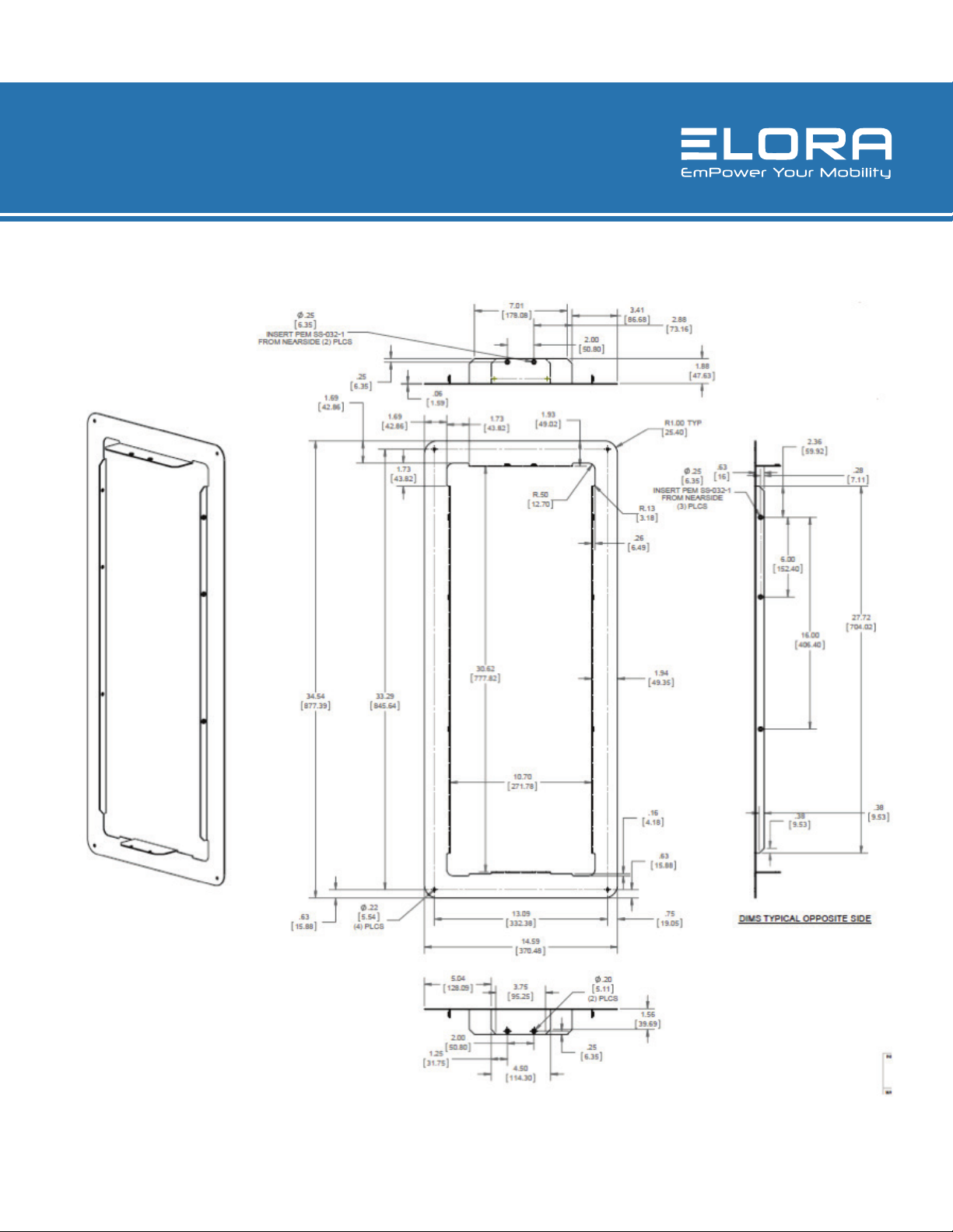
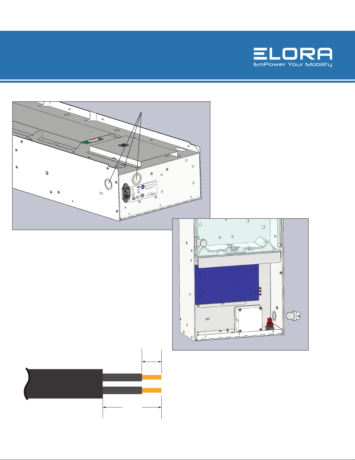
LINE DRAWINGS
SPECIFICATIONS
www.elorapower.com
ELORA 3 STATION CHARGING CABINETOwner’s Manual | 13
SPECIFICATIONS
2”
1/2”
Direct Wire
-Remove applicable knockout
Assemble a ULlisted conduit con-
nector inthe opening
A. Removable Retaining Nut
B. StrainRelief
Feed the exible conduit through the strain relief,
allowing enoughslack to easily attach wiring to the
device.
Tightenstrain relief screw against the exible conduit.
Knockout
www.elorapower.com
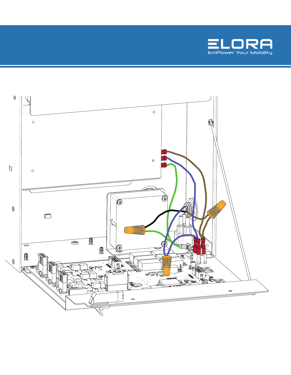
ELORA 3 STATION CHARGING CABINETOwner’s Manual | 14
SPECIFICATIONS
Complete wiring as shownbelow.
www.elorapower.com
ELORA 3 STATION CHARGING CABINETOwner’s Manual | 15
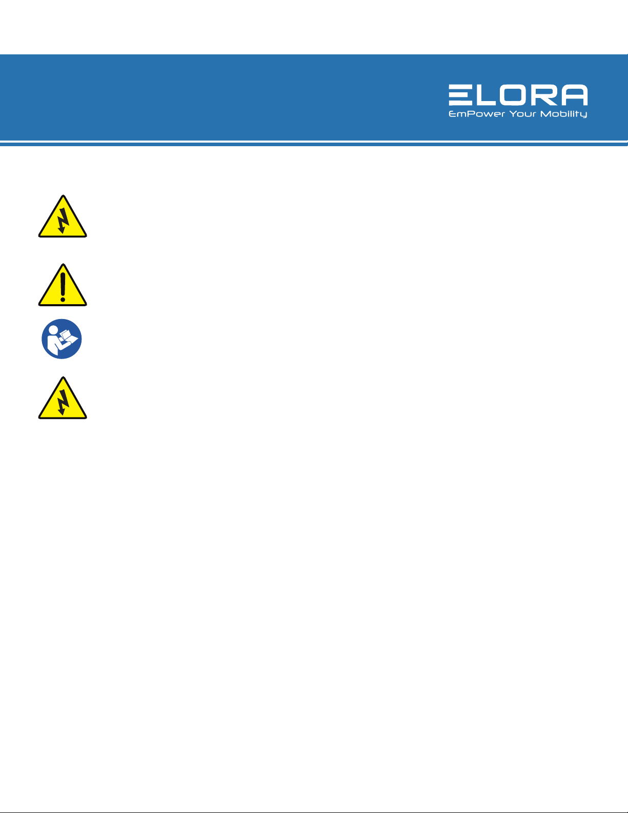
WARNINGS/PRECAUTIONS
WARNING!
Indicates possibilityof physicalharm to the
user incaseof non-compliance
CAUTION!
Indicates possibilityof damage to the
equipment incase of non-compliance
FOLLOW OPERATING
INSTRUCTIONS
WARNINGS!
1. DO NOT OPEN TO REDUCE THE RISK OF
FIRE OR ELECTRICSHOCK. THERE ARE
NO SERVICEABLE PARTS INSIDE – REFER
TO QUALIFIED SERVICE PERSONNEL
2. It is recommended that you return the interface to a
qualied dealer for any service or repair, incorrect as-
sembly may result in electric shock or re.
3. To reducerisk of electric shock, unplugthe DC input
(battery) before attempting any maintenance or cleaning.
4. To reducerisk of damage to electric plug and cord, pull
by plug rather than cord when disconnectinganything
from theunit.
5. An extension cord should not be used unless absolutely
necessary. If an extension cord is used, make sure that
is has a 3-prong, male plug (NEMA1-15P and 3-Prong),
female receptacle (NEMA1-15R).The size of the current
carrying conductors should be such that they are able
to carry at least 2.5A for the length of the extension.
6. Place the unit in an area that will allow air to ow freely
around theunit. DO NOT block or obstruct vent open-
ings or install theunit in an enclosed compartment.
7. Keep theunit away from moisture and water
8. Never operate two or more units in parallel.
9. Not approved for use in the patient environment.
10. Never attempt to charge any battery that is damaged
in any way.
11. WARNING:To avoid risk of electric shock, this equip-
ment must only be connected to a supply mains with
protective earth.
12. WARNING:Nomodication of this equipment is
allowed.
13. Do not manually depress and/or override the cabinet
door’s interlock switch.
14. WARNING: This deviceis designed to conform to
Electromagnetic Compatibility (EMC) standard IEC
60601-1-2 and will operate accurately in conjunction
with other medicalequipment which alsomeets this
requirement. To avoid interference problems affecting
the device, do not use the devicein the presence
of equipment which does not conform tothese
specications.
FCC NOTICE
This equipment has been tested and found to comply with
the limits for a Class A digital device pursuant to Part 15
of the FCCRules. These limits are designed toprovide
reasonable protection against harmful interference when
the equipment is operated in acommercial environment.
This equipment generates, uses, and can radiate radio fre -
quency and, if not installed and used in accordance with
the instruction manual, may cause harmful interference
to radio communications. Operation of this equipment in
a residential area is likely to cause harmful interference
in which casethe user will be required to correct the
interference at their own expense. This equipment has
been approved by one ormore agencies. All changes and/
or modications not expressly approved by Elora
International. could void the users’ warrantyand authority
to operatethis equipment. There are no serviceable parts in
this equipment.

www.elorapower.com
ELORA 3 STATION CHARGING CABINETOwner’s Manual | 16
WARRANTY
This warranty for the product specied in this document (“Product”)
is given by Elora Power. If you (the purchaser of the Product
from Elora, or the person for whom the Product was purchased, if it
was a gift) have any questions regarding Product applications,
Product specication, or to obtain warranty service on this or any
Elora product, contact the company at the address above.
THIS PRODUCT MUST BE REGISTERED WITH ELORA
WITHIN 30 DAYS OF PURCHASE TO ASSURE WARRANTY
COVERAGE.
REGISTER ONLINE AT www.elorapower.com
Warranty registration, including the serial numbers of Elora
chargers used with this battery, must be supplied to Elora.
Elora will warranty the Product only against defects in material and
workmanship for the period as follows from the date of
purchase, in accordance with the terms set forth below, and then,
only if the Product is used exclusively in conjunction with compati-
ble Elora chargers. If this charger is returned to Elora for warranty
service it will be required that you provide model names and serial
numbers of compatible Elora chargers with which this product was
used.
ELORA3 STATIONCHARGE
24 months: Elora will repair or replace the Product at Elora’s option
and cost.
This warranty shall be effective only if Elora receives notice
of such defects in materials or workmanship during the period of
the warranty.
The liability of Elora hereunder is expressly limited to a claim
for repair or replacement of the Product or as otherwise stated
herein at Elora’s sole discretion. Notice of any claim under this
warranty shall be delivered to Elora during the period of the
warranty and the Product shall be returned with its packaging
promptly, at your expense, to an Elora Customer Support Center or
to the address above. Upon receipt of the Product and a record of
your compliance with the conditions of this warranty, Elora will
repair or replace the Product and return it to you, or issue a credit,
as applicable. You are responsible for all shipping and handling
charges to and from authorized facility. THIS WARRANTY DOES
NOT APPLY TO AND IS VOID IN THE CASE OF DEFECTS OR
DAMAGE RESULTING FROM ACCIDENTS, DISASTER, NEGLECT,
MISUSE, IMPROPER INSTALLATION, IMPROPER OR UNAUTHORIZED
SERVICE OR MAINTENANCE, UNAUTHORIZED REPLACEMENT PARTS
OR ATTACHMENTS; OR DYSFUNCTION OR MALFUNCTION OF, OR
CAUSED BY, ANY OTHER PRODUCT OR DEVICE. Misuse includes any
use of the Product in other than its intended application, including the
use of this Product with any charging device or accessory not manufac-
tured by and/or specied by Elora International. This warranty does not
cover, and Elora assumes no responsibility for, any equipment or
devices used in conjunction with the Product.
ELORA INTERNATIONAL DISCLAIMS ANY LIABILITY FOR INCIDENTAL
OR CONSEQUENTIAL DAMAGES FOR BREACH OF ANY WRITTEN OR
IMPLIED WARRANTY OF THE PRODUCT. UNDER NO
CIRCUMSTANCES WILL ELORA INTERNATIONAL BE RESPONSIBLE
FOR ANY SPECIAL, INCIDENTAL OR CONSEQUENTIAL DAMAGES.
This Warranty is to be construed and enforced in accordance with
the law of the State of Ohio, including the provisions of the Uniform
Commercial Code as adopted and from time to time amended in the
State of Ohio, and not the Convention for the International Sale of
Goods. This choice of Ohio law is exclusive of any Ohio law that would
require reliance on any law foreign to Ohio. Should any action of law or
in equity be brought by any person under this Warranty, such action shall
be brought only in the United States District Court for the District
of Ohio, or in any Superior Court in Delaware County, Ohio, USA. Some
states do not allow limitations on how long a warranty lasts, so the time
period limitation herein may not apply to you. Some states do not allow
the exclusion or limitation of incidental or consequential damages, so the
above limitation or exclusion may not apply to you. This warranty gives
you specic legal rights and you may have other legal rights which may
vary from state to state.
Use of unauthorized equipment in conjunction with Elora
products constitutes misuse under our warranties and may limit or
void those warranties. Elora does not authorize, condone,
recommend, or otherwise assume any liability or responsibility
resulting from the use of any battery, charger, or accessory made by
Elora with any battery, charger or accessory not manufactured,
produced or sold by Elora. Elora only authorizes
the use of original Elora products with this Product. Use only
original Elora equipment with this Product.

Elora Customer Support
customers[email protected]
1-888-77ELORA
Call1-888-77ELORA or emailus at customers[email protected]
Visit our website at
www.elorapower.com
Copyright 2019 Elora International. All rights reserved.
Table of contents
Other ELORA Batteries Charger manuals


