Elpas ALC Outdoor LF BUS Beacon User manual
www.elpas.com
Page 1 of 12
V11/March 2015
ALC Outdoor LF BUS Beacon
For P/Ns: 5-ALC01122-0, 5-ALC01123-0 (with Loop)
Installation Guide
Introduction
This installation guide provides basic instructions for common ALC Outdoor LF BUS Beacon with Loop installation scenarios.
CAUTION! It is important that you read and follow the instructions in this document. If you have questions, call your local Elpas support representative.
Reasonable effort was made to ensure that the specifications and other information in this guide are accurate and complete at the time of its publication. Nonetheless,
all information contained in this document is subject to change at any time without prior notice.
Any modifications to this equipment without prior written consent of Elpas Solutions Ltd. will void all warranties including the pertinent regulatory certifications and as
such revoke your authority to operate this product. Furthermore unauthorized modifications may also result in damage to this device and may cause a safety hazard to
the users.
Product Description
The Elpas ALC LF BUS Beacon is a fully supervised, 125KHz emitter
that adds instantaneous location, choke-point (e.g. gate or door),
awareness to security, and safety applications. The sealed beacon
enclosure enables installation outdoors where long range LF coverage is
often needed.
The ALC LF BUS Beacon generates a user-adjustable, elliptically shaped
field up to 4m/13ft (perpendicular to the device) and 3.5m/11.5ft (parallel
to the device) in radius that can be used to cover a single interior
doorway. Optionally, up to three ALC LF BUS Beacons can be deployed
in ‘Primary–Secondary’ (up to two secondary devices) topologies to
cover large double-doors or architectural complex indoor entrance/exit
areas. The DIP Switch setting determines which is primary and which is
secondary.
The ALC LF BUS Beacon with external loop antenna generates a user-
adjustable, cylindrically shaped field of 2.2m high (nominal range) along
the loop cable (for a 3-conductor cable loop of 1.4mm wire diameter
(1.5mm2), buried 5cm under concrete or asphalt pavement). The device
supports loop cables 10-80m long.
The ALC LF BUS Beacon contains two general purpose analog inputs
(IN1 and IN2) and two open collector outputs (OC1 and OC2). The
device forces a choice between IN2 and OC2. The device also provides
the choice of either two digital inputs or two 26-bit Wiegand device
outputs. The DIP Switches setting determines these selections.
Note: Installation should be done only by a professional.
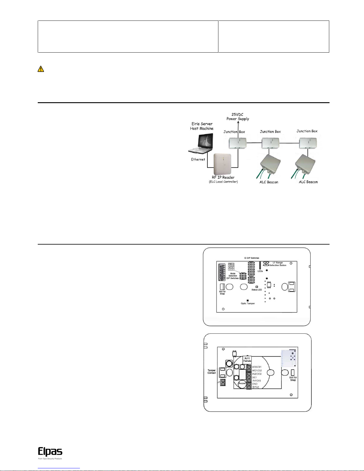
ALC with Loop Beacon - Sample Network Topology
Note: An Elpas RS-485 BUS may contain up to fifteen Elpas BUS devices (such as RF or
IR Readers, Elpas Display Panels, LF Beacons or other Primary BUS Beacons) which are
wired together with Elpas RS-485 Junction Boxes (P/N:5-JBA10485).
ALC LF BUS Beacons – Front View
Front Cover Tamper Contact: ALC BUS Beacons contain an optical tamper which
indicates non-authorized attempts to remove the device front cover tray when in
operation.
Status LED: All BUS beacons contain a Red, Green and Amber LED array that
detail the status of the devices:
Green LED
oUnregistered: Flashes once/second
Red LED
oInvalid ID: Flashes once/second - See page 4 for additional details
oDevice Back Tamper: Flashes once/second
oOutput Activated: Flashes once
oSynch Cable Disconnect (in secondary): Flashes continuously.
Orange LED
oContinuous indicates normal state
oFlashes to indicate the front cover is not properly closed
Note:
oLEDs are visible only when front cover is removed.
oLED colors may also be controlled remotely as ELC Actions or Eiris
Outputs.
ALC LF BUS Beacons – Rear View
RS-485 Interface: ALC BUS beacons contain a female RJ-11 connector to link to
the RS-485 Junction Box. This connector transfers both power & data. (See page 2
for details)
Buzzer: The beacon has a buzzer that sounds when an improper ID Address is
assigned. (See page 4 for details.)
General Purpose Inputs: ALC BUS Beacons include one set and one selectable
general purpose inputs. (See page 6 for details.). The beacons also provide the
choice of either two digital outputs or one 26-bit Wiegand device output. (See page
6 for details.)
Output (User Selectable): The beacons provide either two digital outputs or one
26-bit Wiegand device output. (See page 6 for details.). The beacons also include
one set and one selectable open-collector outputs.
Important: An electric current runs through the LF coil. The current is especially
strong at the vias. Do not touch.
ALC LF BUS Beacon PCB (Front View)
ALC LF BUS Beacon PCB (Rear View)
IMPORTANT: BUS Beacons MUST BE powered-down while you wire the
unit’s I/Os and when you connect to the RS-485 BUS. This prevents
accidental damage to the devices caused by shorts/spikes.
ALC Outdoor LF BUS Beacon with Loop – Installation Guide
www.elpas.com
Page 2 of 12
V11/March 2015
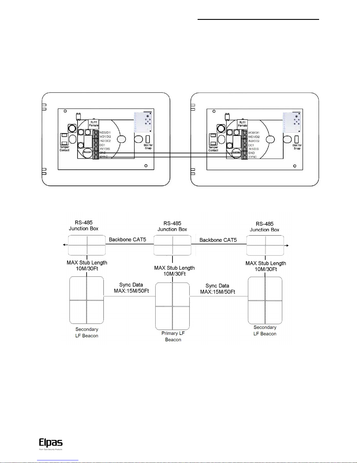
Primary/Secondary Synchronization (for 5-ALC01122-0 only)
Up to three LF BUS Beacons can be deployed in ‘Primary–Secondary’ topology to cover large double-doors or architectural complex indoor
entrance/exit areas.
Note: When you connect two secondary LF BUS Beacons, you must install them on either side of the primary LF BUS Beacon. For example,
install one to the right of the primary, and install the second to the left of the primary.
When deploying this topology, the LF fields generated by the secondary beacons MUST BE synchronized to pulse at precisely the same
moment in time as the LF field generated by the primary unit in order to avoid mutual interference between any of the LF fields.
To implement Primary/Secondary Synchronization, users must physically connect a Sync Data Link (typically using a 2x2x26 Category 5 cable)
between the GND and SYNC terminals of the Primary Beacon and all of the Secondary devices.
Primary Secondary
Primary/Secondary Synch Data Connection Diagram
Note: It is not necessary to connect each beacon to a different Junction Box as in the diagram. One Junction Box can power two or three as
well.

ALC LF BUS Beacon – Installation Guide
www.elpas.com
Page 3 of 12
V11/March 2015
Supervision Messages (RF version only)
ALC transmits supervision messages which alert ELC (Elpas Local Controller) in case the ALC antenna or synch cable is disconnected, the
tamper is triggered or restored, ALC is lost or online, or if the voltage is low. ALC Outdoor LF BUS Beacon with Loop provides two options for
supervision messages transmission, RF and BUS. When RF is in use, ALC does not require connection to additional devices. ALC transmits
supervision messages to ELC through RF. In BUS, ALC is wired to ELC through RS-485 BUS which transmits the supervision messages.
ID Address Setup
Before initial power-up, the Primary ALC LF BUS Beacon must be assigned a unique ID Address (Neuron ID) in order for the Eiris Software
Platform or an Elpas Local Controller to be able to identify the device. Convert the Neuron ID (typically using a scientific calculator) into the
two-digit hexadecimal number that correctly corresponds to the DIP switch found on the LF Beacon. This hexadecimal number is used to
register the beacon ID address into the Eiris or the ELC database.
Note: It is vital that a newly assigned ID Address does not conflict with any other ID Address that is already assigned to any other beacon.
These Neuron ID Addresses SHOULD NOT BE ASSIGNED to the Primary ALC LF BUS Beacon: 0x00 (00000000), 0x13 (00010011),
0x35 (00110101), 0x4B (01001011), 0x4D (01001101), 0x5C (01011100), 0xB8 (10111000), 0xD5 (11010101), 0xDC (11011100), 0xFF (11111111),
0xFE (11111110) and 0x7F (01111111).
If any of the above ID addresses is assigned by mistake, the beacon does not function properly. Additionally, the beacon Red Status LED flashes
continually; and the device buzzer is sound repetitively.
Secondary ALCs IDs:
When connected to ELC, ALCs set as secondary do not require an ID. If an ID is set, Eiris ignores it.
When used as standalone, transmitting to Eiris, use the extra four DIP switches to set a secondary identifying number for secondary ALCs. Make sure the
extra four DIP switches in the primary ALCs are set to 0. Otherwise, Eiris events recognize them as secondary ALCs.
Use the beacon 8-poisition DIP Switch (added 4, only for secondary ALCs) to set the ID address (in binary format) of the beacon as illustrated
below.
The ID address is assigned using a binary coded hexadecimal number.
Switches 1-4 (high nibble) are used to set the first hexadecimal digit while
switches 5-8 (low nibble) are used to set the second hexadecimal digit.
Together, the two hexadecimal digits provide a total of 256 possible
Neuron ID addresses.
The figure below shows how to set the hex digitals ‘0’ to ‘F’
Below are three examples of addresses set in hexadecimal:
ALC Outdoor LF BUS Beacon – Installation Guide
www.elpas.com
Page 4 of 12
V11/March 2015
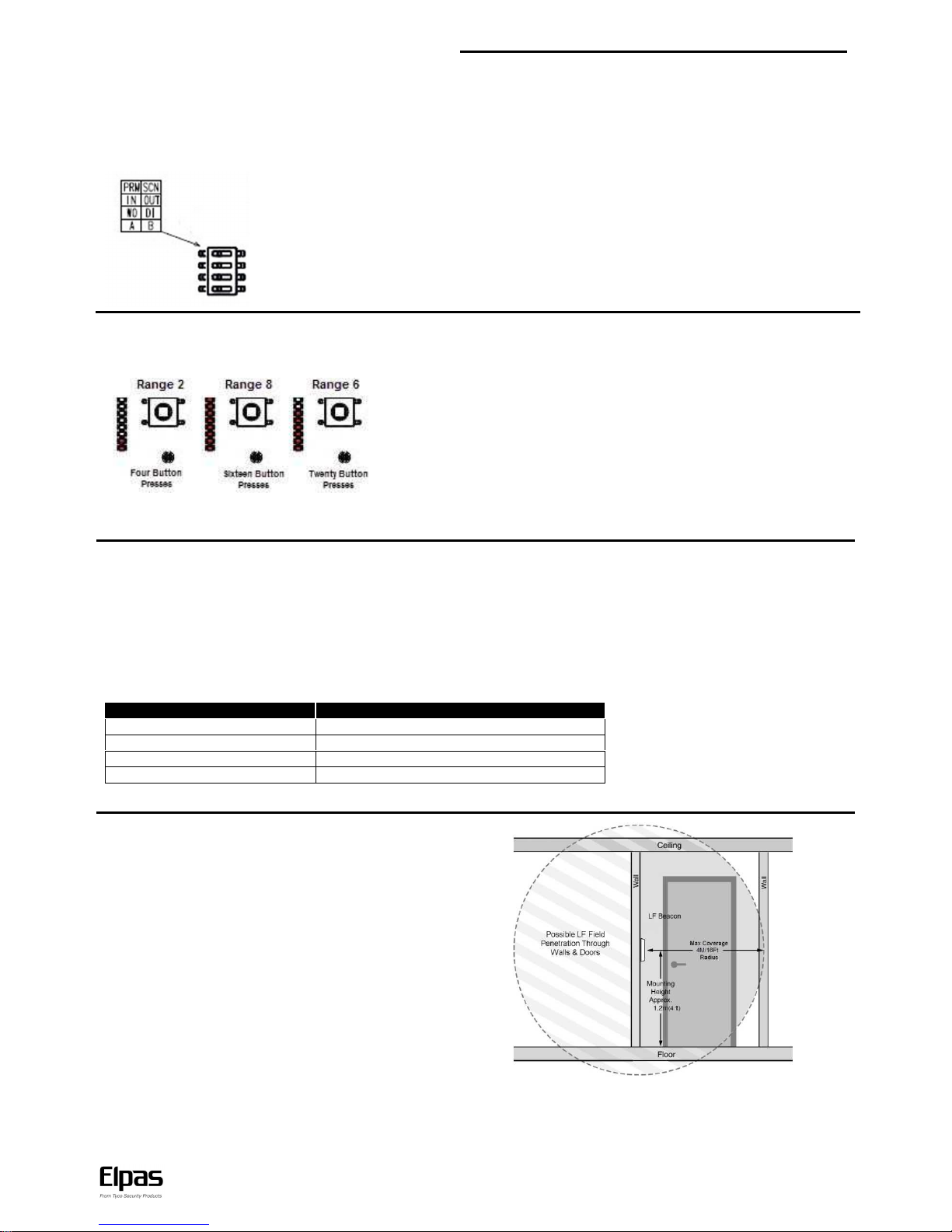
Mode Selection
Mode selection DIP switches on the front of the PCB allow users to select whether a certain device is a primary or a secondary one, whether the
device uses Wiegand outputs or digital outputs, and whether the device uses a second input or a second open-collector output.
To set according to your requirements, see the table next to the set DIP switches:
Top Switch – Push left to set device as Primary. Push right to set device as Secondary.
Second Switch – Push left to set a second Input. Push right to set a second open-collector output.
Third Switch – Push left to set Wiegand outputs. Push right to set digital inputs.
Bottom Switch – In a secondary beacon, set to A for an in-phase magnetic field or B for an out of
phase magnetic field, according to configuration with primary.
LF Field Adjustment
The size of the LF field generated by any of the BUS Beacons can be adjusted using the button to control the actual coverage of the LF field and
to reduce the unwanted signal penetration.
ALC LF BUS Beacons support eight ranges. The LED indicators on the front of the
PCB (next to the DIP Switches) show the range. To set the range, press the button
next to the LED indicators. Each double button press sets to a higher range. After you
get to the eighth, every double button press sets to a lower range. From 1 to 8 and
from 8 to 1.
Note: You must open the front cover to access the button and see the LEDs.
Note: In practice the coverage area (for each range mode) regardless of beacon type may vary +/- 20% by specific Active RFID Tag as well as
the active RFID Tag’s physical orientation in relation to the LF field.
Key Mounting Considerations
1. LF BUS Beacons MUST NOT BE MOUNTED directly onto any metallic surfaces.
2. LF BUS Beacons MUST NOT BE MOUNTED closer than 30cm/12in from metal barriers (such as signs/pillars/beams) in any direction.
3. LF BUS Beacons MUST BE MOUNTED as far away as possible from all other pieces of equipment (such as large electrical motors, HVAC
and refrigeration compressors) that may emit magnetic fields.
CAUTION! To ensure the safety of all individuals who need to be in the general area of the beacon’s LF field for extended periods of time the
installer MUST ENSURE that the beacon is installed at a location such that personnel remain at a sufficient distance as advised by the guidelines
below:
Distance
Time
0-30 cm (0 -12 inches)
Up to 30 minutes per day
30-60 cm (12 -24 inches)
Up to 180 minutes per day
60-90 cm (24-35 inches)
Up to 9 hours per day
Plus 90 cm (more than 35 inches)
No time limit
Note: Distances do not account for an external loop.
Single Device Placement (without loop)
Mount the beacon on the wall, at a height of 1.2m/4Ft. above the
ground (as with indoor).

ALC Outdoor LF BUS Beacon – Installation Guide
www.elpas.com
Page 5 of 12
V11/March 2015
Door Primary – Secondary Placement (without loop)
A primary/secondary configuration may be installed by mounting the primary and secondary beacons on opposite sides of the door, at
a height of 1.2m/4Ft above the floor.The resulting LF fields are automatically synchronized in real time to avoid problems associated
with coverage area overlap.
Corridor Primary – Secondary Placement (without loop)
A primary/secondary configuration may be installed by mounting the primary and secondary beacons on opposite sides of the
corridor, at a height of 1.2m/4Ft above the floor.The result is a uniform LF field between them that provides full coverage.
Note: In the primary beacon, there is no need to set the bottom Mode Selection DIP switch.
Note: For a primary with two secondary beacons configuration, contact Elpas Support.
ALC Outdoor LF BUS Beacon – Installation Guide
www.elpas.com
Page 6 of 12
V11/March 2015
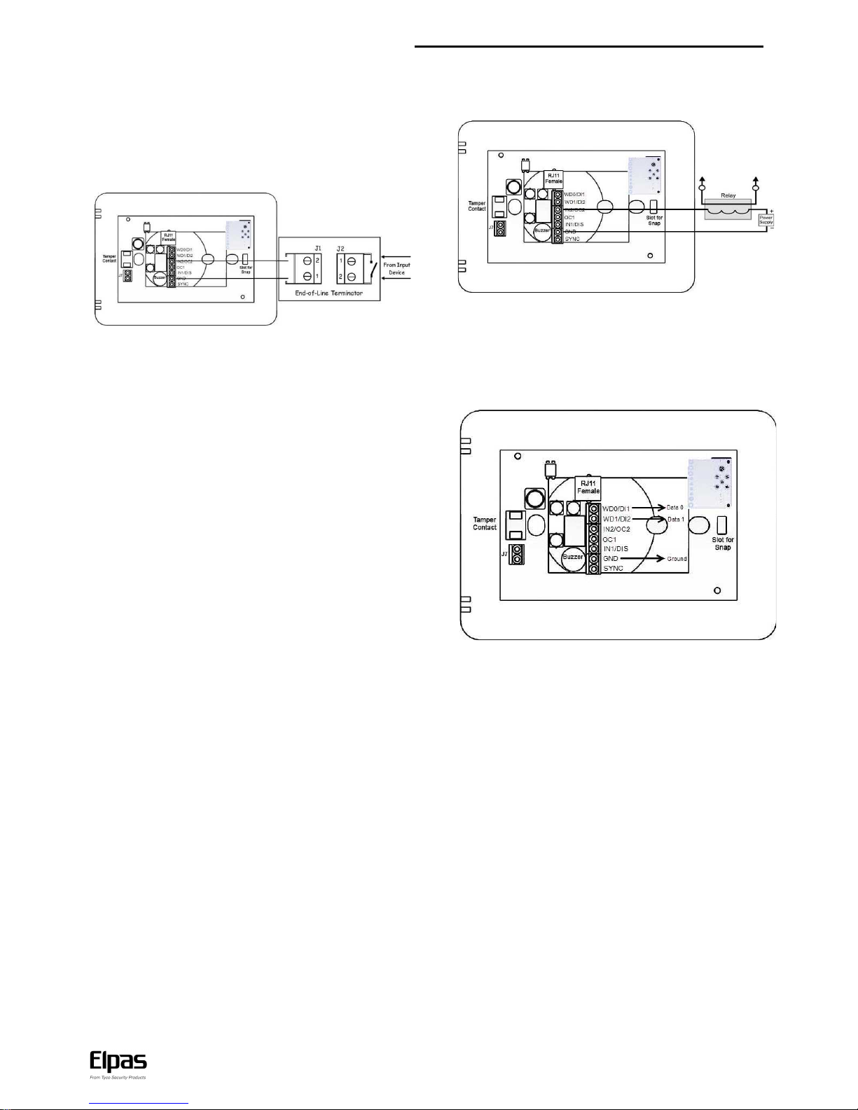
General Purpose Inputs
The beacons have two digital inputs (can be selected as Wiegand
outputs). The beacons also include two general purpose dry
contact analog inputs (N.O.) for monitoring alert sensors or
emergency call buttons. They are designated as IN1 and IN2 (can
be set as open-collector- output2).
EOL supervision may be added to either of these inputs to detect:
Open, Close, Line Cut, and Line Short circuit conditions using
optional Elpas End-of-Line Terminators (P/N: 5-IOX00001).
Recommended Cable: 22 AWG, unshielded/twisted pair.
Transmission Suppression Option
Input1 on all BUS Beacons may be used to disable the LF field by
shorting IN1 with GND. This allows the user to temporarily
override the beacon with a security detector, such as a door
position reed switch, which can disable the LF field as long as the
door is shut.
However IN1 can be used as a normal general purpose input
when an Elpas End-of-Line Terminator, (P/N: 5-IOX00001) is
connected to the input as illustrated in the above section.
Open-Collector Output
Both the primary beacon and the secondary beacon have two
open-collector outputs (up to 100mA, 28VDC) for actuating alert
response devices.
Note: The output is resistive loading only, there is no power factor.
Recommended Cable: 22 AWG, unshielded/twisted pair
Wiegand Output
ALC beacons provide a 26-bit Wiegand output, consisting of two
ports WD0 and WD1 (it may be enabled instead of the digital
inputs using the DIP switch) for sending Elpas tag IDs to third-
party access control panels.
Recommended Cable: 22 AWG, unshielded/twisted pair
ALC LF BUS Beacon – Installation Guide
www.elpas.com
Page 7 of 12
V11/March 2015
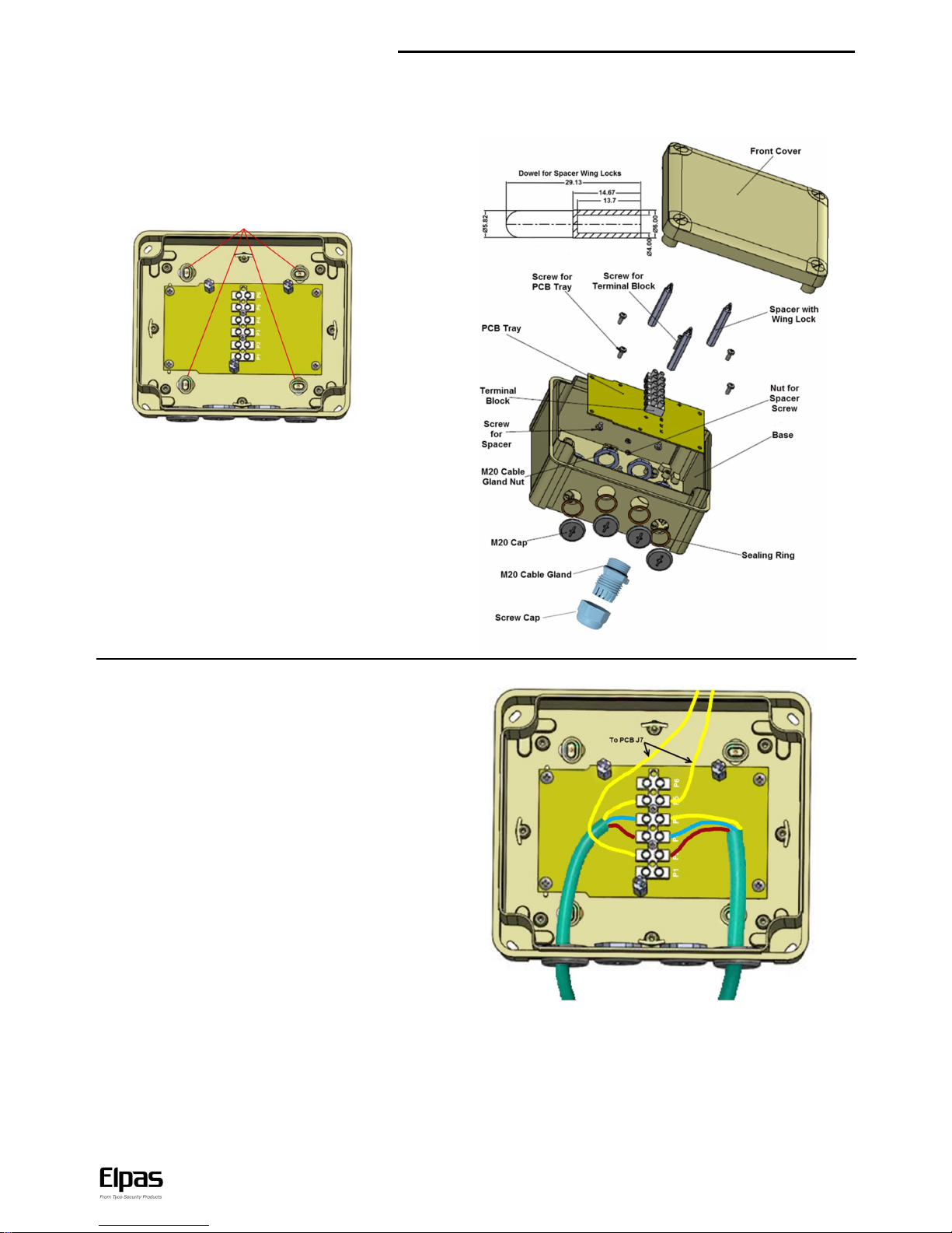
Mounting
The ALC Outdoor LF BUS Beacon with Loop enclosure is comprised of a base, PCB tray with spacers, and a cover. The enclosure comes with
cable gland to seal the cables to the enclosure.
1. To open the enclosure, use a flat head screwdriver to remove
the screws in the corners and open.
2. To remove the PCB, tuck in the spacer wing locks with either a
finger nail or a hexagon socket and lift PCB.
3. Drill holes to match mounting screws, and insert screws to
mount.
4. Use attached black plastic caps to seal mounting holes.
5. Insert and connect the loop (if using) and if required, synch and
BUS cables (see Connecting the Loop).
6. Place PCB back into place (fit spacers through the respective
holes), and push down until the spacer wing lock fasten the
PCB. Make sure to place PCB so the terminals face inward.
Note: To remove PCB, use attached, 6mm dowel to tuck in the
spacer wing lock, and pull up PCB.
7. Place front cover back into place and fasten the cover screws.
Connecting the Loop
1. Loosen two Cable gland nut and remove caps.
2. Insert each end of the loop through the screw cap, cable gland,
and through the cable hole.
3. Release the terminals to which you want to connect the loop
conductors, and connect the conductors.
Make sure each conductor is connected by an offset of one
terminal. For example: If you connect one end of the red
conductor to terminal P2, connected the other end to terminal P1.
Connect the other conductors in the same fashion, and that the
order within the conductors is identical on each side.
4. Make sure the cable gland is positioned, and tighten the cable
gland nut.
5. Tighten the screw cap to the cable gland to seal the cable to the
gland.
6. To connect the loop to the ALC PCB, connect two cables to the
free sides of the terminals to which the loop is connected on only
one side. On the PCB end, connect the cables to terminal block
J7 (order in the J7 terminal is not important).
Note: Insert a BUS or I/O cable (or any other cable) with the glands
and screw caps in the same manner as the loop cable, and connect to
the appropriate PCB terminals.
Note: When you open the enclosure to connect/replace/remove a
cable, you trigger the tamper and the Tamper alert.

ALC Outdoor LF BUS Beacon – Installation Guide
www.elpas.com
Page 8 of 12
V11/March 2015
Extended Properties in ALC Eiris Object
The ALC Extended Properties tab allows users to see how the optional settings of the device are set. The Extended
Properties tab also allows users to select readers to be associated with ALC.
LF Id (Hex) field: Displays the hexadecimal representation of the set LF ID.
Dip Switch field: Displays the binary representation of the set LF ID. 1 represents a DIP switch set as ON, o represents a DIP switch set
as off.
Wiegand check-box: Selected when the top two input terminal are set as Wiegand.
Wiegand Facility Code field: Enter the Facility Code programmed into the Wiegand device.
Transmission Range field: Displays the set LF range level.
Wiegand Bit Length drop-down list: Select the Wiegand bit length.
Select readers that will be associated to LF: Select to enable reader selection. The readers list opens and allows you to select readers
to be associated with the ALC represented by this object.
CPLD version field: Displays the current CPLD firmware file.
RF version field: Displays the current RF firmware file.
Note: When you update the firmware in the General tab, notice there are two bin files. One for the CPLD, and one for the RF. The file
name indicates for which component it is. Update both files.
Primary/Secondary field: Displays whether the ALC is set as Primary or Secondary.
IN2/OC2 field: Displays whether the ALC third terminal is set as input 2 or O.C. output 2.
Wiegand out/Digital inputs field: displays whether the top two terminal blocks are set as two digital inputs or as one Wiegand output.
Door/Hallway field: Displays whether the ALC is set to be in Primary-Secondary door or hallway configuration (on the PCB, marked as A
or B, respectively).
Note: Select ALC Secondary LFs is not relevant for ALC with Loop (5-ALC011230) that does not require secondary ALCs.
ALC LF BUS Beacon – Installation Guide
www.elpas.com
Page 9 of 12
V11/March 2015
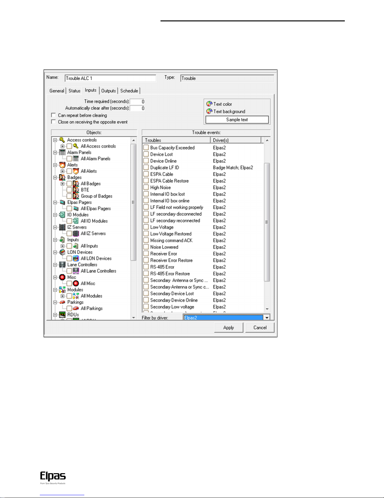
ALC Trouble Alert in Eiris – Inputs Tab
The Eiris alert type relevant for ALC devices is the Elpas2 Trouble alert.
To select relevant device events, in the Filter by driver drop-down list, select Elpas 2.
Note: LF Secondary events are relevant only in Standalone configuration. In Standalone configuration, secondary ALCs have no Eiris objects.
The Primary to which they are connected reports events related to them.
Note: For further details about alerts, see the Eiris Configuration Guide, section 5.
ALC Outdoor LF BUS Beacon – Installation Guide
www.elpas.com
Page 10 of 12
V11/March 2015
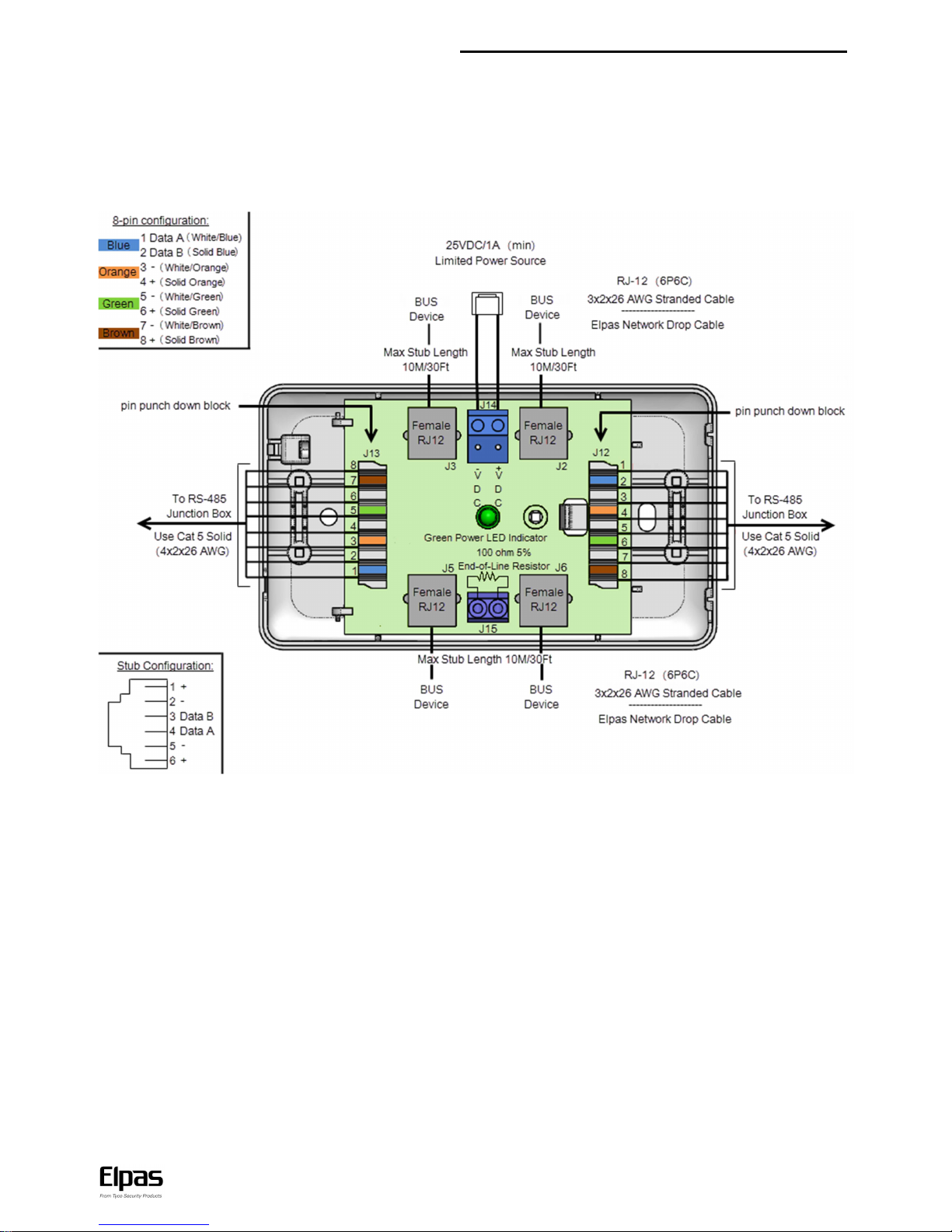
RS-485 BUS/Stub Topology
The RS-485 BUS MUST Be wired using a BUS/Stub topology where the BUS Master (an RF IP Reader or an ELC Controller) is connected anywhere along the BUS.
The topology supports data transmission between the BUS Master and up to 15 Elpas BUS Devices (such as RF or IR Readers; LF Beacons, Remote Display Panels
I/O Boxes and Proximity Readers) using multiple Elpas RS-485 Junction Boxes (P/N: 5-JBA10485).
IMPORTANT NOTE: Only 1 RF IP Reader/ELC Controller and up to 7 RF BUS Readers may coexist together on a single BUS.
200M/650Ft: Max. BUS length 10M/30Ft: Max. Stub length 100 Ohm Termination: Required each end of the BUS.
Recommended Cable/Power Supply Types:
BUS Backbone:
CAT5 solid (4x2x26AWG).
Power: Three twisted pairs
(six conductors) between junction boxes.
Data: One twisted pair (two conductors) between junction boxes.
Power: 25 VDC/1A Limited.

ALC LF BUS Beacon – Installation Guide
www.elpas.com
Page 11 of 12
V11/March 2015
Product Specifications
Technology
Low frequency (LF) cylindrically shaped field (125 KHz)
Radio frequency (RF) (433 MHz)
LF Transmission Rate
Continuous bursts of LF transmissions (each about 12ms in duration)
RF Transmission Rate
Supervision messages of every 60secs
Supervision Event Messages
3 RF transmissions (each transmission
@4ms in duration), 312.5ms apart
Output and Format
3-byte messages (preamble, beacon ID and CRC)
Electrical
Message Length
4-31 byte messages (encapsulated for messages > 4 bytes)
RS-485 BUS
230Kbit/sec
Device Supervision
Lost Away, Low Voltage, Communication Problems, Enclosure Tamper
Buzzer
Tamper: 1 second beep
Software/Controller driven
Range Indicator LEDs
The number of lit LEDs indicate the LF field range
Orange LED
Device connected and registered in Eiris or ELC: Continuous
When front cover is not properly closed: Flashes.
Can be driven remotely
Green LED
Firmware download: Flashes
When front cover is not properly closed: Flashes more frequently
Can be driven remotely
RED LED
Invalid ID Code: Flashes
Unregistered in Eiris Software: Flashes
Power up/Communication Loss: Flashes
Sync Cable Disconnect (in Secondary):Flashes
When back cover is not properly closed: Flashes
Can be driven remotely
ID Code
Set by an onboard, 8 -position DIP switch
Input/Outputs
Two N.O. dry contact analog inputs, one optional: Transmission suppression through input and the other optional output
Two optional digital inputs (rated 100mA/12VDC)…..Two optional Outputs: One 26-bit Wiegand device
Two dry contact open-collector outputs, one fixed and the other optional
Input Supervision
4 Levels (Open, Closed, Line Short, Line Cut) using optional Elpas End-of-Line Terminator
Power Requirements
12–28Vdc, 55mA @ 24VDC, 500mA max Approved limited power supply
Cable Loop Antenna Range
The device supports cable lengths of 10-80m with an LF range (nominal) of 2.2m above ground when a 3-conductor,
1.4mm diameter (1.5mm2) cable is buried 5cm under concrete or asphalt pavement.
Recommended Cable for Loop
Use the following or an equivalent: Standard - IEC 60502; No. X nominal area of the conductors - 3x1.5No.*sqmm; Min.
no. of wires in phase conductor - 1; Nominal insulation thickness - 0.7mm; Nominal outer sheath thickness - 1.8mm:
Overall approx. diameter - 10mm: Cable weight approx. - 150kg/km; DC resistance @ 20°C - 12.1/km; Ampacity @ 30°C
– 24A (Air), 31A (Earth); Gain: -8.2dBi
General
Construction
Polycarbonate plastic, white (IP 67)
Dimensions (H x W x D)
1890 X 1600 X 820mm (74.5 X 63 X 32.3in)
Weight
530grams (18.7oz)
Tamper Protection
Optical Tamper. Projects light. When the cover does not return the light, the tamper is triggered.
Device Interfaces
RS-485 Bus & Power: One Female RJ-11 (6P6C) connector
Supervised Input: Two–Position terminal block…….Digital Output: Two–Position terminal block
Primary/Secondary Output Field Synch: Two–Position terminal block
Optional 26 bit Wiegand Outputs: Two–Position terminal block
Operating Environment
Temp: -30 – 70C (-22 – 158F);Humidity: 95% Non-condensing
Management Software
Eiris 4.9.1 (or higher) Software
Regulatory
CE, FCC, IC compliant
Warranty
1 year limited
Ordering Information
Part Number
Description
5-ALC01123-0
ALC LF BUS Beacon with Loop
5-ALC01122-0
ALC Outdoor LF BUS Beacon
5-IOX00001
End-of-Line Terminator for Elpas & AXS Inputs (5 units)
5-JBA10485
RS-485 Junction Box, 4 RJ11 Ports
5-LFM00125
LF Field Meter
Accessories
Part Number
Description
5-ERS02721-1
Network Drop Cable, 5.0 Meters/16.0 Feet
5-ERS02800
P60 Power Supply, 24VDC/2.2A
K-207133
Wires kit

ALC Outdoor LF BUS Beacon – Installation Guide
Page 12 of 12
V11/March 2015
W.E.E.E. Product Recycling Declaration
For information regarding the recycling of this product you must contact the company from which you orignially purchased it.
If you are discarding this product and not returning it for repair then you must ensure thatit is returned as identified by your supplier.
This product is not to be thrown away with everyday waste - Directive 2002/96/ECWaste Electrical and Electronic Equipment.
Compliance with Standards
This device complies with FCC Rules Part 15 and with Industry Canada license exempt
RSS standard(s). Operation is subject to two conditions:
(1) This device may not cause harmful interference
(2) This device must accept any interference that may be received or that may cause
undesired operation.
Le présent appareil est conforme aux CNR d'Industrie Canada applicables aux appareils
radio exempts de licence. L'exploitation est autoriséeaux deux conditions suivantes :
(1) l'appareil ne doit pas produire de brouillage, et
(2) l'utilisateur de l'appareil doit accepter tout brouillage radioélectrique subi, même si
le brouillage est susceptible d'en compromettre le fonctionnement.
NOTE: This equipment has been tested and found to comply with the limits for a Class
B digital device, pursuant to Part 15 of the FCC Rules. These limits are designed to
provide reasonable protection against harmful interference in a residential installation.
This equipment generates uses and can radiate radio frequency energy and, if not
installed and used in accordance with the instructions, may cause harmful interference
to radio communications. However, there is no guarantee that interference will not
occur in a particular installation. If this equipment does cause harmful int erference to
radio or television reception, which can be determined by turning the equipment off and
on, the user is encouraged to try to correct the interference by one or more of the
following measures:
Reorient or relocate the receiving antenna.
Increase the separation between the equipment and receiver.
Connect the equipment into an outlet on a circuit different from that to which the receiver is connected.
Consult the dealer or an experienced radio/TV technician for help.
Cet équipement a été testé et jugé conforme aux limites s’appliquant à un
appareil numérique de classe B, conformément à la Partie 15 des
réglementations de la FCC. Ces limites ont été élaborées pour offrir une
protection raisonnable contre les interferences nuisibles dans une installation
résidentille.
Cet équipement génère, utilize et peut émettre de l’énergie de fréquence radio et,
s’il n’est pas installé et utilize conformément aux instructions du fabricant, peut
provoquer des interférences dangereuses pour les communications radio. Toutefois,
rien ne garantit l’absence d’interférences dans une installation particulié re. Si cet
équipement provoque des interférences nuisibles au niveau de la réception radio ou
television, ce qui peut étre determine par la mise hors, puis sous tension de
l’équipment, vous étes invite à essayer de corriger les interferences en pregnant les
mesures suivantes:
Réorientez ou déplaces l’antenne réceptrice.
Augmentez la distance qui sépare l’équipement et le récepteur.
Branchez l’équipement à une prise d’un circuit different de celui auquel est
branché le récepteur.
Consultez le revendeur ou un technician radio/television expérimenté pour
obtenir de l’aide.
Warning!
Changes or modifications to this equipment not expressly approved by the party
responsible for compliance (Elpas Solutions Ltd.) could void the user’s authority
to operate the equipment.
Europe
This equipment complies with the RTTE requirements - Directive 1999/5/EC of
the European Parliament and of the council of 9 March 1999.
EN 300220, EN 301489, EN 50130-4, EN 61000-6-3, EN 60950-1.
Product Warranty
Elpas Solutions, Ltd. (Elpas or the Company), and its affiliates, warrants its products (hereinafter referred to as "the Prod uct”) to be free of defects in materials and workmanship
under normal operating conditions and use for a period of one year from the date of shipment by Elpas. The Company’s obligations shall be limited within the warranty period, at its
option, to repair or to replace the defective Product or any defectiv e component or part thereof. To exercise this warranty, the product must be returned to the manufacturer freight
prepaid and insured.
This warranty does not apply to repairs or replacement caused by improper installation, Product misuse, failure to follow ins tallation or operating instructions, alteration, abuse,
accident, tampering, repair by anyone other than Elpas, external causes, and failure to perform required preventive maintenan ce. This warranty also does not apply to any products,
accessories, or attachments used in conjunction with the Product, including batteries, which shall be covered solely by their own warranties, if any. Elpa s shall not be liable for any
damage or loss whatsoever, whether directly, indirectly, incidentally, consequentially or otherwise, resulting from a malfunction of the Product due to products, accessories, or
attachments of others, including batteries, used in conjunction with the Product.
ELPAS MAKES NO EXPRESS W ARRANTIES EXCEPT THOSE STATED IN THIS STATEMENT. ELPAS DISCLAIMS ALL OTHE R WARRANTIES, EXPRESS OR IMPLIED, INCLUDING
WITHOUT LIMITATION IMPLIED WARRANTIES OF MERCHANTABILITY AND FITNESS FOR A PARTICULAR PURPOSE. ELPAS’S SOLE RESPONSIBILITY FO R WARRANTY CLAIMS
IS LIMITED TO REPAIR OR TO REPLACE AS SET FORTH IN THIS STATEMENT.
Elpas shall have no liability for any death, personal injury, property damage, or other loss whether direct, indirect, incident al, consequential, or otherwise, based on a claim that the
Product failed to function. Howev er, if Elpas is held liable, whether di rectly or indirectly, for any loss or damage arising under this limited warranty or otherwise, regardless of cause
or origin, the company's maximum liability shall be limited to the purchase price of the Product, which shall be fixed as liq uidated damages and not as a penalty, and shall be the
complete and exclusive liability of Elpas.
Elpas shall not, under any circum stances whatsoever, be liable for any inaccuracy, error of judgment, default, or negligence of Elpas, its employees, officers, agents, or any other
party, or of the purchaser or user, arising from any assistance or communication of any kind regarding the configuration, design, installation, or creation of security system involving
the Product, that being the responsibility of the purchaser or u ser. If Elpas is unable to make such repair or replacement, the company’s entire liability shall be limited to the cost of
a reasonable substitute product. Elpas shall not be responsible for any dismantling, installation, reinstallation, purchasing , shipping, insurance, or any similar charges.
Elpas shall have no liability for any damages, including without limitation, any direct, indirect, incidental, special, or co nsequential damages, expenses, costs, profits, lost savings
or earnings, or other damages arising out of the use of the Product or the remov al, installation, reinstallation, repair or replacement of the Product or any related ev ents. In the
ev ent that there is any liability against Elpas, such liability shall be limited to the purchase price of t he Product which amount shall be fixed as liquidated damages.
The purchaser and user understand that this Product may be compromised or circumvented by intentional acts; that the Product will not in all cases prevent death, personal injury,
property damage, or other loss resulting from burglary, robbery, fire or other causes; and that the Product will not in all cases provide ad equate warning or protection. The
purchaser and user also understand that a properly installed and maintained alarm may reduce the risk of events such as burglary, robbery, and fire without warning, but it is not
insurance or a guarantee that such events will not occur or that there will be no death, personal injury, property damage, or other loss as a result of such events.
By purchasing the Product, the purchaser and user shall defend, indemnify and hold Elpas, its officers, directors, affiliates, subsidi aries, agents, servants, employees, and
authorized representatives harmless from and against any and all claims, suits, costs, dama ges, and judgments incurred, claimed, or sustained whether for death, personal injury,
property damage, or otherwise, because of or in any way related to the configuration, design, installation, or creation of a security system involving the Product, and the use, sale,
distribution, and installation of the Product, including payment of any and all attorney’s fees, costs, and expenses incurred as a result of any such events.
The purchaser or user should follow the Product installation and operation instructions and test the Product and the entire system at least once each week. For various reasons,
including but not limited to changes in environmental conditions, electric, electronic, or electromagnetic disruptions, and t ampering, the Product may not perform as expected. The
purchaser and user are advised to take all necessary precautions for the protection and safety of persons and property.
This statement provides certain legal rights. Other rights may vary by state or country. Under certain circumstances, s ome states or countries may not allow exclusion or limitation
of incidental or consequential damages or implied warranties, so the above exclusions may not apply under those circumstances and in those states or countries.
Elpas reserves the right to modify this statement at any time, in its sole discretion without notice to any purchaser or user. However, this statement shall not be modified or varied
except by Elpas in writing, and Elpas does not authorize any single individual to act on its behalf to modi fy or vary this statement. Any questions
about this statement should be directed to Elpas.
This manual suits for next models
2
Table of contents


