Teradek BOLT 4K 750 RX User manual

Reference Guide
© 2020 Teradek, LLC. All rights reserved.
v1
Bolt 4K
750/1500/ MAX


TABLE OF CONTENTS
Physical Properties ........................................ 2
Getting Started ............................................. 4
Device Operation .................................... 4
Power and Connect ................................. 4
Power Connector/Pin-Out ........................ 5
Custom 3rd Party Cables.......................... 5
12G-SDI Input/Output Cables................... 5
Pairing .................................................... 5
Bolt App.................................................. 6
Mounting...................................................... 8
Vertical and Horizontal Antennas .............. 8
Recommended Antenna Orientation .......... 8
Array Panel Antenna ................................ 9
Device Placement .................................. 10
Transmitter Display Operation...................... 11
Receiver Display/OSD Operation................... 15
Bolt Manager .............................................. 21
Troubleshooting/FAQ .................................. 23
Frequencies by Region ................................. 25
Technical Specifications .............................. 26
Support Resources ...................................... 29
Disclaimer .................................................. 29
Warning ..................................................... 29
FCC Statement .......................................... 29
EC Declaration of Conformity ...................... 29
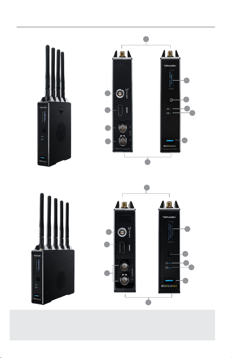
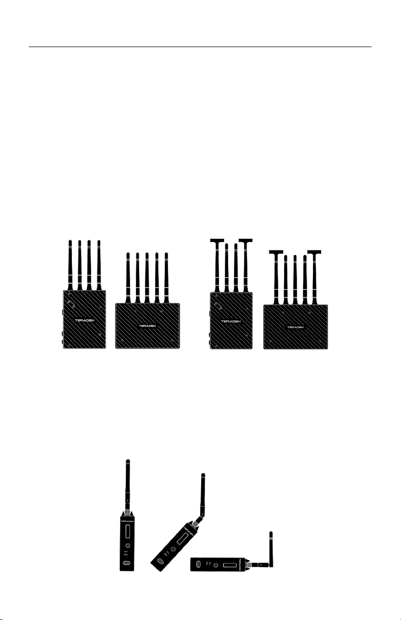
PHYSICAL PROPERTIES
A: RP-SMA connectors
B: 6-28V DC power input
C:HDMI input
D:12G-SDI output
E: 12G-SDI input
F: OLED display
G:Menu joystick
H:Network status
I: Video status
J: Power switch
K:Mini-USB (not shown)
L: HDMI output
BOLT K TRANSMITTER
C
B
A
J
F
G
H
I
D
E
L
BOLT K RECEIVER
2
K
A
J
F
G
H
I
K
B
D
Teradek, LLC 2020. All rights reserved. v1.3-0620
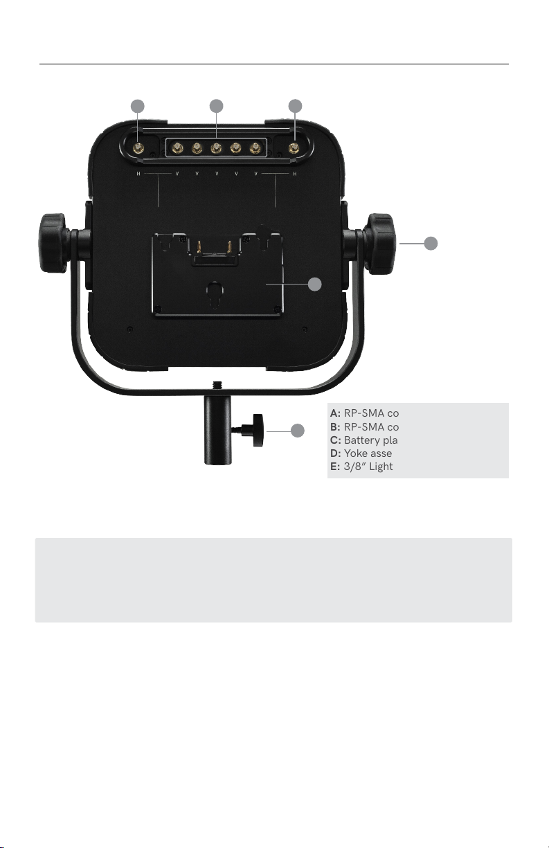
BOLT 4K ARRAY PANEL ANTENNA
A: RP-SMA connectors (vertical)
B: RP-SMA connectors (horizontal)
C: Battery plate
D: Yoke assembly
E: 3/8” Light stand adapter
C
B
BA
D
3
E
ANTENNA CONFIGURATION
The Array Panel Antenna has both vertical (A) and horizontal (B) antenna connectors. The
transmitter's antenna configuration will determine which Array Panel RP-SMA connectors you
use with the receiver. For more information, go to Vertical and Horizontal Antennas on page 8.
GETTING STARTED
POWER AND CONNECT
Connect the output from your video source to either the SDI or HDMI input (C or E)
on the Bolt transmitter. Connect either the SDI or HDMI output (D or L) from the Bolt
receiver to the video input on your monitor.
Attach the antennas to both the transmitter and the receiver. If using an Array
Antenna with the receiver, mount the receiver to the back of the antenna, then
connect the five RP-SMA connectors to the center connectors labeled Vusing the
included extension cables. If the transmitter is using horizontal antennas, attach
the receiver’s two outward connectors to the antenna’s two external connectors
labeled H (see page 8).
Connect power to the Bolt transmitter and receiver with the included A/C adapter,
or if both devices are equipped with battery plate accessories, attach a compatible
battery (Gold or V mount).
Move the power switches on both the transmitter and receiver (J) to the ON position.
Video appears within a few seconds.
1
3
2
4
NOTE: If mounting the receiver upright on a stand above the monitor, use a right-
angle SDI adapter to relieve any strain caused by the weight of the cable, and to
avoid damaging the SDI output’s internal connectors.
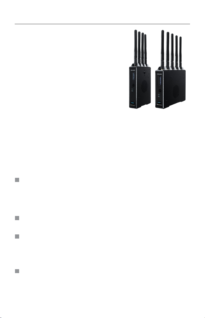
Bolt 4K is the first visually lossless, zero delay
4K wireless video transmission system. Bolt 4K
transmits 10-bit, 4:2:2 HDR video at a range of up
to 750/1500 feet line-of-sight over the unlicensed
5GHz band, and can multicast to six receivers
simultaneously.
For HDR workflows, Bolt 4K supports the HDR-10,
PQ, and HLG standards and can transport extended
camera metadata, timecode, and record triggers
over the wireless link.
• Keep the transmitter and receiver at close range for 60 seconds after powering
on the devices. This allows them to scan for and select the best wireless frequency.
DEVICE OPERATION
• For best results when using multiple Bolt systems in the same area, place the
transmitters and receivers a few feet apart from each other.
• Operation of other wireless equipment may interfere with the Bolt. Try to separate
other wireless transmitters and receivers as much as possible.
4

Teradek, LLC 2020. All rights reserved. v1.3-0620
POWER CONNECTOR/PIN OUT
Bolt devices purchased as a set (TX and RX), are paired by default, requiring no
additional configuration. Bolt devices purchased separately need to be paired using
the device's front panel (OLED) menu, Bolt Manager, or the Bolt App.
PAIRING
NOTE: Before starting either pairing process, ensure that both the transmitter and
receiver have the same firmware version and have Bluetooth enabled.
Select Pairing to begin the pairing process. The transmitter will begin scanning for
a receiver within range and automatically pair to the receiver.
Using the Menu Joystick (G), navigate to the Pairing menu on both the transmitter
and the receiver.
2
1
PAIRING VIA THE FRONT PANEL MENU
Once paired, the front panel will indicate whether or not Pairing is successful.
3
Using a reverse polarity or improperly−constructed power cable can
damage the product and is not covered under warranty.
* Pin 1 is closest to the red dot on the connector
Pin Description
1* GND
2 +DC
Bolt devices use a locking 2-pin power connector similar to the 0B 302 series
LEMO connector.
• Test the power cable polarity with ONLY the power cable connected to Bolt. Do
not connect video cables.
• Check the power cable for shorts and proper grounding.
CUSTOM/RD PARTY POWER CABLES
5
G-SDI CABLES
Bolt 4K devices require the use of 12G-SDI cables in order to reliably transport 12G
video signals, and are included as a standard item. Ensure that your cables are rated
for compatibility with your camera's output.
CAUTION:

Select the transmitter you wish to pair, then tap the Next button.
Open the Bolt App from your iOS or Android device, then tap the Pairing button.
2
1
PAIRING VIA THE BOLT APP
Select the receiver(s) you wish to pair with the transmitter, then tap the Pair! button.
The Bolt App will indicate when the pairing process is completed.
3
Open Bolt Manager, select the Pairing tab, then tap the Wired Pairing button.
Connect both the transmitter and receiver(s) to your computer (Windows/Mac) via USB.
2
1
WIRED PAIRING VIA BOLT MANAGER
Select the devices you want to pair, then click the Pair Devices button. Bolt
Manager will indicate whether or not Pairing is successful.
3
PAIRING TIPS
If you’re having trouble getting units to pair, we recommend keeping the transmitter and receiver six feet
apart when pairing (if antennas are connected). Without antennas, they can be closer. Keep all other
RF devices nearby turned o or out of range to ensure the transmitter and receiver are only detecting
each other. To eliminate any chance of interference, perform the Wired Pairing process via Bolt Manager.
BOLT APP
2
1
3Navigate to the Bluetooth menu on both the
transmitter and receiver, then select Enable.
Download the Bolt App.
Open the Bolt App from your iOS or Android
device, then tap the Bolt Devices button.
Use the Bolt App to remotely manage and monitor every parameter of Bolt 4K
including pairing, frequency selection, and 3D LUTs.
Select the device(s) you want to pair or monitor.
4
CONNECT VIA BLUETOOTH
Enable Bluetooth on your iOS or Android device.
5
6
Teradek, LLC 2020. All rights reserved. v1.3-0620
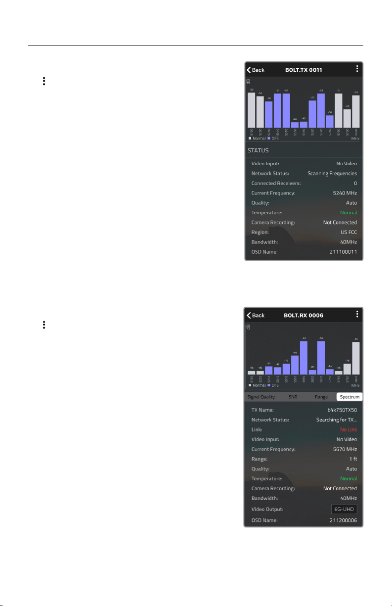
TRANSMITTER STATUS DISPLAY
Spectrum Analyzer - Detects congestion in the
area and determines which frequencies are
available to use. Each bar represents a frequency,
and the height represents the amount of congestion
in that frequency.
Status - Displays the current status of your input,
including frequency and frequency information,
camera recording status, temperature, and
amount of linked receivers.
Settings (Menu descriptions listed on pg. 11) - Tap
the button at the top of the screen to customize the
transmitter’s various settings.
RECEIVER STATUS DISPLAY
SNR (Signal to Noise Ratio) - Compare the signal
power level to the noise power level from the
attached antennas.
Range Analyzer - Displays the transmission distance
between the transmitter and receiver.
Settings (Menu descriptions listed on pg. 11) - Tap
the button at the top of the display to customize
the receiver’s various settings such as the output
format, audio, display and OSD.
Spectrum Analyzer - Detects congestion in the
area and determines which frequencies are available
to use. Each bar represents a frequency, and the
height represents the amount of congestion in that
frequency.
Status - Displays the name, link quality, resolution
and other of your video input.
7
Signal Quality - Determine the quality and reliability
of the signal being received.
MOUNTING
RECOMMENDED ANTENNA ORIENTATION
For most setups, the ideal position for the four TX antennas and the five RX antennas
is perpendicular to the ground/horizontal plane so that they point straight up and
down. If the transmitter is mounted at an angle or on its side, the antennas must
also be arranged so that they point up. Pointing the antennas in any other direction
re-orients the radiation pattern and may reduce performance.
Bolt 4K transmitters and receivers require the use of external antennas for basic
operation. Dierent conditions will determine the type, orientation, and placement
of the antennas.
Examples of Bolt 4K TX in various mounted positions
8
VERTICAL AND HORIZONTAL ANTENNAS
Vertical (V) antennas are included as a standard item with your Bolt 4K, oering
good performance in a wide variety of short-to-medium range situations when
quick setup and flexibility is key. V antennas are ideal for achieving diversity indoors.
Once you move outdoors with the V antennas, the RF signals travel in a similar or
identical manner towards the receiver, weakening diversity. Horizontal (H) antennas
were designed for use with the V antennas. H antennas cause the RF signal from the
transmitter to propagate in a perpendicular manner compared to the vertical signal
from the V antenna. The H+V antenna configuration helps to maintain the quality
and performance of your video transmission, especially when your signal would
otherwise begin to deteriorate due to noise and/or longer ranges.
Bolt 4K system with H+V antennas
Bolt 4K system with vertically
polarized antennas
NOTE: H+V antennas must be attached to both the transmitter and receiver.
Teradek, LLC 2020. All rights reserved. v1.3-0620 9
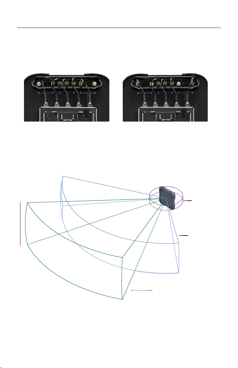
If using the Array Panel Antenna with your Bolt 4K 1500 or MAX receiver, you must
connect the five RP-SMA connectors from the receiver to the back of the antenna (see
below for connector placement), and position the antenna so that the front (with the
Teradek logo) has a clear line of sight to the transmitter.
V antenna only H+V configuration
The Array 4K panel has a built-in directional antenna with a receive pattern that
varies based on its distance from the transmitter. The horizontal receive angle
measures 55° at 5,000 ft (1.5 km), 104° at 4,000 ft (1.25 km), and is eectively
omni-directional at up to 500 ft (150 m). The vertical receive angle measures 20°
at any distance.
ARRAY PANEL ANTENNA
500 ft (150 m) ~ 360°
5,000 ft (1.5 km) ~ 55°
4,000 ft (1.25 km) ~ 104°
20°
For more information about the dierent antenna configurations for Bolt 4K, please
visit: https://www.teradek.com/blogs/articles/what-antennas-should-i-use-with-bolt-4k
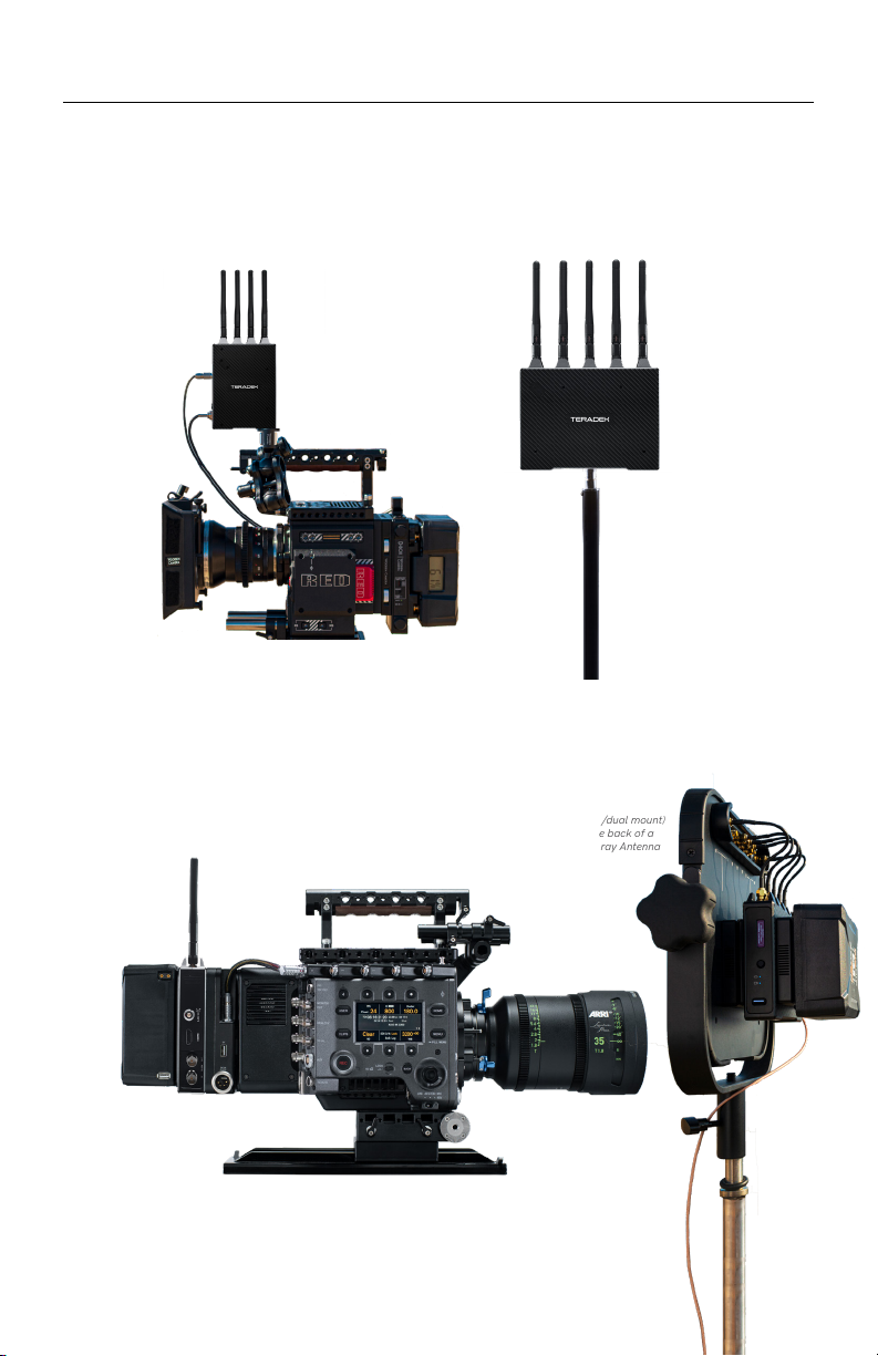
DEVICE PLACEMENT
Bolt 4K devices have a 1/4”-20 threaded hole (additional 3/8”-16 threaded hole
on the receiver) on the bottom for mounting the included light stand adapter or any
other mounting accessory.
WITH DUAL MOUNT
Depending on the model, Bolt 4K devices are equipped with a dual mount battery
plate that allows you to attach your device to either the back of a camera, monitor, or
Array 4K Panel Antenna.
Bolt 4K TX
mounts vertically
on a camera
WITHOUT DUAL MOUNT
Bolt 4K RX mounts
vertically on a light
stand or monitor
Bolt 4K TX (w/dual
mount) attaches to the
back of a camera
Bolt 4K RX (w/dual mount)
mounts on the back of a
monitor or Array Antenna
10

Teradek, LLC 2020. All rights reserved. v1.3-0620 11
STATUS SCREENS
TRANSMITTER DISPLAY OPERATION
● MAIN STATUS - Displays the status of the wireless receiver, along with
the current video resolution, frequency, and link
quality (if connected).
● INFO - Displays the current voltage and internal temperature
of the unit.
● HDMI STATUS - Displays the current HDMI color output
Bolt 4K’s configuration menus can be accessed from either the transmitter's front
panel display or from the Bolt app.
Press the menu joystick (G) to cycle through the status screens or to return from the
menu.
CONFIGURATION OPTIONS
The transmitter's Wireless Settings menu contains several configurable options to
optimize your transmitter's range, quality, and reliability.
WIRELESS SETTINGS - ENABLE BROADCAST MODE (BOLT K MAX)
Broadcast Mode allows you to transmit to multiple receivers simultaneously
(non-DFS frequencies only), while also extending Bolt 4K's transmission range.
WIRELESS SETTINGS
Most of the options listed in this section can also be configured using the Bolt app.
Use the Menu joystick (G) to navigate the transmitter's configuration options.
NOTE: Bolt 4K 750 and 1500 receivers will not link to a Bolt 4K MAX transmitter in
Broadcast Mode, even if they were previously paired.
● Broadcast Mode Disabled
(Standard Multicast Mode)
- Transmitter and connected receiver(s) coordinate
with each other to establish which frequency to use;
the transmitter communicates with the receiver via
a downlink data channel, while the receiver
maintains an uplink data channel to the transmitter.
● Broadcast Mode Enabled - Data uplink channel is disabled, allowing the
transmitter to connect to an unlimited number of
receivers, as long as they have already been paired.
To achieve even better range performance, attach
the receiver to your 4K Array Panel Antenna while
in Broadcast Mode.

WIRELESS SETTINGS - SELECT BANDWIDTH
The Bandwidth menu lets you choose between 40MHz (default) and 20MHz operating
modes. Ensure that both the transmitter and receiver are set to the same bandwidth
with a resolution of up to 1080p60. For all available frequencies, refer to the
FREQUENCIES BY REGION chart on page 25.
WIRELESS SETTINGS - SELECT FREQUENCY
The Frequencies menu contains a list of all available frequencies. Bolt 4K will
automatically select an operating frequency when multiple values are selected. If
both the transmitter and receiver have Fixed Frequency Mode enabled, you can only
select one frequency for Bolt 4K to use. Frequencies marked with (DFS) must be
scanned for one minute before they can be used, but are typically less crowded. For
all available frequencies, refer to the FREQUENCIES BY REGION chart on page 25.
12
WIRELESS SETTINGS - ENABLE FIXED FREQUENCY
Fixed Frequency Mode bypasses any automatic frequency switching logic, allowing
your Bolt 4K system to always attempt to connect on a specified frequency. Once
a frequency is selected, the transmitter will only use that frequency. This allows
your transmitter to link/reconnect to the receiver much faster. After enabling Fixed
Frequency mode, navigate to Frequencies and select a frequency not in use (non-DFS
frequencies only). For best results, ensure that both the transmitter and receiver have
Fixed Frequency Mode enabled, and use the Spectrum Analyzer (on the receiver's
front panel or the Bolt app) to search for the least congested frequency to use.
● Fixed Frequency Mode Disabled - Bolt 4K scans all available channels and
repeatedly switches from one frequency to
the next during transmission
● Fixed Frequency Mode Enabled - Bolt 4K connects to one specific frequency
● 20MHz - Reduces the amount of bandwidth by half, eectively doubling the
number of usable frequencies while decreasing interference
● 40MHz - (Default) Increases the amount of bandwidth by bonding two 20MHz
channels, allowing for faster transfer rates but increased interference
NOTE: 20MHz mode supports HD/3G resolutions up to 1080p60. Resolutions up to
4k30 are also supported, but downscaled to 1080p before transmission (4k50/59/60
is not supported).
NOTE: By default, Bolt 4K will select the lowest available frequency from the
Frequencies list if one has not been selected beforehand.

Teradek, LLC 2020. All rights reserved. v1.3-0620
WIRELESS SETTINGS - VIDEO QUALITY
The Video Quality menu lets you adjust the balance between your signal’s maximum
range and quality according to the number of antennas used to transmit fine
information. Bolt 4K has three picture quality levels that vary based on the lowest
quality link or the furthest receiver.
13
● Auto Mode - (Default) Transmitter automatically determines how
many fine antennas are needed based on the range and
signal quality
● Longer Distance Mode - (One fine antenna) Maintains the maximum range in
situations where other sources of interference might
be present, but will slightly reduce your video signal’s
maximum quality
● Better Quality Mode - (Two fine antennas) Maintains higher signal quality, but
reduces the maximum range
● Best Quality Mode - (Three fine antennas) Ideal for complex, high contrast
scenes that require the highest possible quality
● Low Power Mode - (One fine antenna with shorter range) Reduces the
transmitter's total power consumption by about 1.5W,
and may reduce any unwanted interference in multi-
system environments
PAIR
Enable pairing on transmitters and receivers. Bolt 4K units purchased as a set (TX
and RX) are paired by default, requiring no additional configuration. If the units were
purchased separately, or if they have never been paired, you will need to complete
the pairing process (page 5). Once Pairing is complete, there is no need to repeat the
process unless the TX or RX's OSD name has been modified, or if the region has been
changed. To confirm if your devices were paired successfully, open either the Unpair
menu (TX) or the Switch TX menu (RX) and verify that the paired device
is listed.
NOTE: Before starting the pairing process, ensure that both the transmitter and
receiver have the same firmware version and have Bluetooth enabled.
UNPAIR
Unpair and remove devices from your unit's paired device registry. This feature is
useful in situations when paired devices are no longer being used and need to either
be removed from the registry, or replaced. Transmitters can store up to six paired
receivers in its device registry.
DISPLAY SETTINGS
Use the Display Settings to control the OLED display operation. By default, the
OLED display will invert every 10 minutes. You can set the display to invert every 30
minutes (lengthens the display life), or it can dim or turn o after either 10 minutes or
10 seconds.
RESET ALL SETTINGS
Reset all configurable options to their factory defaults.
BLUETOOTH SETTINGS
Use the Bluetooth menu to enable or disable Bluetooth communication.
DEVICE INFO
Displays the model and serial number.
FIRMWARE VERSIONS
Displays the device's current firmware versions.
● Enable Bluetooth - Allows the transmitter and
receiver to be paired and
communicate with the
Bolt App
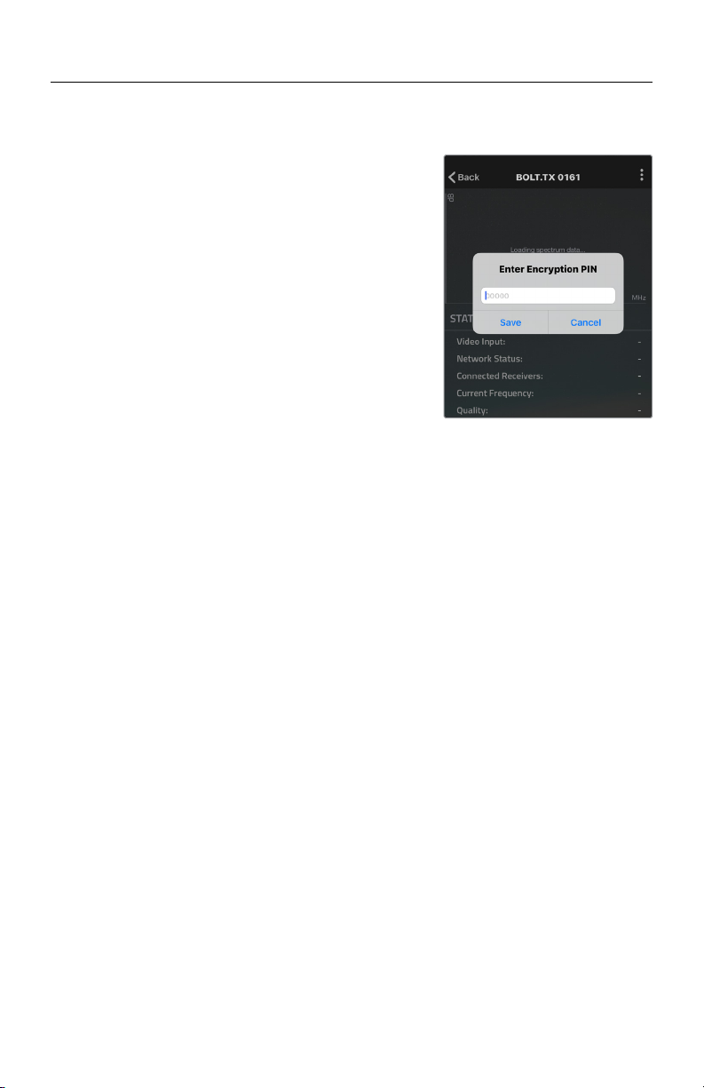
● Use Bluetooth PIN - Enables the use of a PIN for
authentication when using
the Bolt App (see image)
● Change PIN - Press the Menu joystick
towards the right to change
the Bluetooth PIN
NOTE: Bluetooth is disabled by default. In order to
configure your Bolt 4K devices via the Bolt App, you
must first enable Bluetooth.
● Invert every 30 min
● Dim every 10 min
● Dim after 10 sec
● Dim after 10 min
● O after 10 sec
● No BurnIn Prevention
14

Teradek, LLC 2020. All rights reserved. v1.3-0620
RECEIVER DISPLAY/OSD OPERATION
Bolt 4K’s configuration menus can be accessed from either the receiver's front panel
display or from the Bolt app. When enabled, the receiver’s configuration menus are
also displayed via On-Screen Display (OSD) on a connected monitor.
RECEIVER STATUS SCREENS
● MAIN STATUS - Displays the status of the wireless receiver, along with
the current video resolution, frequency, and link
quality (if connected).
● TIME CODE - Displays the current time code if received from the
transmitter.
● INFO - Displays the current voltage and internal temperature
of the unit.
● TX INFO - Displays the name of the transmitter it is paired to.
● HDMI STATUS - Displays the current HDMI color output
Press the menu joystick (G) to cycle through the status screens or to return from the
menu.
CONFIGURATION OPTIONS
Most of the options listed in this section can also be configured using the Bolt app.
Use the Menu joystick (G) to navigate the configuration menus.
SWITCH TX
Bolt 4K receivers can pair with up to four transmitters at a time. Switch TX allows
you to quickly switch from one paired transmitter's camera feed to another paired
transmitter. This feature is especially useful in multi-camera situations when you
need to switch to a dierent camera's view mid-shoot, without having to perform the
pairing process every time.
NOTE: The transmitter(s) need to first be paired with the receiver.
The transmitter's Wireless Settings menu contains several configurable options to
optimize your receiver's range, quality, and reliability.
WIRELESS SETTINGS
WIRELESS SETTINGS - ENABLE FIXED FREQUENCY
Fixed Frequency Mode bypasses any automatic frequency switching logic, allowing
your Bolt 4K system to always attempt to connect on a specified frequency. Once
a frequency is selected, the transmitter will only use that frequency. This allows
your transmitter to link/reconnect to the receiver much faster. After enabling Fixed
15

● Fixed Frequency Mode Disabled - Bolt 4K scans all available channels and
repeatedly switches from one frequency to
the next during transmission
● Fixed Frequency Mode Enabled - Bolt 4K connects to one specific frequency
NOTE: By default, Bolt 4K will select the lowest available frequency from the
Frequencies list if one has not been selected beforehand.
Frequency mode, navigate to Frequencies and select a frequency not in use (non-DFS
frequencies only). For best results, ensure that both the transmitter and receiver have
Fixed Frequency Mode enabled, and use the Spectrum Analyzer (on the receiver's
front panel or the Bolt app) to search for the least congested frequency to use.
WIRELESS SETTINGS - SELECT BANDWIDTH
The Bandwidth menu lets you choose between 40MHz (default) and 20MHz operating
modes. Ensure that both the transmitter and receiver are set to the same bandwidth
with a resolution of up to 1080p60. For all available frequencies, refer to the
FREQUENCIES BY REGION chart on page 25.
WIRELESS SETTINGS - SELECT FREQUENCY
The Frequencies menu contains a list of all available frequencies. Bolt 4K will
automatically select an operating frequency when multiple values are selected. If
both the transmitter and receiver have Fixed Frequency Mode enabled, you can only
select one frequency for Bolt 4K to use. Frequencies marked with (DFS) must be
scanned for one minute before they can be used, but are typically less crowded. For
all available frequencies, refer to the FREQUENCIES BY REGION chart on page 25.
● 20MHz - Reduces the amount of bandwidth by half, eectively doubling the
number of usable frequencies while decreasing interference
● 40MHz - (Default) Increases the amount of bandwidth by bonding two 20MHz
channels, allowing for faster transfer rates but increased interference
NOTE: 20MHz mode supports HD/3G resolutions up to 1080p60. Resolutions up to
4k30 are also supported, but downscaled to 1080p before transmission (4k50/59/60
is not supported).
16

Teradek, LLC 2020. All rights reserved. v1.3-0620
SPECTRUM ANALYZER
The built-in Spectrum Analyzer provides a visual indication of channel noise and
saturation across the entire available frequency range. Move the Menu joystick left
and right to select a frequency, then up and down to enable or disable it.
3
2
1
Frequencies are represented by bars; the higher the bar, the more congested that
frequency is. Bars without a dot (1) indicate the frequency is not as saturated and
can be used. Bars with a dot (2) indicate the frequency is too saturated to connect to.
Faded bars (3) represent a frequency that is unavailable for use due to restrictions in
particular regions.
SIGNAL QUALITY GRAPH
The Signal Quality Graph indicates the quality and reliability of the signal being
received according to the amount of interference that is present between the RX and
TX. Signal Quality is represented in percentages:
● Figures below 30% indicate poor signal quality
● Figures between 30% and 45% indicate fair signal quality
● Figures above 45% indicate good signal quality
PAIR
Enable pairing on transmitters and receivers. Bolt 4K units purchased as a set (TX
and RX) are paired by default, requiring no additional configuration. If the units were
purchased separately, or if they have never been paired, you will need to complete
the pairing process (page 5). Once Pairing is complete, there is no need to repeat
the process unless the TX or RX's OSD name has been modified, or if the region has
been changed. To confirm if your devices were paired successfully, open the either
the Unpair menu (TX) or the Switch TX menu (RX) and verify that the paired device is
listed.
NOTE: Before starting the pairing process, ensure that both the transmitter and
receiver have the same firmware version and have Bluetooth enabled.
UNPAIR
Unpair and remove devices from your unit's paired device registry. This feature is
useful in situations when paired devices are no longer being used and need to either
be removed from the registry, or replaced. Receivers can store up to four transmitters
in its device registry.
17

● 3D LUT Presets - Select a specific look from the list of 3D LUT presets.
● 3D LUT Mode - Select whether the look is applied to the entire video
output (Full Screen) or half (Split Screen).
3D LUT SETTINGS
The 3D LUT settings menu contains specific looks that can be applied to your video
output that either match or simulate how the video will appear after editing, along
with options for how they are overlayed on your video output (Full or Split screen).
Additional color preset files can be added and saved from your computer using Bolt
Manager (page 21).
HDMI SETTINGS
Bolt 4K supports all HDMI output modes. You can select from one of the following
options:
● Auto
● RGB 8bit
● RGB 10bit
● YCbCr 4:4:4 8bit
● YCbCr 4:4:4 10bit
● YCbCr 4:2:2 10bit
● YCbCr 4:2:0 8bit
● YCbCr 4:2:0 10bit
HDMI/SDI OUT FORMAT
You can choose to match the video source’s resolution (Same As Input), or choose
from the resolutions listed. If using the receiver with a recorder or monitor that is
sensitive to video signal changes, select Continuous Output to ensure the signal
stays constant even if the link is interrupted. Keep in mind that selecting Continuous
Output adds a small delay to the video output. Selecting SD, HD, or 6G-UHD
matches the video source's frame rate while adjusting the resolution. This is useful
for when you need to down-convert a 4K video to display on an HD monitor.
● Continuous Output - Video signal output stays constant when using a
monitor or recorder that is sensitive to video signal
changes
● Same As Input - Matches the transmitter’s video source resolution.
● SD - Matches the TX frame rate and outputs SD resolution
● HD - Matches the TX frame rate and outputs1920x1080p
● 6K-UHD - Matches the TX frame rate and outputs 3840x2160
● Resolutions List - Select a specific output resolution:
● 4K (DCI) - 23.98/24/25/29.97/30/50/59.94/60
● 4K (UHD) - 23.98/24/25/29.97/30/50/59.94/60
● 1080p - 23.98/24/25/29.97/30/50/59.94/60
● 1080psf - 23.98/24/25/29.97/30
● 1080i - 50/59.94/60
● 720p - 50/59.94/60
● 480p - 59.94/576p - 50 (via HDMI ports only)
● 480i (NTSC)
● 576i (PAL)
18
This manual suits for next models
2
Table of contents
Other Teradek Microphone System manuals


