Elpro Technologies EL-415U-IAS-C Series User manual

ELPRO_415U-IAS_IntelligentAntennaSwitch_UserManual_1.0.docx
ELPRO Technologies
29 Lathe Street
Virginia QLD 4014
Australia
tel: +61 7 3352 8600
www.elpro.com.au
415U-IAS Intelligent Antenna Switch User Manual
Contents
Introduction......................................................1
System Design................................................2
Redundancy ................................................2
Connection to the SCADA computer...........2
Connection to the Legacy Base Radio........2
Configuration...................................................3
415U-BSR (Base Station and Repeater)
Configuration ...............................................3
MODBUS Migration Router configuration3
SCADA Computer RS-232 Serial
connection................................................4
Multicast Pipe Manager Configuration.....4
Legacy Base Radio Connection ..............4
SCADA Computer TCP-IP Ethernet
connection................................................4
415U-E and 415U-C Field Station
Configuration ...............................................5
Field Station Serial Connection ...............5
Diagnostics .....................................................6
LED indication on 415U-IAS .......................6
415U-BSR Internal Diagnostics ..................6
Serial Connection Statistics.....................6
Capture IP Comms..................................6
Connection......................................................7
Rear Panel Connections .............................7
RS232 DTE –DB9 Male (DTE)...............7
RS-485 and Power –4-way Connector
5.08mm....................................................7
RF Switch 1 and RF Switch 2..................7
Earth........................................................7
Front Panel Connections.............................8
Scada Computer –DB25 Female - DCE.8
Legacy Radio –DB25 Male - DTE ..........8
Specifications –ELPRO 415U-IAS.................9
References:.....................................................9
Introduction
The ELPRO 415U-IAS provides a way to operate two radio telemetry systems side by side using
existing infrastructure. The primary use-case is when an existing system is being incrementally
upgraded to ELPRO 415U radio hardware. The 415U-IAS automatically switches the base station
antenna between a legacy base station radio and the upgraded base station radio as needed to
communicate with a mix of legacy and upgraded radios in the field.
The 415U-IAS switch module is used in conjunction with an ELPRO 415U-BSR (Base Station and
Repeater) which monitors the polling requests sent to the remote field stations and instructs the
switch module to connect the required base station radio (Legacy or 415U-BSR) to the antenna.
Responses from field stations are monitored, and the switch will alternate between the two systems
when it doesn’t see a valid response from a field site. This allows incremental upgrades of field sites
without a need to make configuration changes when field sites are switched from the legacy system to
the new 415U system.

Page 2 of 9 November 2021
ELPRO_415U-IAS_IntelligentAntennaSwitch_UserManual_1.0.docx
System Design
The 415U-IAS is designed to be installed with an existing legacy system. The 415U-BSR monitors
MODBUS messages sent from a central SCADA computer and monitors MODBUS responses from
field sites. The system can use either RS-232 serial communications or it can communicate over
TCP-IP link.
The legacy system must use MODBUS protocol, and the radio network must be a polling-only system
(No background communications between the legacy base station and legacy field sites).
The process for system upgrade is:
1) Install the 415U-IAS and 415U-BSR at the base station
2) Connect to the SCADA computer and the Legacy Base Radio
3) Ensure the Legacy system is operating correctly, with all existing sites remaining operational.
The 415U-IAS will switch to the Alternate port each time a message is sent to a Legacy site.
4) Begin upgrading Legacy radios with new ELPRO 415U series radios. As each site is
upgraded, the Base station should detect the change, and the 415U-IAS should switch to the
Primary port when polling the ELPRO 415U series radios.
Redundancy
Some systems require a level of redundancy to support increased reliability. Once the system
upgrade is complete, the ELPRO 415U system provides hot standby redundancy. During the system
upgrade, the 415U-BSR is set up for cold standby. Only one of the two radios in the 415U-BSR is
powered at any time. The two RF Switches on the 415U-IAS operate together. To switch to the
standby 415U-BSR radio, switch the connections on the rear panel from the “Repeater 1” connections
to the corresponding “Repeater 2” connections.
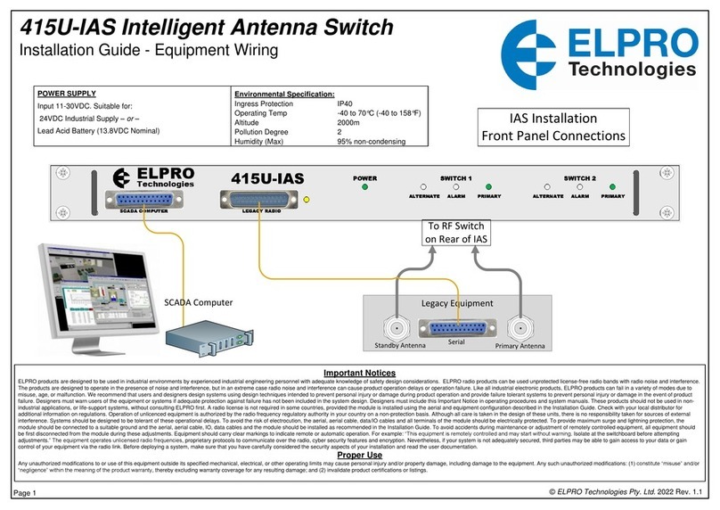
If a redundant system is being implemented, then connect both RF Switches on the 415U-IAS. If
redundancy is not to be implemented, then only connect to RF Switch 1. Refer to the install guide for
a detailed diagram for connecting redundant systems.
Connection to the SCADA computer
Most existing systems will be using an RS-232 serial connection between the SCADA computer and
the Legacy base radio. The 415U-IAS allows either RS-232 communications or communication over a
TCP-IP stream.
To connect to the SCADA computer using RS-232 serial, connect to the DB-25 female connector
marked “SCADA Computer” on the front of the 415U-IAS unit. Data to and from the SCADA computer
is transferred to the 415U-BSR RS-485 serial port. Ensure the data rate and character format on the
415U-BSR RS-485 serial port match the data rate of the SCADA computer (See “SCADA Computer
RS-232 Serial connection ” on page 4 below).
To connect to the SCDA computer using TCP-IP stream, connect the Ethernet cable to the ethernet
port on the 415U-BSR (See “Multicast Pipe Manager Configuration” on page 4 below).
Connection to the Legacy Base Radio
Connect the Legacy Base Radio to the DB-25 Male plug on the front of the 415U-IAS marked “Legacy
Radio”. When the Legacy radio is a DB-25 Female (DCE), you can connect using a standard DB-25
extension cable. When the Legacy radio is turned on and the connection is made, the yellow LED
marked “ACT” will come on and will flicker with traffic between the 415U-IAS and the Legacy Radio.
Messages to and from the legacy radio are sent and received on the 415U-2 BSR RS-232 serial port.
Ensure the data rate on the 415U-BSR RS-232 serial port to match the data rate of the Legacy Base
Radio (See “MODBUS Migration Router configuration” on page 3 below).

Page 3 of 9 November 2021
ELPRO_415U-IAS_IntelligentAntennaSwitch_UserManual_1.0.docx
Configuration
This section covers the configuration required on the 415U-BSR and the Remote sites for a system
update with the 415U-IAS.
415U-BSR (Base Station and Repeater) Configuration
The 415U-BSR controls the 415U-IAS switching between Primary and Alternate ports, and transfers
data messages from the SCADA computer to the Legacy base radio and to the ELPRO 415U radio
network. This section describes how to configure the 415U-BSR that relate to the 415U-IAS operation.
Refer to the separate user manual for the 415U-BSR for other configuration items. Refer to Figure 1-
415U-BSR Functional Elements below to see how the four configuration elements are related.
Figure 1- 415U-BSR Functional Elements
The configuration items for the operation of the 415U-IAS are on the Serial configuration page. Select
“Full Configuration” under “Advanced” on the right-side menu, then select “Serial” under
“Configuration”. To set up for 415U-IAS operation, configure the RS-232 serial port, the RS-485 serial
port, the MODBUS Migration Router and the Multicast Pipe Manager.
MODBUS Migration Router configuration
The Modbus Migration Router receives Modbus polls from the SCADA computer, and forwards these
messages to either the ELPRO 415U radio network (via the Multicast Pipe Manage) or the Legacy
radio network (via the RS-232 Serial Gateway). First check “Enabled” to enable the configuration,
then select the Master Port and Slave Port.
Master Port The port used for the connection to the SCADA computer
Slave Port The port used for the connection to the radio networks.
Max failed polls The number of times a remote site will fail to respond before the Migration router
switches to the alternate port for that slave.
Main Port Dwell Time The minimum amount
of time the switch will remain on
the Primary position
Main Port Tail Time The amount of time
the switch will remain on the
Primary position after completing
message transmission on that
Port
Aux Port Tail Time The amount of time
the switch will remain on the
Alternate position after
completing message
transmission on that Port
RS-485 Serial Gateway
RS-485
Serial Port
From
SCADA
TCP-IP
Client
MODBUS Migration
Router
Master Port
Slave Port
RS-232 Serial Gateway
RS-232 Serial
Port
TCP-IP
Client
To Legacy
Radio Network
Multicast Pipe Manager
UDP-IP
Multicast
TCP-IP
Client
To ELPRO
Radio Network

Page 4 of 9 November 2021
ELPRO_415U-IAS_IntelligentAntennaSwitch_UserManual_1.0.docx
SCADA Computer RS-232 Serial connection
When the connection to the SCADA computer is
via RS-232 serial, the SCADA computer
connection is through the 415U-IAS and via the
RS-485 connection on the 415U-BSR. Configure
the 415U-BSR RS-485 serial port to match the
SCADA computer serial connection. Configure
RS-485 Port Type to “Serial Gateway”. Set the
data rate and data format to match the
configuration for the SCADA computer. Set Serial
Gateway Mode to “TCP Client”. Set the Remote
Device IP Address to 127.0.0.1 to address the
local unit. Set the Remote Device Port match the
Master port on the Modbus Migration Router.
Multicast Pipe Manager Configuration
The Multicast Pipe Manager provides the
connection to the ELPRO 415U radio network. Set
the network mode to Client. Set the Remote
Device IP Address to 127.0.0.1 to address the
local unit. Set the Remote Device Port to match
the Slave Port on the Modbus Migration Router.
Set the Multicast Group IP Address and Port to
match the configuration for the ELPRO 415U
Radio network. Multicast Group IP Addresses are
in the range 224.0.1.1 through 239.255.255.255.
Select “Disable AP Bridge” to reduce radio traffic.
Legacy Base Radio Connection
The Legacy Base Radio serial port connects to the
RS-232 serial port on the 415U-BSR through the
415U-IAS. Configure the 415U-BSR RS-232 serial
port to match the Legacy Base Radio serial port
configuration. Configure RS-232 Port Type to
“Serial Gateway”. Set the data rate and data
format to match the configuration for the Legacy
Base Radio. Set Serial Gateway Mode to “TCP
Client”. Set the Remote Device IP Address to
127.0.0.1 to address the local unit. Set the Remote
Device Port match the Slave port on the Modbus
Migration Router.
SCADA Computer TCP-IP Ethernet connection
When the connection to the SCADA computer is
via Ethernet connection (TCP-IP), configure the
415U-BSR Networking to allow the connection by
disabling the RS-485 port.
Configure the SCADA computer connection to connect to the IP address of the 415U-BSR (Network
Configuration Page) and to connect to the Master port on the Modbus Migration Router.

Page 5 of 9 November 2021
ELPRO_415U-IAS_IntelligentAntennaSwitch_UserManual_1.0.docx
415U-E and 415U-C Field Station Configuration
The field station units must be configured to allow MODBUS communication from the connected
device back to the Multicast Pipe Manager active in the 415U-BSR. Configure the RS-232 or RS-485
port as described below to communicate with the connected device on the corresponding port.
Field Station Serial Connection
This example shows configuration for RS-485
serial. The steps are identical for RS-232.
Configure Port Type to “Serial Gateway”. Set
the data rate and data format to match the
connected MODBUS device. Set Serial
Gateway Mode to “UDP Multicast”. Set the
Multicast Group IP address and Port to match
the Multicast Group settings in the 415U-BSR
(see Multicast Pipe Manager Configuration on
page 4). Character timeout and Packets Size
will normally operate correctly with the default
values. See the 414U-2, 415U-E User manual
for more detail on setting these items.

Page 6 of 9 November 2021
ELPRO_415U-IAS_IntelligentAntennaSwitch_UserManual_1.0.docx
Diagnostics
LED indication on 415U-IAS
The 415U-IAS unit provides LEDs to indicate the status of the unit.
LED
Colour
Function
Power
Green
Indicates power connected to the 415U-IAS unit
Alternate
Green
Indicates the RF switch (Switch1 or Switch2) is connected between ANT and
Alternate ports on the rear panel. This is the connection used for the Legacy
radio network.
Primary
Green
Indicates the switch (Switch1 or Switch2) is connected between ANT and
Primary ports on the rear panel. This is the connection used for the ELPRO
415U radio network.
Alarm
Red
Indicates the IAS attempted to switch RF ports while the connected radio
(Legacy or ELPRO 415U) was sending data through the active port. This
LED should not come on unless there is a problem with the system
configuration resulting in the RF switching at the wrong time.
Legacy
ACT
Yellow
Indicates the Legacy radio is connected and powered on. The LED will
flicker with serial data from the Legacy radio through the IAS to the BSR.
RS232
DTE ACT
Yellow
Indicates the BSR RS-232 serial is connected and the BSR is powered on.
This port is used to transfer the messages for the Legacy radio network. This
LED will flicker when there is serial data from the 415U-BSR through the IAS
to the Legacy radio.
415U-BSR Internal Diagnostics
The 415U-BSR provides internal webpages providing a wide range of diagnostic information. This
section describes the diagnostic information relating to the operation of the 415U-IAS. Additional
information on operation of the 415U-BSR is described in the separate user manual for that product.
Serial Connection Statistics
Access this page by
selecting Statistics under
Unit Diagnostics. Scroll
down to the panel “Serial
Connection Statistics”.
This panel provides
details on the status of the
connection. You can view
the active field devices
under “Slave Port
Connections”. ELPRO
415U devices are listed
under “Main Port” and
legacy radio network
devices under “Legacy
Port”.
Capture IP Comms
This feature is available by selecting “Capture IP Comms” under “Network Diagnostics” on the right-
side menu. It provides a useful diagnostic tool to view messages between the Multicast Pipe Manager
and the ELPRO radio network. These messages will have the Multicast IP address configured in
“Multicast Pipe Manager Configuration” and in “Field Station Serial Connection”. When the SCADA
computer connection is via TCP-IP, this will also show the communication between the SCADA
computer and the Modbus Migration Router (see SCADA Computer TCP-IP Ethernet connection on
page 4 above).

Page 7 of 9 November 2021
ELPRO_415U-IAS_IntelligentAntennaSwitch_UserManual_1.0.docx
Connection
Rear Panel Connections
This section provides a detailed reference on the 415U-IAS rear panel connections.
RS232 DTE –DB9 Male (DTE)
1
2
3
4
5
6
7
8
9
Pin#
Abbrev
Signal Name
Direction
Required
Notes
1
-
No Connection
2
RD
Received Data
To DTE
Yes
Receive to DTE
3
TD
Transmitted Data
From DTE
Yes
Transmit from DTE
4
DTR
Data Terminal Ready
From DTE
Loop from DSR pin 9
5
SG
Signal Ground
<->
Yes
Reference Ground for signals
6
-
No Connection
7
RTS
Request to Send
From DTE
Loop from CTS pin 8
8
CTS
Clear to Send
To DTE
Loop to RTS pin 7
9
DSR
Data Set Ready
To DTE
Control for RF Switch.
Low: Primary
High: Alternate
Loop to DTR pin 4
RS-485 and Power –4-way Connector 5.08mm
Pin#
Abbrev
Signal Name
Direction
Notes
1
B
RS485 “B”
Bidirectional
Negative Sense RS485 signal
2
A
RS485 “A”
Bidirectional
Positive Sense RS485 signal
3
“-“
Power Negative
Into Unit
Internal Connection to Earth
4
“+”
Power Positive
Into Unit
9 –30VDC Power 100mA.
RF Switch 1 and RF Switch 2
Signal Name
Connection
Notes
Primary
To ELPRO 415U Base antenna connection
50ΩMaximum input 10W
Ant
To Shared System Antenna
50Ω impedance
Alternate
To Legacy Base Radio antenna connection
50ΩMaximum input 10W
Earth
This is the protection earth for the unit and should be connected to a reliable earth point, such as a
building earth or external earth stake. Resistance to ground should be less than 2Ω, and must not be
more than 5Ω.

Page 8 of 9 November 2021
ELPRO_415U-IAS_IntelligentAntennaSwitch_UserManual_1.0.docx
Front Panel Connections
This section provides a detailed reference on the 415U-IAS front panel connections.
Scada Computer –DB25 Female - DCE
13
12
11
10
9
8
7
6
5
4
3
2
1
25
24
23
22
21
20
19
18
17
16
15
14
Pin#
Abbrev
Signal Name
Direction
Required
Notes
1
FG
Frame Ground
<->
Connected to Chassis Gnd
2
TD
Transmitted Data
To DCE
Yes
Transmit from DTE
3
RD
Received Data
From DCE
Yes
Receive to DTE
4
RTS
Request to Send
To DCE
Loop to CTS pin 5
5
CTS
Clear to Send
From DCE
Loop from RTS pin 4
6
DSR
Data Set Ready
From DCE
Loop from DTR pin 20
7
SG
Signal Ground
<->
Yes
Reference Ground for signals
8
DCD
Data Carrier Detect
From DCE
Loop from DTR, pin 20
9-19
-
No Connection
20
DTR
Data Terminal Ready
To DCE
Loop to DSR, DCD, Pins 6,8
21-25
-
No Connection
Legacy Radio –DB25 Male - DTE
1
2
3
4
5
6
7
8
9
10
11
12
13
14
15
16
17
18
19
20
21
22
23
24
25
Pin#
Abbrev
Signal Name
Direction
Required
Notes
1
FG
Frame Ground
<->
Connected to Chassis Gnd
2
TD
Transmitted Data
From DTE
Yes
Transmit from DTE
3
RD
Received Data
To DTE
Yes
Receive to DTE
4
RTS
Request to Send
From DTE
Loop from CTS pin 5
5
CTS
Clear to Send
To DTE
Loop to RTS pin 4
6
DSR
Data Set Ready
To DTE
Loop to DTR, pin 20
7
SG
Signal Ground
<->
Yes
Reference Ground for signals
8-19
-
No Connection
20
DTR
Data Terminal Ready
From DTE
Loop from DSR, pin 6
21-25
-
No Connection

Page 9 of 9 November 2021
ELPRO_415U-IAS_IntelligentAntennaSwitch_UserManual_1.0.docx
Specifications –ELPRO 415U-IAS
ELPRO 415U-IAS-C1, -C4, -C9
Power Supply
9-30VDC 100mA. Internal fuse protection.
Serial Connections
4 Serial Connections
RS232 DTE
DB9 DTE to 415U-BSR
Legacy Radio
DB-25 DTE to Legacy Base Radio
SCADA Computer
DB-25 DCE to SCADA computer
RS-485
RS-485 to 415U-BSR
RF Ports
2 Absorptive SPDT Switches.
Primary, Alternate
50 ΩConnection to radio
10W maximum power
50Ωtermination when disconnected from ANT
Power detection and Protection from Switching while carrying power
Internal Surge protection provides additional protection for surges
coming from the Antenna port.
ANT
50Ω connection to Antenna.
Internal Surge protection. Additional Protection recommended when
connected to exposed antenna.
LED Indication
Showing status for both switches including Alarm status.
RF Operating Band
415U-IAS-C1
148-170MHz
415U-IAS-C4
400-540MHz
415U-IAS-C9
890-960MHz
References:
415U-IAS Installation Guide inst_415U-IAS_V1.0
415U-BSR User Manual EL-MN-415-BSR_V1.1
415U-BSR Installation Guide EL-IL-415-BSR-R1.1
415U-2, 415U-E User Manual 415U_UserManual_v2-20
Other manuals for EL-415U-IAS-C Series
1
This manual suits for next models
4
Table of contents
Other Elpro Technologies Switch manuals
