Elsist SlimLine Picoface User manual
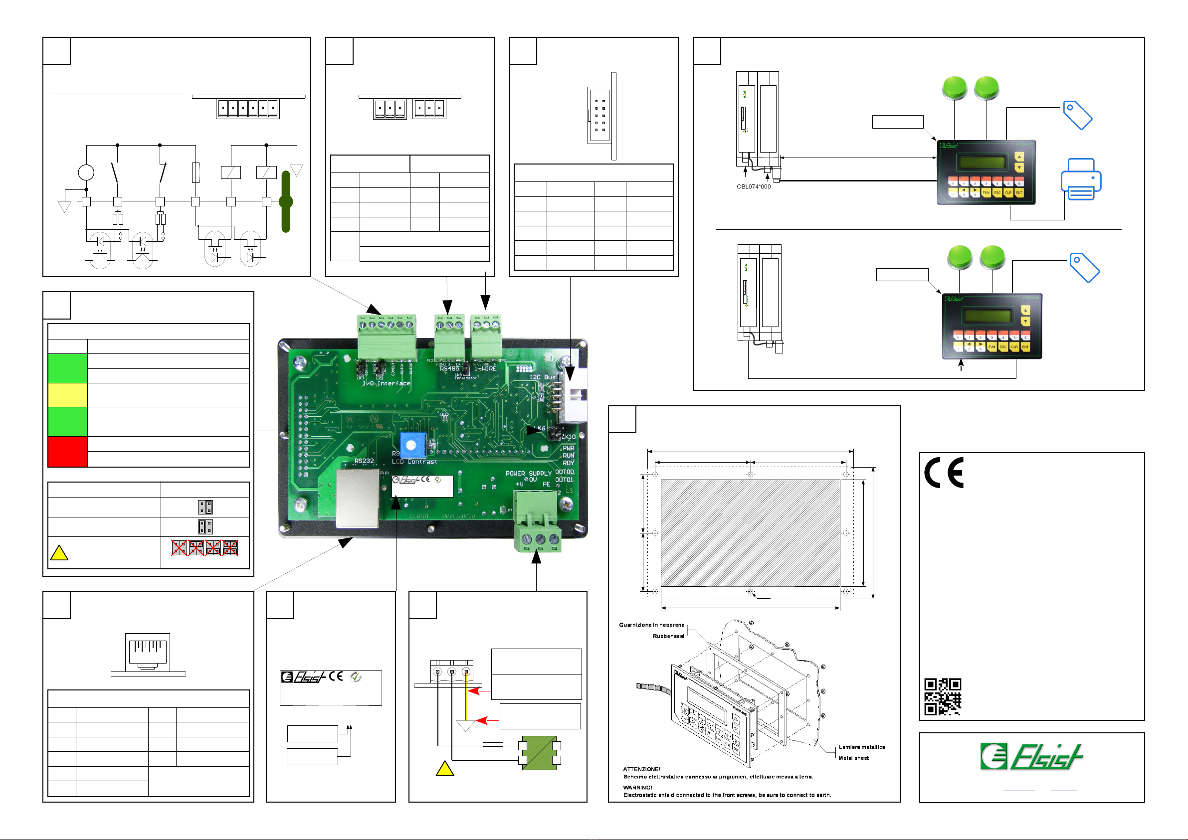
RS485 (P12) 1-Wire (P5)
Pin Signal Pin Signal
1 D+ 1 Data
2 D- 2 GND
3 Field GND 3 N.C.
LK9 ON= Line Terminated (120 Ohm)
ust be inserted if used in RS232
2
13
P5
13
P12
9
LBL052E 000
C o d e :
O I F 0 2 3 A 1 0 0
S e r i a l N r :
0 0 1 6 3
Via G. Brodolini, 15 (Z.I.) 15033 CASALE .TO (AL) ITALY
Phone +39-0142-451987 Fax +39-0142-451988
Internet: http://www.elsist.it email: [email protected]
SlimLine
SlimLine
Picoface HM
Picoface HM
Hardware
Hardware
Manual
Manual
NL181A110
CPU Status
LED Function
PWR
(Green)
ON=Power OK
OFF= Power fault
RUN
(Yellow) Regular Blink = System OK
RDY
(Green)
ON=System Ready
OFF=System Stopped
OUT0x
(Red)
ON=Out 0X ON
OFF=Out 0X OFF
Mode LK6/LK10
Normal operation (Default)
Firmware upgrade
Not allowed!
BUS 2C (P6)
Pin Signal Pin Signal
1 +5Vdc 6 GND
2 +5Vdc 7 SCL
3 +5V (Aux) 8 GND
4 +5V (Aux) 9 SDA
5 RDY-N 10 GND
5
3
6 Dima di foratura
Template dimension
41
6 5 4 3 2 1
DICom
DI01
DOCom
DO01
DO00
+
-
Vmax=30Vdc
Fuse 250mAFF
0,025A2s
PLC F ELD
P4
DI00
LK2
LK3
16
P4
19
10 2
P6
RS232 (COM0 P1)
Pin Signal Pin Signal
1 Not connected 6 TX
2 Not connected 7 CTS
3 DTR 8 RTS
4 GND
5 RX
1 8
P1
7Porta RS232
RS232 Port
L B L 0 5 2 E 0 0 0
Code:
O I F 0 2 3 A 1 0 0
S e r i a l N r :
0 0 1 6 3
OIF023**00
Livello modulo
odule release
Base version = 0
Full version = 1
8dentificazione
dentification
Alimentazione (Vers. Full)
Power supply (Full vers.)
+
-
~
~
~
=
Fuse 1AT
Vmax=30Vdc
Tenere corto e distante
da fonti di disturbo
2,5mm2
12AWG essa a terra pulita
Clean GND
P2
13
Keep it short and away
from noise sources
!
Bus estensione
Extension Bus
63,5mm 63,5mm
39mm 39mm
119mm
71mm
137mm
88mm
3,5mm
Connessioni possibili
Possible connections
LK10
LK6
LK10
LK6
!
LK6
LK10
/O Digitali
Digital /Os
Bus di campo
Field bus
LK2-3: to plug for 5V operation
WARN NG! Do not apply more than 6Vdc on input
set for 5V operation.
LK2-3: Inserire per funzionamento
ingresso a 5V
ATTENZ ONE! Non applicare tensioni maggiori di
6Vdc sugli ingressi settati per funzionamento a 5V.
USB SD CARD
PWR
RDY
R U N
C P U
I/O odule
RS232/485
1-Wire Bus
10-30Vdc
TAG ID
Push Buttons
OIF023*100
USB SD CARD
PWR
RDY
R U N
C P U
I/O odule
RS232
ax. 1,5mt
I
2
C Bus
1-Wire Bus
CBL045*110
Printer
TAG ID
Push Buttons
OIF023*000
Stato – Upgrade
Status - Upgrade
Technical Specifications
Device Version Base Full
Power Supply 5Vdc 150mA max. (worst case)
From extension bus
10-30Vdc 1W (worst case without devices
connected on I2C bus)
Power to extension bus None 5V 0.7A max.
Processor NXP LPC1115 (Cortex 0)
1-Wire Interface 1
RS232 Interface 1 * DTE on RJ45 connectors (Shared with RS485)
RS485 Interface 1* Fail Safe, High impedance RS485 (allows up to 128 device on the same net) (Shared with RS232)
Display STN 2*16 characters alphanumeric LED back light
Keyboard 16 membrane Keys 7 of which equipped w. LED customizable
Digital Input 2 Optoisolated PNP 10-30Vdc, 7mA@24V (may be set for 5V operation by jumper)
Digital Output 2 photo OS 0.25A@40Vdc/ac (TOn=0,75mS max, TOff=0,2mS max)
Status Indicators Power, RUN, READY, Output
Expansion bus I2C™ Fast Speed
Environment Operating temperature : from -20 to +70°C
Storage temperature: from -40° to +80°C
Relative Humidity: ax. 90%
Dimensions and weight
137 mm L x 88 mm W x 37 mm H 137 mm L x 88 mm W x 40 mm H
Weight: 80g Weight: 100g
Approvals EN 61000-6-2:2005, EN 61000-6-4:2007
Notes
Connessioni
Picoface H I è dotato di morsetti estraibili per la connessione
dell’alimentazione (ove prevista), I/O e Bus di campo, connettore
IDC per il collegamento dei bus di estensione I2C, e di connettore
RJ45 per il collegamento della porta RS232.
Alimentazione (Fig. 9)(solo versione full)
Il dispositivo può essere alimentato con una tensione continua
compresa nell’intervallo 10-30V. La connessione della
alimentazione deve essere effettuata in accordo alla Fig. 9.
La presenza della tensione di alimentazione è segnalata dal
LED verde “PWR”.
ATTENZ ONE! l superamento del valore massimo di
tensione indicato può provocare il danneggiamento
irreversibile dell’apparato.
Collegamento di terra (Fig. 9)
Il dispositivo deve essere collegato direttamente a terra
mediante l'apposito morsetto del connettore di alimentazione (Fig.
9).
Il collegamento deve essere eseguito mediante una cordina
avente sezione di almeno 2.5 mm2, ad una barra equipotenziale di
rame di adeguata sezione.
Al fine di garantire una buona rejezione ai disturbi, è
necessario che questo collegamento sia mantenuto il più corto
possibile e non venga fatto passare con altri cavi.
/O Digitali (Fig. 1)
Il dispositivo è provvisto di 2 ingressi digitali e 2 uscite digitali,
galvanicamente isolati dal sistema.
Gli ingressi, di tipo PNP, possono, attraverso l'inserimento dei
rispettivi ponticelli, acquisire segnali digitali a 5Vdc.
ATTENZ ONE! Non applicare tensioni superiori a 6V
sugli ingressi settati a 5Vdc.
Le uscite sono di tipo opto- OS e possono essere
indifferentemente di tipo PNP o NPN.
ATTENZ ONE! Eventuali cortocircuiti sulle uscite
digitali possono provocare il danneggiamento
irreversibile dell'apparato. E' consigliabile inserire un
fusibile extra rapido 200mAFF in serie al comune. Out,
(es. Ferraz G084002P).
Bus di estensione (Fig. 3)
Il bus di estensione I2C permette la connessione del
dispositivo, limitatamente alla versione base, alle CPU SlimLine e
Netsyst III, ed è disponibile su connettore IDC 10 poli (P6).
Possono essere connessi più dispositivi Picoface H I allo
stesso bus, purché non si superi la lunghezza massima del cavo di
estensione di 1,5mt.
In figura 4 sono schematizzati i possibili collegamenti dei
terminali alle CPU.
ATTENZ ONE! Prima di collegare il/i terminali al
modulo CPU, accertarsi che questo non sia
alimentato. n caso contrario i dispositivi potrebbero
essere irrimediabilmente danneggiati.
Porta seriale RS232 (Fig. 7)
Picoface dispone di una porta seriale di tipo “DTE” (Data
Terminal Equipment).
Nella versione “Full” la porta seriale viene utilizzata per
connettere il terminale alla CPU (SlimLine e Netsyst III), mentre,
nella versione “Base”, la porta RS232 viene vista com CO
aggiuntiva del sistema.
La porta RS232 è condivisa con la RS485 (Vedi Fig. 2)
La porta RS232, non è galvanicamente isolata dal sistema,
quindi è opportuno verificare, prima di collegare tra di loro
dispositivi RS232 diversi, che il loro potenziale di massa sia lo
stesso.
ATTENZ ONE! Differenze di potenziale eccessive tra
punti di massa diversi, possono causare
danneggiamenti irreversibili ai dispositivi.
Bus di campo (Fig. 2)
Il dispositivo è dotato di bus di campo RS485. La porta RS485
è condivisa con la porta CO RS232.
Per il collegamento del bus RS485 attenersi alla figura a lato.
Attraverso il jumper LK9 può essere inserita la resistenza di
terminazione 120 Ohm o meno.
Il dispositivo è dotato anche di bus 1-WireT , attraverso al
quale è possibile l'acquisizione di dispositivi i-ButtonT , quali TAG di
identificazione personale e sensori di temperatura.
Segnalazioni stato (Fig. 5)
Il dispositivo è dotato di LED per la segnalazione dello stato di
funzionamento, in particolare è segnalato lo stato di:
·PWR (LED Verde)
Indica la presenza dell’alimentazione
·RUN (LED Giallo)
Lampeggiante regolare indica che il sistema è in funzione,
·RDY (LED Verde)
Acceso indica che il sistema è pronto e funzionante.
·OUT0x (LED Rosso)
Acceso indica che l'uscita digitale corrispondente è attiva.
Compatibilità elettromagnetica
Il dispositivo è conforme alla direttiva compatibilità
elettromagnetica in accordo con la norma EN 61000-6-4:2007
(Norma generica sull’emissione riguardante ambienti industriali) e
con la norma EN 61000-6-2:2005 (Norma generica sull’immunità
riguardante gli ambienti industriali).
I2CT è un marchio registrato di NXP Semiconductors
1-WireT e i-ButtonT sono marchi registrati di axim Integrated Products
Connections
Picoface H I is provided of extractable TB to connect Power
(where applies), I/Os and Field bus, IDC connector to connect the
I2C bus and RJ45 connector for RS232 CO .
Power supply (Fig. 9)(Full version only)
The device can be powered with a DC source within the range
10-30Vdc. The power connection must be done according to the
Fig. 9.
The power is signalized by the green LED “PWR”.
WARN NG! Values greater than the maximum allowed
may damage the device seriously.
Ground connection (Fig. 9)
The device must be connected directly to Ground using the
terminal block on the power supply connector (Fig. 9).
The connection must be performed through a wire with section
at least of 2.5mm2, to a copper equipotential bar of adequate
section.
To guarantee a good noise rejection, keep this connection as
short as possible and take care to place it far away to the other
cables.
Digital /Os (Fig. 1)
The device is provided of 2 digital input and 2 digital output,
galvanically insulated from the system.
Inputs are PNP type and can be set to acquire digital signals at
5Vdc level.
WARN NG! Do not apply voltages greater than 6V on
input set for 5V operation.
Outputs are opto- OS type and may be either PNP or NPN.
WARN NG! Shorts on the outputs may damage
permanently the device. t's suitable to place an extra
rapid fuse 200mAFF in series of the output common
(i.e. Ferraz G084002P).
Extension bus (Fig. 8)
The I2C extension bus allows the connection, limiting to Base
version, to SlimLine and Netlog III CPUs, and it's available on IDC
10pin connector (P6).
ultiple Picoface H Is may be connected on the same bus,
taking care do not exceed the maximum length of extension cable
(1,5mt).
In Figure 4 are shown the possible connections of the H Is to
the CPU.
WARN NG! Before to connect the device to the
system, be sure that it's not powered. Missing this rule
may cause damages to the devices.
RS232 Serial ports (Fig. 7)
Picoface is provided of one serial port “DTE” (Data Terminal
Equipment) type.
In “Full” version the serial port is used to connect the H I to
the CPU (SlimLine and Netsyst III), while, in the "Base" version, the
RS232 port is seen as an additional system CO .
The RS232 port is shared with RS485 (See Fig. 2)
This port is not galvanically insulated from the system, so it is
recommended to verify, before to connect together different
devices, the difference of potential on the ground.
WARN NG! An excess of difference of potential on
ground loop may cause damages to the devices.
Field bus (Fig. 2)
The device is provided of RS485 field bus. The RS485 port is
shared with RS232 CO port.
To connect the RS485 field bus please see Figure on side.
Through the LK9 jumper may be connected or not the 120
Ohm termination resistor.
The device is also equipped with 1-WireT bus, through which
you can acquire i-ButtonT devices, such as TAG personal
identification and temperature sensors.
Status signaling (Fig. 5)
The device is provided of some LEDs to signal its status,
particularly is signaled:
·PWR (Green LED)
Indicates that device is powered
·RUN (Yellow LED)
Regularly blinking indicates that the system is running,
·RDY (Green LED)
When light indicates that the system is ready and running.
·OUT0x (Red LED)
When light indicates that the digital Out0x is active.
Electromagnetic Compatibility
The device meets the E C directive in reference to the
standards EN 61000-6-4:2007 (Emission standard for industrial
environments) and EN 61000-6-2:2005 (Immunity standard for
industrial environments).
I2CT is a trade mark of NXP Semiconductors
1-WireT and I-ButtonT are trade marks of axim Integrated Products
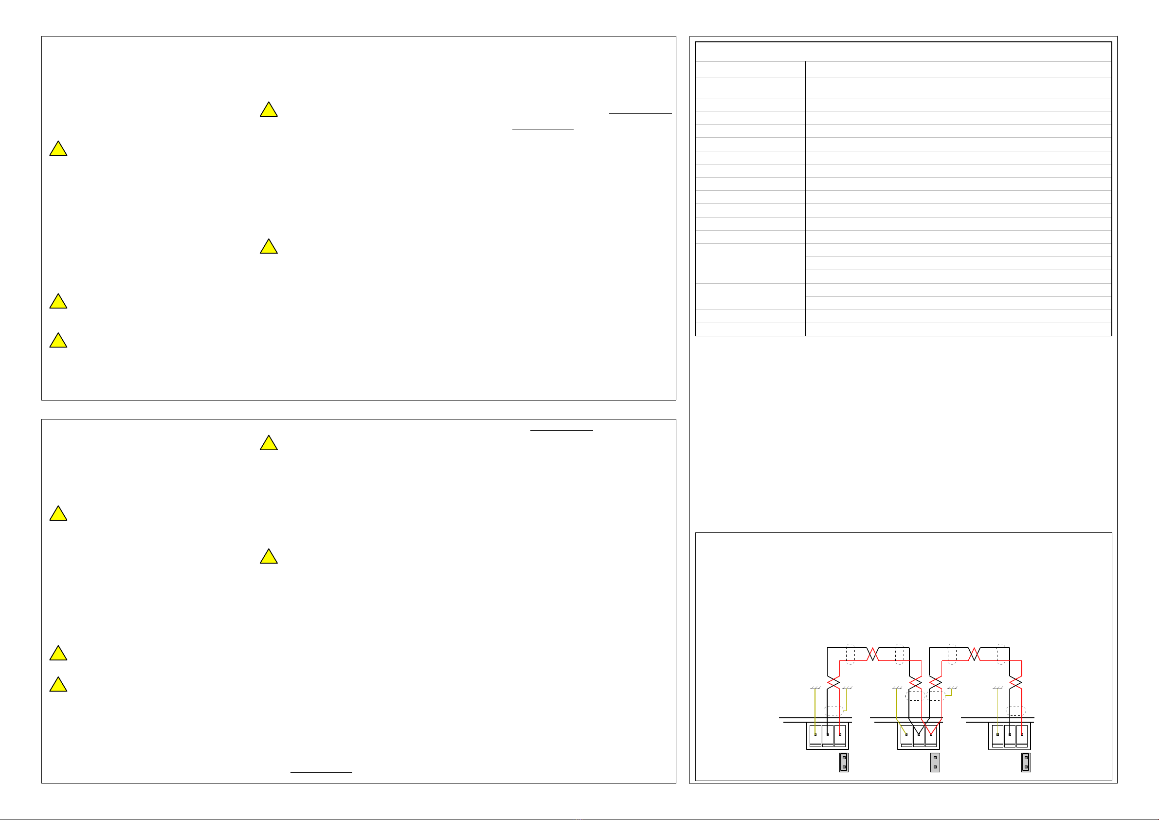
Collegamento Half-Duplex
•La distanza massima tra il primo e l’ultimo dei
dispositivi non deve superare i 1200 mt.
•La resistenza di terminazione deve essere sempre
inserita sul primo e sull’ultimo dei dispositivi.
•Il cavo deve essere schermato e twistato.
Half-Duplex connection
•The maximum distance between the first and the last
device does not exceed 4000 feet.
•The termination resistor must be always connected
on the first and on the last device.
•The cable must be shielded and twisted paired.
Schema di connessione
Drawing connection
Collegamento Bus di campo
Field bus connection
!
!
!
!
!
!
!
!
!
13
LK9
1313 P12P12
LK9
P12
LK9
P12
!


