Hoffmann MORSO NM User manual

© Hoffmann Machine Company, Inc.
OPERATING MANUAL
for
MORSO manual notching machine
Model NM
Hoffmann Machine Company, Inc.
1386 Drexel Road Valdese, NC 28690 USA
Phone: (828) 430 - 4510 Fax: (828) 430 –4620
e-mail: info@Hoffmann-USA.com
www.Hoffmann-USA.com
Toll-free Technical Support: (866) 248 –0100

Instruction Manual
MORSØ Notch Cutting Machine
Model NM
Contents
Introduction page A-1
Survey page B-1
Work Piece
Cutting of work piece on a
circular saw before notching page C-1
Functional Description:
General Description page D-1
Machine Description page D-2
Technical Data page E-1
Assembly Instructions:
General page F-1
Fitting of Table E tensions
and fences page F-1
Operating Instructions:
Before operating page G-1
Adjustment of Cock-bead Stops page G-2
Adjustment of Centre Stop page G-3
Adjustment of Flip Stops page G-4
Service eferences:
Lubrication Instructions page H-1
Cleaning page H-1
Changing of Knives and
Chip Breakers – Adjustment page H-2
Grinding of Knives page H-3
Changing of Spare Parts page H-4
ectifying Faults
Methods for Repair page I-1
Safety:
Safety Devices page J-1
Regulations page J-1
Spare Part Lists
page K-1 -
page K-7
1
Contents 0-1
Authorized U.S. Importer and Service Center:
Hoffmann Machine Company, Inc.
1386 Drexel oad
Valdese, N.C. 28690
Toll-free: 1 - 866 – 248 – 0100
www.Hoffmann-USA.com

Instruction Manual
MORSØ Notch Cutting Machine
Model NM
2
Introduction A-1
We recommend that you read this instruction manual thoroughly before using this machine.
Damage or faults on the machine caused by misuse or incorrect operation are not covered under our
conditions of warranty.
Use of the Instruction Manual:
The reference system of this Instruction Manual described below will help you to quickly find the
information you require (Picture A-1)
(1) Subject Heading
.
(2) Page Index
The letter (A) refers to the description of the section.
The number (1) refers to the page number of that section.
(3) Text
Description of the subject heading.
Illustration
A three dimensional, numbered drawing of the te t subject. The numbers in the te t korrespond to the
number in the drawing.

Instruction Manual
MORSØ Notch Cutting Machine
Model NM
3
Survey B-1
Survey
Pos. Designation Pos. Designation
1Frame 10 Sliding Stop
2Slide frame 11 Foot Pedal, complete
3Cross 12 Springs (not shown)
4Knife block 13 Table E tensions
5Side Knives 14 Safety Guard
6Nose Knives 15 Centre Stop
7Machine Table 16 Handle
8Fence 17 Chip Breaker (not shown)
9Cock-Bead stop

Instruction Manual
MORSØ Notch Cutting Machine
Model NM
4
Work Piece C-1
Cutting of work piece on a circular saw efore notching
Before the notching of the work piece it must be cut to the correct length on a circular saw.
It is very important that the saw blade is e actly adjusted to 90° to the machine table (see fig. 1). The
blade must also be e actly adjusted to 90° to the fence (see fig. 2).
Discrepancies arising from these cuts will result in gaps in the finished joints.
Fig. 1
Fig. 2

Instruction Manual
MORSØ Notch Cutting Machine
Model NM
5
Functional Description D-1
General Description
MO SØ NM notch cutter is the optimum machine to cut window bars, mullions, and cabinet face-
frames requiring haunch joints.
MO SØ NM is a manual foot-operated machine. The operation is easy.
MO SØ-NM notch cutting machine is provided with 2 sliding longitudinal stops, fi ed fences on both
the right and left side of the machine, nose knife, side knives, chip-breaker, cock-bead stops, centre
stop, and safety guard.
With the MO SØ NM you achieve a smooth, clean, and e act cut by notching the work piece in two
cuts.
This is done manually on the MO SØ-NM.
The forward movement of the knife block is infinitely adjustable.
A special lever system makes the operation of the machine very easy. Twin return springs bring the
knife block back to its home position.
The work pieces can be joined without any further finishing.

Instruction Manual
MORSØ Notch Cutting Machine
Model NM
6
Functional Description D-2
Picture
Picture D-2-1
Machine Description
The MO SØ-NM is constructed as a compact machine with a sturdy frame (1) with foot pedal (11).
The cutting assembly is situated at the top of the machine.
In the slide frame (2) fitted at the cross (3) the knife block (4) is moved up and down. The cross (3)
runs in the guidings of the table.
The knives (5) and nose knife (6) fitted on the knife block cut not only the notch but also cope the
corners to complete the joint.
The forward movement of the knife block is made manually.
The mullion is placed on the table (7) against the fences (8).
The cock-bead stops (9) are adjusted to the required cutting depth of the notch.
The adjustment of the sliding longitudinal stops (10) is done by means of a template of the stile.

Instruction Manual
MORSØ Notch Cutting Machine
Model NM
7
Technical Data
Technical Data
Machine Dimensions (max.): Working Capacity:
Length (a) 1600 mm (63”) Nose Knife Capacity 1.25 – 2,5 cm (½” -1”)
Width (b) 630 mm (25”)
Height (c) 840 mm (33”) Moulding width, ma 115 mm (4.5”)
Weight 50 kg (110 lb) Moulding Thickness, ma . 85 mm (3.3”)
Siting Considerations E tensions Table, left and right 478 mm (19”)
Distance to Wall min.1000 mm (40”) Fences, left and right 00 mm (31.5”)
Noise/Pollution:
Noise Level silent
Pollution nil/no dust
Technical Data E-1
c
a
b

Instruction Manual
MORSØ Notch Cutting Machine
Model NM
8
In General
F-1
Assembly Instructions F-1

Instruction Manual
MORSØ Notch Cutting Machine
Model NM
9
In General
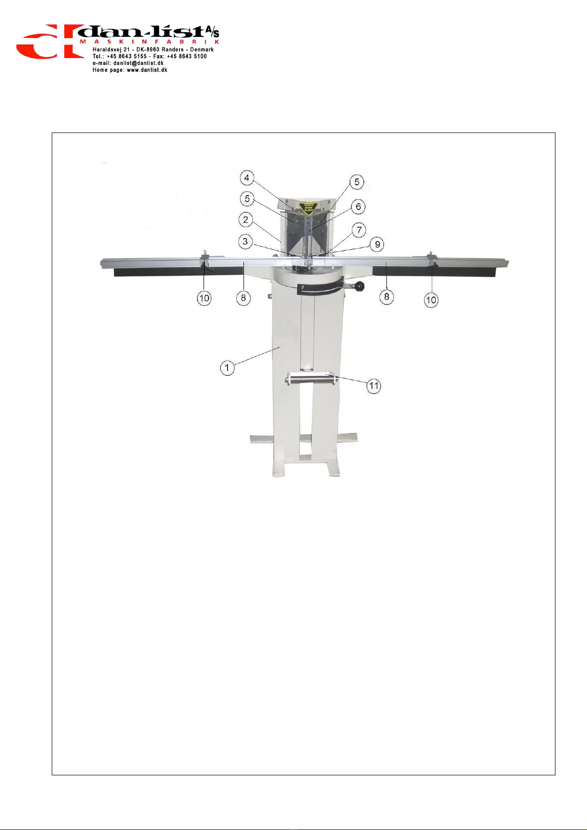
The machine is delivered ready for use and complete with standard equipment.
Only the table e tensions (13) and fences (8) are dismounted during transport.
Place the machine 1 m from the wall as stated in E-1. The machine can be fastened to the floor
using parabolts through the two holes in the bottom of the machine frame.
Check each time before starting that all protection devices are correctly fitted.
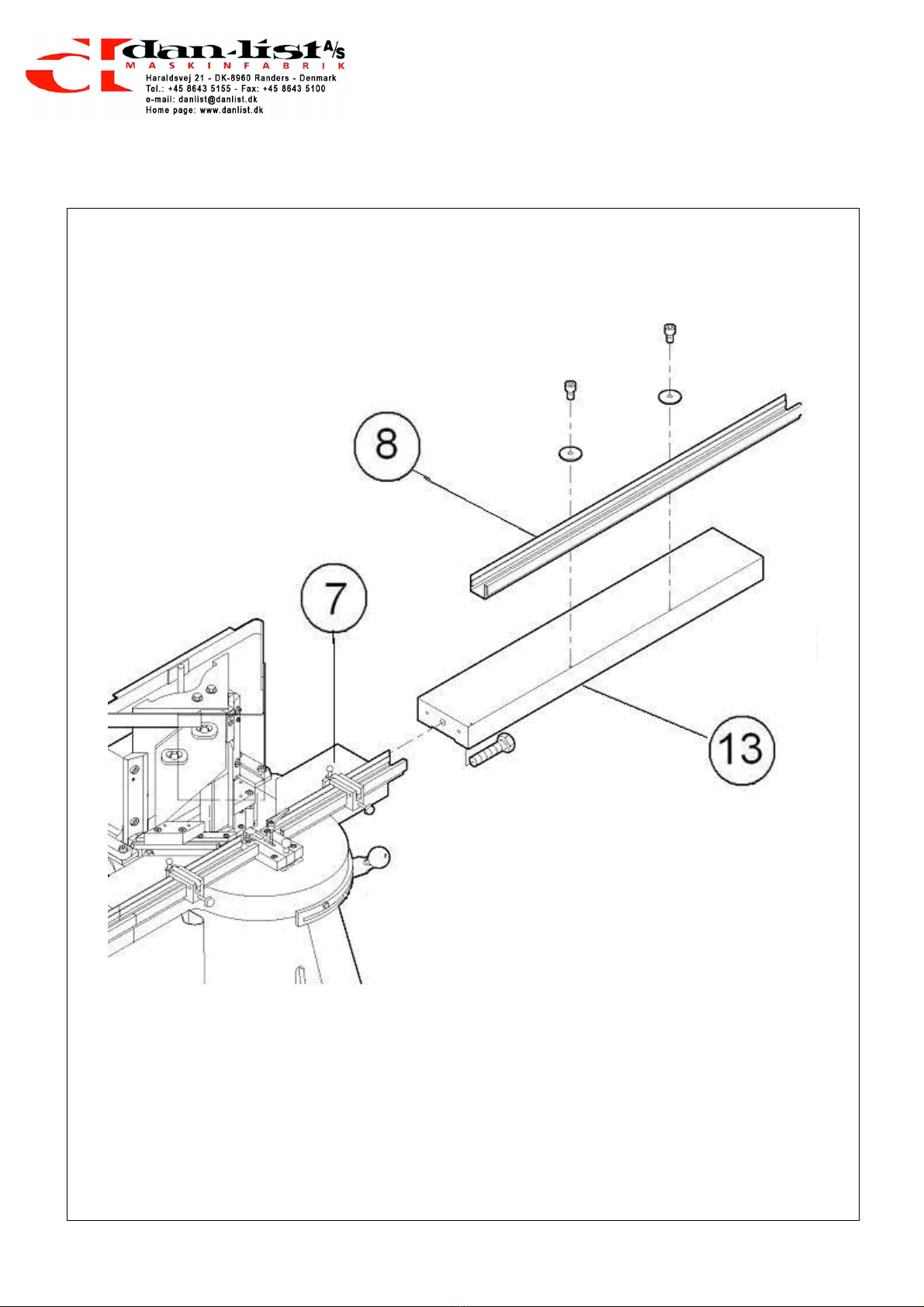
Fitting of the Ta le Extension and fences
(the drawing shows the right side, the same procedure is used on the left side).
Before fitting, the ends of the table e tension (13) and the table (7) must be cleaned thoroughly.
Special attention must be paid to the pin and screw holes, as the smallest amount of dirt will prevent
the correct alignment.
After cleaning, the table e tension (13) is pressed against the table so that the pins placed in the
table e tension are inserted in the pin holes in the table. The included bolt is now inserted into the
hole and fastened with a standard spanner.
The fence (8) is fitted on the table e tension (location pins are fitted in the table e tension). It is
secured with Allen screws.
Assembly Instructions F-1

Instruction Manual
MORSØ Notch Cutting Machine
Model NM
10
Before Operating
G-1
Operating Instructions G-1

Instruction Manual
MORSØ Notch Cutting Machine
Model NM
11
Before Operating
Before starting the machine the following must be checked and adjusted:
1. Check
1
a) knives (5 + 6)
general condition
sharpness
b) waste
room for waste
c) safety devices
fitting of all safety devices:
safety guard for knives (14)
d) table and table e tension
cleanness and undamaged surface
2. Adjustments
a) Cock-bead stops (9)
(adjustment instructions page G-2)
b) centre stop (15)
(adjustment instructions page G-3)
c) Sliding stops (10)
(adjustment instructions page G-4)
Operating Instructions G-1

Instruction Manual
MORSØ Notch Cutting Machine
Model NM
12
Cock- ead stops
Adjustment of the cock- ead stops (9)
The cock-bead stops (9) are adjusted as follows:
1. Loosen the Allen screws on the cock-bead stops (9) and move these to rear of the sliding guide.
2. Using a test piece (a) make a notch cut into the cock-bead. This cut must be the same depth as
the cock-bead. The overall width must be equal to the width of the centre cross-rail. When you
are satisfied the two sizes are equal, we can now position and lock the cock-bead stops (9).
3. Press the foot-pedal down and hold it in this position. By operating the hand lever, bring the knife
block (4) forward into the previously cut notch. Position the cock-bead stops (9) against the cock-
bead and lock them in place using the Allen screws. When these stops are fi ed in position the
knife block (4) can only cut into the cock-bead as far as this setting. The notch cut depth is then
referenced from the face of the cock-bead. The width of stile can vary without changing this
setting.
4. Check the alignment of the two cock-bead stops (9) using a straight edge. By bringing the knife
block (4) forward, check that they are level and true with the fence.
5. Lock the second Allen screws on the cock-bead stops (9).
6. This setting will allow you to make regularly accurate notch cuts in the stiles. These stops will
need no further adjustment unless the size of the cock-bead changes.
.
Operating Instructions G-2

Instruction Manual
MORSØ Notch Cutting Machine
Model NM
13
Adjustment of the centre stop (15)
The centre stop (15) regulates the amount of material cut from the corners of the cross-rails.
The centre stop is adjusted as follows:
1. The adjustment screws are located in each side of the Teflon head on the centre stop. They can
be turned in or out, to allow more or less material to be cut from the corner of the cross-rail.
The adjustment screws are adjusted e actly equal on both sides so that the distance from the
screw head to the centre of the Teflon piece is equal.
xample:
Nose width 12 mm:
The width of the Teflon piece is measured. The screws are adjusted e actly equal on both sides,
so that the distance from the screw head to the centre of the Teflon piece is 6 mm.
2. You can make minor adjustments if the width of the cross rail should vary (e.g. 11.9 or 12.2 mm
instead of 12 mm). Make a 45° cut in a test piece on the cross-rail and offer it up to the notch cut
already made in the test stile (see page G-2). If there is a gap in either of the two corners,
adjustments can be made on the screws until an e act and tight joint is achieved.
3. To achieve this balance, take a test piece of centre-rail and cut one corner. Turn the centre-rail to
the opposite side of the knife block up-side-down so that you cut in the same corner. Place it
against the centre stop and bring the cutting block partially through. If this causes a fine cut or the
knives do not touch the centre-rail, the two screws are not balanced with each other. The
adjustment screws are balanced until the cut is correct.
It is particularly important to get this balance, when frames are made with single cock-beads on
top and bottom rails. If the two corners are not taken off e actly equal, there will be a gap on one
corner and an over-tight joint on the other. This will also produce frames that are not square.
Operating Instructions G-3

Instruction Manual
MORSØ Notch Cutting Machine
Model NM
14
Flip stops
G-4-1
G-4-2
Operating Instructions G-4

Instruction Manual
MORSØ Notch Cutting Machine
Model NM
15
Adjustment of the flip-stops (10)
Making a Template
For setting the flip stop positions a template of the stile (upright section) is made. Mark the centre of
the positions on the cross-rails, incl. the top and bottom rails (see G-4-2) on the stile.
1. To make the template, put the stile in the machine. For the top and bottom rails always start
cutting from the end of the stile. Feed the section in by 5 mm at each cut (to prevent break out
along the end grain). See fig. G-4-1.
2. When a few cuts have been made, align the rail with the set mark and the centre line on the nose
knife (see fig. G-4-2). Make a proper cut in the position.
3. Bring the first stop forward against the end of the template and lock it.
4. Flip this stop over and go to the ne t position marked on the rail. Make the second cut and bring
the second stop to the same end of the rail. Lock the stop in position. Continue the procedure
until all stops have been positioned and set.
5. When setting the last stop, make a few 5 mm cuts from the end and in (see fig. G-4-1) (to prevent
break out) before setting the stop and locking it.
6. The same template is used to position the stops on the other side. Place the template on the
other side of the knife block up-side-down when setting the stops. Bring the cutting block into the
e isting notch cut outs and position each stop in turn – as described above.
Operating Instructions G-4

Instruction Manual
MORSØ Notch Cutting Machine
Model NM
16
Lu rication
H-1
Service H-1

Instruction Manual
MORSØ Notch Cutting Machine
Model NM
17
Lu rication Instructions
Appro . every two weeks lubricate the following:
The guides for
1. Knife block (4)
2. Slide Frame (2)
3. Cross (3) (lubricates simultaneously the forward movement of the knife block).
4. Links for the draw bar (15) of the knife block.
5. All links in the lever system (2), incl. spring suspension.
Lubricant: Any acid-free oil.
Cleaning
MO SØ-NM must be cleaned thoroughly after use.
Remove any waste wood from all the guides.
Remove the waste wood from behind the machine.
Resin from the mouldings can sometimes cause the knife blades to drag on the upward action of the
knife block. To remove this resin, use WD 40, sprayed onto a cloth made in the shape of a ball (so
that your fingers never go near the knives). Wipe in a downward action only so that neither the cloth
nor your fingers can come into contact with the cutting edge of the knives
Service H-1

Instruction Manual
MORSØ Notch Cutting Machine
Model NM
18
Changing Knives and Chip Breakers
H-2-1
H-2-2
Service H-2
Chip Breaker

Instruction Manual
MORSØ Notch Cutting Machine
Model NM
19
Changing of Knives and Chip Breaker – Adjustment
1. Knife Block (4) is placed in top position
2. The side knives (7) are dismounted by loosening bolts (a). The nose knife (6) is dismounted by
loosening screws (b).
TAKE CA E OF YOU FINGE S.
3. Clean the surfaces of the knife block and the new side knives (6) very carefully as even the
smallest impurity between side knife and knife block can cause an incorrect cut.
4. The nose knife (7) which fits the width of the cock-bead of the rail is fitted by means of the screws
(b) on the front of the knife block. Always tighten the top screw first.
5. The chip-breaker (17) is placed in the angle where the bottom knives meet. The width of the chip-
breaker must be the same as the width of the nose knife (c = d).
NOTE: When changing the chip-breaker (17) the knives must be dismounted.
6. Both side knives (5) are fitted with the bolts (a) on the knife block (4). These bolts must
not yet be tightened.
7. The side knives (5) must meet precisely with the nose knife (6) and neither front edge
must be further ahead (they must balance with the corners of the nose knife).
8. The bolts (a) can now be fastened.
9. Check the length of travel on the knife block (4), when operating the foot pedal. The
nose knife (6) must cut through the chip-breaker (17) by only 1-2 mm.
Service H-2
Table of contents
Other Hoffmann Industrial Equipment manuals

Hoffmann
Hoffmann MORSO NFXL User manual

Hoffmann
Hoffmann FX Series User manual

Hoffmann
Hoffmann X-10 User manual

Hoffmann
Hoffmann MU2 User manual

Hoffmann
Hoffmann eXess User manual

Hoffmann
Hoffmann GARANT VG Basic User manual

Hoffmann
Hoffmann Garant User manual

Hoffmann
Hoffmann GARANT HiPo Clamp 125 User manual

Hoffmann
Hoffmann 10585 User manual
Popular Industrial Equipment manuals by other brands

Master
Master MB Bucker 500 Instructions for use and maintenance

SICK
SICK SKS36S operating manual

Pfannenberg
Pfannenberg PWS 6152 Series operating manual

Master
Master MB Bucker 500 Instructions for use and maintenance

Siemens
Siemens Simatic S7-1500/ET 200MP Compact operating instructions

Tecnosystemi
Tecnosystemi Toolsplit HTS user manual