elsner elektronik KNX CP TP User manual

21.05.2021
Reservado el derecho a realizar modificaciones técnicas y a errores. / Technical changes and errors excepted.
Elsner Elektronik GmbH • Sohlengrund 16 • 75395 Ostelsheim • Alemania • www.elsner-elektronik.de • Servicio: +49 (0) 7033 / 30945-250
ES
Acoplador de línea y de área KNX TP
Instrucciones de instalación
Instrucciones de seguridad y de uso
El manual del producto y el archivo del producto (aplicación ETS 5) se pueden descargar
en el menú «Servicio» del sitio web de Elsner Elektronik en www.elsner-elektronik.de.
La instalación, el control, la puesta en marcha y la eliminación de fallos pueden llevarse a
cabo únicamente por un electricista autorizado.
¡PRECAUCIÓN!
¡Tensión eléctrica!
En el interior del aparato hay componentes conductores de tensión no protegidos.
• Inspeccione el dispositivo en busca de daños antes de la instalación. Ponga en funcionamiento
sólo los dispositivos no dañados.
• Cumplir con las directrices, reglamentos y disposiciones aplicables a nivel local para la instalación
eléctrica.
• Ponga inmediatamente fuera de funcionamiento el dispositivo o la instalación y protéjalo contra
una conexión involuntaria si ya no está garantizado el funcionamiento seguro.
Utilice el dispositivo exclusivamente para la automatización de edificios y respete las instrucciones
de uso. El uso inadecuado, las modificaciones en el aparato o la inobservancia de las instrucciones
de uso invalidan cualquier derecho de garantía.
Utilizar el dispositivo sólo como instalación fija, es decir, sólo cuando está montado y tras haber
finalizado todas las labores de instalación y puesta en marcha y sólo en el entorno previsto para
ello.
Elsner Elektronik no se hace responsable de las modificaciones de las normas posteriores a la pu-
blicación de este manual.
Descripción
El acoplador de líneas KNX TP KNX CP TP conecta dos líneas de par trenzado TP como línea
principal y línea secundaria. El KNX CP TP se puede utilizar como acoplador de líneas, acoplador
de áreas o repetidor (sin filtrado).
El KNX CP TP puede filtrar los telegramas que se van a redireccionar según la topología y el grupo
al que están dirigidos. Se admiten telegramas largos de hasta 240 bytes APDU. La configuración a
través de la línea secundaria se puede desactivar. Hay opciones especiales disponibles para el re-
direccionamiento de telegramas. La función de filtrado se puede desactivar brevemente con el bo-
tón de función, por ejemplo, durante la puesta en servicio. El KNX CP TP regresa automáticamen-
te al modo de funcionamiento normal cuando ha finalizado el intervalo de tiempo predefinido.
El dispositivo se alimenta a través de la línea principal. Los LED indican los estados de funciona-
miento y de filtro, los fallos de funcionamiento y los fallos de comunicación. Las líneas están sepa-
radas de forma galvánica.
Volumen de suministro
• Acoplador de línea
• 2 conectores KNX
Botones e indicadores LED
Estado del bus KNX TP (línea sec.) verde La línea secundaria funciona correctamente
Tráfico de telegramas KNX TP (línea
princ.)
verde (inter-
mitente)
Tráfico de telegramas
Tráfico de telegramas KNX TP (línea
princ.)
rojo (inter-
mitente)
Fallo de transmisión
Tráfico de telegramas KNX TP (línea
secundaria)
verde (inter-
mitente)
Tráfico de telegramas
Tráfico de telegramas KNX TP (línea
secundaria)
rojo (inter-
mitente)
Fallo de transmisión
Direcciones de grupo filtro verde Filtro activo
Direcciones de grupo filtro naranja Enviar todas
Direcciones de grupo filtro rojo Bloquear todas
KNX CP TP
70148
Fig. 1
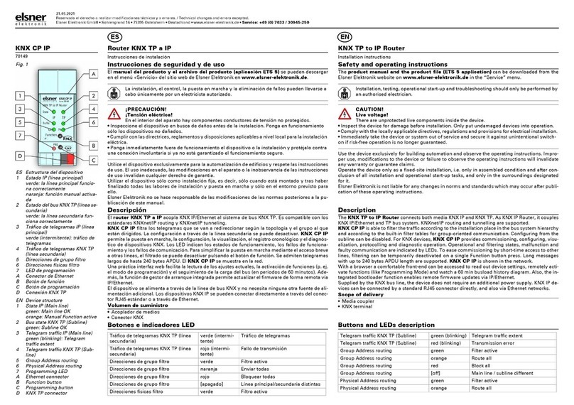
ES Estructura del dispositivo
1 Estado del bus KNX TP (línea
principal)
verde: la línea principal funcio-
na correctamente
naranja: función manual activa-
da
2 Estado del bus KNX TP (línea se-
cundaria)
3 Tráfico de telegramas KNX TP
(línea princ.)
4 Tráfico de telegramas KNX TP
(línea sec.)
5 Direcciones de grupo filtro
6 Direcciones físicas filtro
7 LED de programación
A Botón de función
B Botón de programación
C Conexión de la línea principal
KNX TP
D Conexión de la línea secundaria
KNX TP
EN Device structure
1 Bus state KNX TP (Main line)
green: Main line OK
orange: Manual Function active
2 Bus state KNX TP (Subline)
3 Telegram traffic KNX TP (Main
line)
4 Telegram traffic KNX TP (Sub-
line)
5 Group Address routing
6 Physical Address routing
7 Programming LED
A Function button
B Programming button
C KNX TP main line connector
D KNX TP subline connector
KNX TP Area and Line Coupler
Installation instructions
Safety and operating instructions
The product manual and the product file (ETS 5 application) can be downloaded from the
Elsner Elektronik website on www.elsner-elektronik.de in the “Service” menu.
Installation, testing, operational start-up and troubleshooting should only be performed by
an authorised electrician.
CAUTION!
Live voltage!
There are unprotected live components inside the device.
• Inspect the device for damage before installation. Only put undamaged devices into operation.
• Comply with the locally applicable directives, regulations and provisions for electrical installation.
• Immediately take the device or system out of service and secure it against unintentional switch-
on if risk-free operation is no longer guaranteed.
Use the device exclusively for building automation and observe the operating instructions. Impro-
per use, modifications to the device or failure to observe the operating instructions will invalidate
any warranty or guarantee claims.
Operate the device only as a fixed-site installation, i.e. only in assembled condition and after con-
clusion of all installation and operational start-up tasks, and only in the surroundings designated
for it.
Elsner Elektronik is not liable for any changes in norms and standards which may occur after publi-
cation of these operating instructions.
Description
The KNX TP line coupler KNX CP TP connects two TP lines as main line and subline. KNX CP
TP can be used as KNX line coupler and KNX area coupler or KNX repeater (without filtering).
KNX CP TP is able to filter the traffic according to the installation place in the bus system hierarchy
and according to the built-in filter tables for group-oriented communication. Long messages with
up to 240 bytes APDU are supported. Configuring from subline can be deactivated. Special functi-
ons for transmission of telegrams are available. Filtering can be temporarily deactivated on pres-
sing the Function button (Manual Function), i.e. to ease commissioning. KNX CP TP then switches
back to normal operation after expiry of a configurable time period.
The device is supplied with power by the main line. Operational and filtering states, malfunction
and faulty communication are indicated by LEDs. Lines have a galvanic separation between each
other.
Scope of delivery
• Line Coupler
• 2x KNX terminal
Buttons and LEDs description
Bus state KNX TP (Subline) green Subline OK
Telegram traffic KNX TP (Main line) green (blinking) Telegram traffic extent
Telegram traffic KNX TP (Main line) red (blinking) Transmission error
Telegram traffic KNX TP (Subline) green (blinking) Telegram traffic extent
Telegram traffic KNX TP (Subline) red (blinking) Transmission error
Group Address routing green Filter active
Group Address routing orange Route all
Group Address routing red Block all
Group Address routing [off] Main line / subline different
Physical Address routing green Filter active
Physical Address routing orange Route all
EN

21.05.2021
Reservado el derecho a realizar modificaciones técnicas y a errores. / Technical changes and errors excepted.
Elsner Elektronik GmbH • Sohlengrund 16 • 75395 Ostelsheim • Alemania • www.elsner-elektronik.de • Servicio: +49 (0) 7033 / 30945-250
Suministro: Power input:
21…30 V SELV Tensión de entrada Power supply
< 10 mA Consumo eléctrico Current consumption
Carcasa: Housing:
RAL 9018 Carcasa de plástico PA66, de color blanco Plastic PA66 housing, Housing colour white
90 mm × 36 mm × 71 mm Dimensiones (ancho × alto × profundidad), 2 módulos de 18 mm cada uno Dimensions (H × W × D), 2 modules at 18 mm
(TH35) Montaje (IEC60715) en carril de 35 mm (DIN) Mounting (IEC60715) 35 mm top-hat rail
Ø 0.6...0.8 mm
Conexiones de bus KNX conector KNX (rojo/negro) para línea principal y línea secundaria KNX TP,
sin tornillos, para cables de un solo hilo
KNX bus connections KNX connector (red/black) for KNX TP main line & subline,
screwless, for single-core cable
62 g Peso Weight
Condiciones ambientales: Environmental conditions:
-5…+45 °C Temperatura de trabajo Operating temperature
-20…+60 °C Temperatura de almacenamiento Storage temperature
5...93 % Humedad ambiente (sin condensación) Ambient humidity (non-condensing)
Seguridad eléctrica: Electrical safety:
2 Grado de contaminación (IEC60664) Pollution degree (IEC60664)
III Clase de protección (IEC61140) Protection class (IEC61140)
III Categoría de sobretensión (IEC60664) Overvoltage category (IEC60664)
Fig. 2
ES Esquema de conexión
EN Wiring diagram
Instalación
Lugar de montaje y preparación
• Instale el dispositivo exclusivamente en entornos secos. Protéjalo para que no se humedezca, se
ensucie o se dañe.
• Asegúrese de que se pueda acceder siempre al dispositivo para su utilización e inspección
• No abra la carcasa del dispositivo
• Utilice una herramienta adecuada para el montaje de conformidad con IEC60715
• y en un carril DIN adecuado (TS35). Cubra por completo las piezas conductoras de corriente de
manera que no sea posible retirar la cubierta sin utilizar una herramienta. El armario de distribu-
ción ha de garantizar una protección de contacto completa
Conexión
¡PELIGRO!
¡Tensión eléctrica!
El dispositivo se alimenta a través del bus KNX y no necesita ninguna otra fuente de
alimentación adicional.
• No lo conecte a una red de 230 V.
Conecte la línea de bus KNX, igual que en todas las conexiones KNX normales, con un cable de bus
KNX desnudo y un conector KNX TP. No dañe los aislamientos eléctricos al conectar los compo-
nentes
Mantenimiento
Este dispositivo no necesita mantenimiento. En caso necesario, límpielo con un trapo seco
Eliminación
Tras el uso, el aparato deberá eliminarse conforme a las disposiciones vigentes. ¡No lo deposite en
la basura doméstica!
Datos técnicos
Este producto cumple con las normas de las directivas europeas.
Direcciones de grupo filtro [apagado] Línea principal/secundaria distintas
Direcciones físicas filtro verde Filtro activo
Direcciones físicas filtro naranja Enviar todas
Direcciones físicas filtro rojo Bloquear todas
Direcciones físicas filtro [apagado] Línea principal/secundaria distintas
LED de programación rojo Modo de programación activado
Installation
Installation location and preparation
• Installation only in dry locations. Protect the device from moisture, dirt and damage
• Accessibility of the device for operation and visual inspection must be provided
• The housing of the device must not be opened
• For mounting use an appropriate equipment according to IEC60715
• Installation only on a 35 mm DIN rail (TH35). Terminals and metal parts under current must be
completely covered. It must be not possible to remove the cover without aid of a tool. Contact pro-
tection must be provided through the control cabinet
Connection
CAUTION!
Live voltage!
The device is supplied by the KNX bus and does not require any additional external power
supply.
• Do not connect to 230 V.
Connect the KNX bus line as for common KNX bus connections with a KNX bus cable, to be stripped
and plugged into the KNX TP connector. Do not damage electrical insulations when connecting
Maintenance
The device needs no maintenance. If necessary, the device can be cleaned with a dry cloth
Disposal
After use, the device must be disposed of in accordance with the legal regulations. Do not dispose
of it with the household waste!
Technical data
The product conforms to the conditions of the EU Directives.
Physical Address routing red Block all
Physical Address routing [off] Main line / subline different
Programming LED red Programming Mode active
This manual suits for next models
1
Other elsner elektronik Adapter manuals
Popular Adapter manuals by other brands
Belkin
Belkin Netbook Power Adapter user manual

NETGEAR
NETGEAR WG111U - Double 108 Mbps Wireless USB 2.0... user manual
Allied Telesis
Allied Telesis AT-2560FX 100 PCI installation manual

Enercell
Enercell Enercell 273-328 user manual
TRENDnet
TRENDnet TU2-HDMI Specifications
Asus
Asus Chromebit CS10 quick start guide
