Elster Instromet 2000 User manual

LV6.400
FIRMWARE LV6.400
Model 2000 iss 21
202/02-09
MODEL 2000 FLOW COMPUTER
INSTRUMENT INSTRUCTION MANUAL

Model 2000 issue 21 Page No 2
In the design and construction of this equipment and instructions contained in this manual,
due consideration has been given to safety requirements in respect of statutory industrial
regulations. Users are reminded that these regulations similarly apply to installation,
operation and maintenance, safety being mainly dependent upon the skill of the operator
and strict supervisory control.

Model 2000 issue 21 Page No 3

Model 2000 issue 21 Page No 4
CONTENTS Page No.
1. INTRODUCTION...........................................................................................................................................................1
2. GENERAL DESCRIPTION............................................................................................................................................2
2.1. MODEL 2000FLOW COMPUTER FACILITIES.......................................................................................................2
2.1.1. FLOW COMPUTER TYPES............................................................................................................................2
2.1.2. FLOW COMPUTER OPERATING MODES.....................................................................................................3
2.2. FRONT PANEL CONTROLS....................................................................................................................................5
2.2.1. KEY FUNCTIONS............................................................................................................................................5
2.2.1.1. MENU SCROLL UP AND DOWN KEYS.....................................................................................................5
2.2.1.2. RETURN or ENTER KEY............................................................................................................................5
2.2.1.3. INFORMATION KEY...................................................................................................................................5
2.2.1.4. FUNCTION KEYS.......................................................................................................................................5
2.2.1.5. EXPONENT KEY.........................................................................................................................................5
2.2.1.6. NUMERIC KEYS.........................................................................................................................................5
2.2.1.7. PRINTER KEY.............................................................................................................................................5
2.2.2. INDICATOR LEDS...........................................................................................................................................6
2.2.3. FRONT PANEL PROGRAMMING PORT........................................................................................................6
2.2.4. DISPLAY..........................................................................................................................................................7
2.2.5. MAIN MENU FUNCTIONS ..............................................................................................................................8
2.2.6. MAIN MENU FUNCTION Totals......................................................................................................................9
2.2.7. MAIN MENU FUNCTION Line Conditions.....................................................................................................10
2.2.8. MAIN MENU FUNCTION Coriolis Meter .......................................................................................................10
2.2.9. MAIN MENU FUNCTION Grab Sampler.......................................................................................................11
2.2.10. MAIN MENU FUNCTION Chromatograph ....................................................................................................11
2.2.11. MAIN MENU FUNCTION Station Controller..................................................................................................11
2.2.12. MAIN MENU FUNCTION PID Controller.......................................................................................................11
2.2.13. MAIN MENU FUNCTION Gas Data ..............................................................................................................12
2.2.14. MAIN MENU FUNCTION Liquid Data ...........................................................................................................12
2.2.15. MAIN MENU FUNCTION Settings ................................................................................................................13
2.2.16. MAIN MENU FUNCTION Preset Data ..........................................................................................................13
2.2.17. MAIN MENU FUNCTION Edit .......................................................................................................................14
2.2.18. MAIN MENU FUNCTION Output set-up........................................................................................................15
2.2.19. MAIN MENU FUNCTION Alarms ..................................................................................................................16
2.2.20. MAIN MENU FUNCTION Events ..................................................................................................................16
2.2.21. MAIN MENU FUNCTION Display..................................................................................................................16
2.2.22. MAIN MENU FUNCTION System .................................................................................................................16
2.2.23. MAIN MENU FUNCTION Calibration ............................................................................................................17
2.2.24. MAIN MENU FUNCTION Board Info.............................................................................................................18
2.2.25. MAIN MENU FUNCTION Information ...........................................................................................................18
2.2.26. MAIN MENU FUNCTION General Info..........................................................................................................18
2.3. MODEL 2000 FUNCTIONS.................................................................................................................................... 19
2.3.1. PRE-SET VALUE OF TOTAL FLOWS..........................................................................................................19
2.3.2. RESET OF TOTAL FLOWS TO ZERO..........................................................................................................19
2.3.3. CLOCK...........................................................................................................................................................19
2.3.4. MAINTENANCE MODE.................................................................................................................................19
2.3.5. PROVING MODE...........................................................................................................................................19
2.3.6. HOLD TOTALS..............................................................................................................................................19
2.3.7. ACTIVE DATA SNAPSHOT REPORT...........................................................................................................19
2.3.8. CO2 EMISSION CALCULATION...................................................................................................................20
2.3.9. AGA 8 FULL CCOMPOSITION .....................................................................................................................20
2.3.10. AGA 10 VoS CALCULATION ........................................................................................................................20
2.3.11. LUBRICATION MODULE ..............................................................................................................................20
2.4. INPUT SIGNALS ....................................................................................................................................................22
2.4.1. TURBINE METER..........................................................................................................................................22
2.4.1.1. MINIMUM INPUT FREQUENCY...............................................................................................................22
2.4.1.2. TURBINE METER LINEARISATION.........................................................................................................22
2.4.1.3. BI-DIRECTION METER OPERATION ......................................................................................................22
2.4.1.4. BLADE FAILURE DETECTION.................................................................................................................23
2.4.2. ULTRASONIC GAS METER..........................................................................................................................25
2.4.2.1. UNIFORM SOFTWARE ............................................................................................................................25
2.4.2.2. METER CORRECTION FOR TEMPERATURE AND PRESSURE...........................................................25

Model 2000 issue 21 Page No 5
2.4.2.3. METER LINEARISATION..........................................................................................................................26
2.4.2.4. METER ALARMS......................................................................................................................................26
2.4.2.4.1. ACCOUNTABLE METER ALARMS................................................................................................... 26
2.4.2.4.2. NON-ACCOUNTABLE METER ALARMS..........................................................................................26
2.4.3. ORIFICE PLATE & VENTURI TUBE MEASUREMENT................................................................................ 27
2.4.3.1. DIFFERENTIAL PRESSURE MEASUREMENT....................................................................................... 28
2.4.3.1.1. DIFFERENTIAL PRESSURE UNITS................................................................................................. 28
2.4.3.1.2. HART TRANSMITTER DIFFERENTIAL PRESSURE INPUTS..........................................................28
2.4.3.1.3. ANALOGUE TRANSMITTER DIFFERENTIAL PRESSURE INPUTS...............................................28
2.4.3.2. MASS FLOW MEASURMENT LINEARISATION...................................................................................... 28
2.4.3.3. WET GAS FLOW MEASUREMENT..........................................................................................................29
2.4.3.3.1. WET GAS FLOW MEASUREMENT 1................................................................................................ 29
2.4.3.3.2. WET GAS FLOW MEASUREMENT 2................................................................................................ 29
2.4.4. CORIOLIS METER........................................................................................................................................ 29
2.4.4.1. CORIOLIS METER PULSE OUTPUT.......................................................................................................29
2.4.4.2. CORIOLIS METER SERIAL OUTPUT......................................................................................................30
2.4.4.3. CORIOLIS METER CALCULATIONS....................................................................................................... 30
2.4.5. PRESSURE AND TEMPERATURE INPUTS................................................................................................ 32
2.4.5.1. PRESSURE UNITS...................................................................................................................................32
2.4.5.2. TEMPERATURE UNITS............................................................................................................................32
2.4.5.3. HART TRANSMITTER PRESSURE AND TEMPERATURE INPUTS......................................................32
2.4.5.4. ANALOGUE TRANSMITTER PRESSURE AND TEMPERATUREINPUTS............................................ 34
2.4.5.5. PRT TEMPERATURE INPUT ...................................................................................................................34
2.4.5.6. PRESSURE & TEMPERATURE SENSOR SCALING..............................................................................34
2.4.5.7. AVERAGE PRESSURE, TEMPERATURE & DENSITY........................................................................... 34
2.4.6. MULTIPLE TRANSMITTER INPUTS.............................................................................................................35
2.4.7. GAS DATA INPUT.........................................................................................................................................35
2.4.7.1. NORMAL OPERATION.............................................................................................................................36
2.4.7.2. ALARM OPERATION................................................................................................................................37
2.4.7.3. GAS CHROMATOGRAPH INPUT ............................................................................................................37
2.4.7.4. ANALOGUE TRANSMITTER INPUTS FOR GAS DATA..........................................................................37
2.4.7.5. HEATING VALUE UNITS.......................................................................................................................... 37
2.4.7.6. AVERAGE GAS DATA..............................................................................................................................38
2.4.8. DENSITY TRANSDUCER INPUTS...............................................................................................................38
2.4.8.1. MULTIPLE DENSITY TRANSDUCER INPUTS........................................................................................38
2.4.8.2. SOLARTRON DENSITY TRANSDUCER INPUTS ................................................................................... 39
2.4.8.3. SARASOTA DENSITY TRANSDUCER INPUTS......................................................................................41
2.4.9. RELATIVE DENSITY TRANSDUCER INPUT...............................................................................................41
2.4.10. SWITCH STATUS INPUTS ...........................................................................................................................42
2.4.11. STATION PRESSURE AND TEMPERATURE INPUTS................................................................................ 43
2.4.11.1. STATION PRESSURE UNITS.............................................................................................................. 43
2.4.11.2. STATION TEMPERATURE UNITS.......................................................................................................43
2.4.11.3. HART TRANSMITTER STATION PRESSURE AND TEMPERATURE INPUTS.................................43
2.4.11.4. ANALOGUE TRANSMITTER STATION PRESSURE AND TEMPERATURE INPUTS.......................44
2.4.11.5. STATION PRESSURE & TEMPERATURE SENSOR SCALING.........................................................44
2.4.12. SMART INDEX AND ENCODER INPUT.......................................................................................................44
2.4.13. ANALOGUE INPUT FOR GRAB SAMPLER CAN LEVEL INDICATION.......................................................44
2.5. OUTPUT SIGNALS................................................................................................................................................45
2.5.1. ANALOGUE OUTPUT SIGNALS...................................................................................................................45
2.5.2. PID CONTROL ANALOGUE OUTPUT SIGNALS......................................................................................... 45
2.5.3. SWITCHED OUTPUT SIGNALS ...................................................................................................................47
2.6. ALARMS, WARNINGSAND FAULTS....................................................................................................................47
2.6.1. ACCOUNTABLE ALARMS............................................................................................................................47
2.6.1.1. GENERAL ACCOUNTABLE ALARMS......................................................................................................47
2.6.1.2. TURBINE ACCOUNTABLE ALARMS.......................................................................................................48
2.6.1.3. ULTRASONIC ACCOUNTABLE ALARMS................................................................................................48
2.6.1.4. DIFFERENTIAL PRESSURE ACCOUNTABLE ALARMS ........................................................................48
2.6.1.5. DENSITY ACCOUNTABLE ALARMS.......................................................................................................48
2.6.1.6. STATION ACCOUNTABLE ALARMS.......................................................................................................49
2.6.1.7. SMART INDEX ACCOUNTABLE ALARMS.............................................................................................. 49
2.6.1.8. CORIOLIS METER ACCOUNTABLE ALARMS........................................................................................49
2.6.1.9. GRAB SAMPLER ACCOUNTABLE ALARMS .......................................................................................... 49
2.6.2. NON-ACCOUNTABLE ALARMS...................................................................................................................49

Model 2000 issue 21 Page No 6
2.6.2.1. GENERAL NON ACCOUNTABLE ALARMS.............................................................................................49
2.6.2.2. TURBINE NON ACCOUNTABLE ALARMS..............................................................................................50
2.6.2.3. ULTRASONIC NON ACCOUNTABLE ALARMS.......................................................................................50
2.6.2.4. DIFFERENTIAL PRESSURE NON ACCOUNTABLE ALARMS ...............................................................50
2.6.2.5. DENSITY ACCOUNTABLE ALARMS.......................................................................................................50
2.6.2.6. SMART INDEX NON ACCOUNTABLE ALARMS..................................................................................... 50
2.6.2.7. CORIOLIS METER NON ACCOUNTABLE ALARMS...............................................................................50
2.6.2.8. GRAB SAMPLER NON ACCOUNTABLE ALARMS.................................................................................50
2.6.4. FAULTS.........................................................................................................................................................51
2.6.5. WARNINGS...................................................................................................................................................51
2.6.6. HIGH AND LOW FLOW ALARMS.................................................................................................................51
2.6.7. CLEARING OF ALARMS...............................................................................................................................51
2.7. PULSED OUTPUTS FOR TOTAL FLOWS............................................................................................................52
2.8. PULSED OUTPUTSFOR CONTROL FUNCTIONS..............................................................................................54
2.8.1. FLOW DIRECTION OUTPUT........................................................................................................................54
2.8.2. FIXED OUTPUT.............................................................................................................................................54
2.8.3. DIGITAL INPUT STATUS OUTPUT.............................................................................................................. 54
2.8.4. VALVE CONTROL OUTPUT.........................................................................................................................54
2.8.5. FUNCTION OUTPUT.....................................................................................................................................54
2.8.6. GRAB SAMPLER OUTPUT SIGNALS..........................................................................................................54
2.8.6.1. GRAB SAMPLER OUTPUT OPERATION................................................................................................54
2.8.6.1.1. CONFIGURATION SETTINGS..........................................................................................................54
2.8.6.2. GRAB SAMPLER CALCULATIONS..........................................................................................................55
2.9. COMMUNICATIONS PORTS.................................................................................................................................56
2.10. INPUT 2 BOARD................................................................................................................................................57
2.11. NETWORK 2 COMMUNICATION BOARD........................................................................................................58
2.13. PRINTER FACILITY...........................................................................................................................................59
2.14. POWER SUPPLY +24V dc OPERATION..........................................................................................................59
3. INSTALLATION, INITIALISATION & CALIBRATION.................................................................................................. 60
3.1. MECHANICAL INSTALLATION..............................................................................................................................60
3.2. ELECTRICAL INSTALLATION...............................................................................................................................60
3.2.1. POWER SUPPLY..........................................................................................................................................60
3.2.2. TRANSMITTER INPUT CONNECTIONS......................................................................................................60
3.2.3. HART TRANSMITTER INPUT CONNECTIONS........................................................................................... 60
3.2.4. OUTPUT SIGNAL CONNECTIONS ..............................................................................................................60
3.3. INITIALISATION.....................................................................................................................................................60
3.3.1. INTERNAL SWITCHES.................................................................................................................................60
3.3.2. SETTING THE INTERNAL SWITCHES........................................................................................................ 60
3.3.3. OPERATION..................................................................................................................................................61
3.4. SOFTWARE INSTALLATION.................................................................................................................................61
3.5. CALIBRATION........................................................................................................................................................61
3.5.1. INPUT SIGNALS............................................................................................................................................61
3.5.1.1. DIGITAL INPUT SIGNALS........................................................................................................................61
3.5.1.2. HART INPUT SIGNALS ............................................................................................................................61
3.5.1.3. ANALOGUE INPUT SIGNALS..................................................................................................................62
3.5.2. OUTPUT SIGNALS........................................................................................................................................63
3.5.2.1. DIGITAL OUTPUT SIGNALS....................................................................................................................63
3.5.2.2. ANALOGUE OUTPUT SIGNALS..............................................................................................................63
4. MAINTENANCE...........................................................................................................................................................64
4.1. INITIAL CHECKS.................................................................................................................................................... 64
4.2. REPLACEMENT PARTS........................................................................................................................................64
4.3. INPUT BOARD LINK SETTINGS...........................................................................................................................65
4.4. INPUT 2 BOARD LINK SETTINGS........................................................................................................................65
4.5. INPUT 2 BOARD 4 WIRE PRT LINK SETTINGS...................................................................................................66
4.6. OUTPUT BOARD LINK SETTINGS.......................................................................................................................66
4.7. DISPLAY BOARD LINK SETTINGS....................................................................................................................... 67
4.8. PRT INPUT BOARD LINKSETTINGS...................................................................................................................67
4.9. COMMS BOARD LINK SETTINGS........................................................................................................................67
APPENDIX 1 Alarm Information...........................................................................................................................................68
APPENDIX 1a Alarm, Warning and Fault Codes..........................................................................................................68
APPENDIX 1b Parameter Symbols For Non-Accountable Alarms................................................................................68
APPENDIX 1c Parameter Symbols for Accountable Alarms.........................................................................................69
APPENDIX 1d Temperature Alarm...............................................................................................................................72

Model 2000 issue 21 Page No 7
APPENDIX 1e Fault Codes...........................................................................................................................................72
APPENDIX 1f Warning Codes......................................................................................................................................72
APPENDIX 2 Event Codes...................................................................................................................................................73
APPENDIX 3 Gas Chromatographs Supported................................................................................................................... 75
APPENDIX 3a Instromet Encal 2000,Daniels 2251, Daniels 2551 and ABB 8X00 Chromatographs.......................... 76
APPENDIX 3b Yamatake Model HGC303 Chromatograph.......................................................................................... 78
APPENDIX 3c Siemens Optichrome Chromatograph...................................................................................................79
APPENDIX 3d Rosemount GCX Chromatograph.........................................................................................................80
APPENDIX 3e Instromet Station Controller Type 793-7SC Chromatograph Emulation...............................................81
APPENDIX 3f Instromet Model 2000 and ENSonic Chromatograph Emulation...........................................................82
APPENDIX 3g ABB Model 3100 Chromatograph.........................................................................................................83
APPENDIX 3h Instromet ENCAL 3000 Chromatograph...............................................................................................84
APPENDIX 3i Siemens Maxum II Chromatograph.......................................................................................................86
APPENDIX 3j Daniels 2350 Chromatograph...............................................................................................................87
APPENDIX 4 External Connections..................................................................................................................................... 89
APPENDIX 5 Coriolis Communications...............................................................................................................................93
APPENDIX 6 Ultrasonic Meters...........................................................................................................................................94
APPENDIX 6a Instromet QSonic...................................................................................................................................94
APPENDIX 6b Daniels Senior Sonic.............................................................................................................................95
APPENDIX 6c FlowSIC 600..........................................................................................................................................96
APPENDIX 6d Panametrics GM 868.............................................................................................................................96
APPENDIX 6e Panametrics IGM 878............................................................................................................................97
APPENDIX 7 FIGURE LIST................................................................................................................................................. 99

Model 2000 Flow Computer Instruction Manual
1.0 INTRODUCTION
Model 2000 issue 21 Page No 1
1. INTRODUCTION
The INSTROMET Model 2000 Flow Computer is designed to calculate the total energy, volume and instantaneous flow rates
of gas and alternatively Liquids. Calculation is carried out using inputs from pulse generating turbine meters or from
ultrasonic gas meters or from differential pressure measurement across orifice plates together with temperature sensors and
transmitters for line pressure. The Model 2000 uses pre-set or active input values of relative density, gas composition data
and heating value, active values can be received directly from a gas chromatograph or can be written serially from a
supervisory system.
The flow of gas is calculated using gas compressibility (Z factor) methods selected from a list of which includes AGA 8, ISO
12213 and AGA 3 NX19 as well as fixed factors for certain applications. As an alternative the flow of gas can be calculated
using a transducer input for line density.
The flow of liquid is calculated using fixed or measured factors for density and relative density and correction based upon
measured temperature and pressure of the Liquid in accordance with API standard chapters 11.2.1M, 11.2.2M & 12.
The Model 2000 has the facility of both high and low alarms on all active input signals, the alarms can be selected to enable
a default value to be used in flow calculation for the parameter in the alarm condition. Indication is given of the time of
occurrence and clearance of the alarm state, alarm output signals are also provided.
A feature of the Model 2000 is that it can use digital communication to the differential pressure, pressure and temperature
transmitters using the HART protocol eliminating the need for calibration of the Model 2000. This feature also eliminates the
errors in flow measurement due to ambient temperature effects on the Model 2000, only the temperature coefficient of the
transmitters contribute to the error.
As an alternative the Model 2000 can be operated from transmitters that supply a 4–20mA current output and also direct
from a 100 ohm platinum resistance thermometer for temperature measurement, these types of input are measured using
analogue inputs and a high resolution A-D converter. The analogue inputs are calibrated using software.
The Model 2000 has two RS232/RS485 serial data outputs which can provide Modbus RTU or ASCII communication
protocol for operation with system devices and a serial ASCII protocol compatible with most printers.
To provide maximum security of operating data and flow measurement while maintaining flexibility with the auxiliary
functions, the Model 2000 is provided with an edit facility where selected data can be changed while security can be
preserved with critical data.
All input and output signals are tested to ensure that they are within the designed operating limits, an alarm display records
the time when alarms occur and clear. During an alarm condition the total flows can be selected to be displayed on separate
counters.

Model 2000 Flow Computer Instruction Manual
2.0 GENERAL DESCRIPTION
Model 2000 issue 21 Page No 2
2. GENERAL DESCRIPTION
The Model 2000 Flow Computer comprises a standard size half width 19 inch rack which contains plug-in printed circuit
boards connected to a mother board.
The Model 2000 front panel contains a liquid crystal display, keyboard, display buttons and indicator LED's. The liquid crystal
display (LCD) is a graphic dot matrix type which is used to display all of the data entered and flow information. Thekeyboard
is used to select the data to be entered into the Model 2000 memory and select all of the displayed information.
Input and output signals are connected to the Model 2000 by 9 pin D type connectors and plug in terminal blocks located at
the rear or the unit. The Model 2000 is operated from a 24Vdc. supply.
The front and rear panel arrangement are shown in figures 1and 2.
2.1. MODEL 2000 FLOW COMPUTER FACILITIES
2.1.1. FLOW COMPUTER TYPES
The Model 2000 Flow Computer can be configured into the following basic types of measurement device.
a) Turbine Gas 1 Stream, 2 Stream or 3 Stream. t1, t2, t3
Gas flow computer 1, 2 or 3 measurement streams using Turbine or pulse type meters as the primary
flow measurement device and Pressure, Temperature andCompressibility for flow correction.
b) Ultrasonic Gas 1 Stream. u1
Gas flow computer 1 measurement stream using an Instromet Ultrasonic meter as the primary flow
measurement device (Uniform communication to meter) and Pressure, Temperature and
Compressibility for flow correction.
Gas flow computer 1 measurement stream using an FlowSIC 600 ultrasonic meter, Panametrics
GM868 or Daniel Senior Sonic ultrasonic meter as the primary flow measurement device (Modbus
RTU communication to meter) and Pressure, Temperature and Compressibility for flow correction.
c) Ultrasonic Gas 2 Streams or 3 Streams. u2, u3
Gas flow computer 2 or 3 measurement streams using Instromet Ultrasonic meters as the primary
flow measurement devices (Modbus RTU multidrop communication to meter) and Pressure,
Temperature and Compressibility for flow correction.
Gas flow computer 2 or 3 measurement streams using an FlowSIC 600 ultrasonic meter,
Panametrics GM868 or Daniel Senior Sonic ultrasonic meter as the primary flow measurement
devices (Modbus RTU multidrop communication to meter) and Pressure, Temperature and
Compressibility for flow correction.
d) Orifice Gas 1 Stream or 2 Stream. o1
Gas flow computer 1 or 2 measurement streams using Orifice plate measurement as the primary flow
measurement device and Pressure, Temperature and Compressibility for flow correction.
e) Turbine DensityGas 1 Stream. td1
Gas flow computer 1 measurement stream using Turbine or pulse type meter as the primary flow
measurement device and Density measurement for flow correction.
f) Ultrasonic Density Gas 1 Stream. ud1
Gas flow computer 1 measurement stream using an Instromet Ultrasonic meter as the primary flow
measurement device and Density measurement for flow correction.
g) Orifice Density Gas 1 Stream. od1
Gas flow computer 1 measurement stream using Orifice plate measurement as the primary flow
measurement device and Density measurement for flow correction.
h) Turbine Liquid 1 Stream, 2 Stream or 3 Stream. lt1, lt2, lt3
Liquid flow computer 1, 2 or 3 measurement streams using Turbine or pulse type meters as the
primary flow measurement device andTemperature for flow correction.
i) Turbine Liquid Density 1 Stream. ltd1
Liquid flow computer 1 measurement stream using Turbine or pulse type meters as the primary flow
measurement device and Line Density for flow correction.
j) Ultrasonic Liquid 1 Stream. lu1
Liquid flow computer 1 measurement stream using an Instromet Ultrasonic meter as the primary flow
measurement device and Temperature for flow correction.
k) Venturi 1 Stream or 2 Stream. vt1, vt2
Steam flow computer 1 or 2 measurement streams using Venturi measurement as the primary flow
measurement device and Pressure, Temperature and Compressibility for flow correction. This flow
computer is for STEAM measurement only.

Model 2000 Flow Computer Instruction Manual
2.0 GENERAL DESCRIPTION
Model 2000 issue 21 Page No 3
l) Station Controller. stn
Device to calculate Station Flow values from up to 5 individual flow computers and to distribute gas
data information to those flow computers.
m) Wet Gas Venturi 1 Stream WGV1
Steam flow computer 1 measurement stream using Venturi measurement as the primary flow
measurement device and Pressure, Temperature and Compressibility for flow correction. This flow
computer is for Wet Gas measurement only.
n) Wet Gas Venturi type 2 flow line Stream WGV21
Flow line Steam flow computer measurement stream using Venturi measurement as the primary flow
measurement device Mass flow transmitter incorporating measurements for Differential Pressure,
Pressure, Temperature and Compressibility for flow correction. This flow computer is for Wet Gas
measurement only.
o) Liquid Coriolis Meter 1 Stream or 2 Stream. lc1, lc2
Liquid flow computer 1 or 2 measurement streams using Micro Motion type Coriolis Meter
measurement as the primary flow measurement device and Density measurement device. Optional
Pressure and Temperature measurement for flow correction.
The basic type selected must be configured into the M2000 using the set-up software, this will then determine the circuit
boards required and inputs and outputs to be configured.
The Model 2000 will calculate the volume of gas or liquids using pre-set or active gas data and active input signals for
pressure and temperature and either inputs from pulse generating turbine meters, a high frequency pulse input used for flow
calculation and a low (or reference) frequency input from the index or from an Instromet type Ultrasonic gas meter or from
the differential pressure measurement across an orifice plate. The function and correction of all types of available input is
described in section 2.3 of this manual.
The flows calculated are displayed on the LCD display as a 12 digit number (8 digits- decimal- 4 digits) with the scaling
factor, units and symbol.
e.g. +Vn1 = 12345678.1234 X 100 m3
The scaling factor (symbol twf) is entered via the keyboard. The Model 2000 can be selected to total the flow on a separate
counter when an alarm condition occurs.
2.1.2. FLOW COMPUTER OPERATING MODES
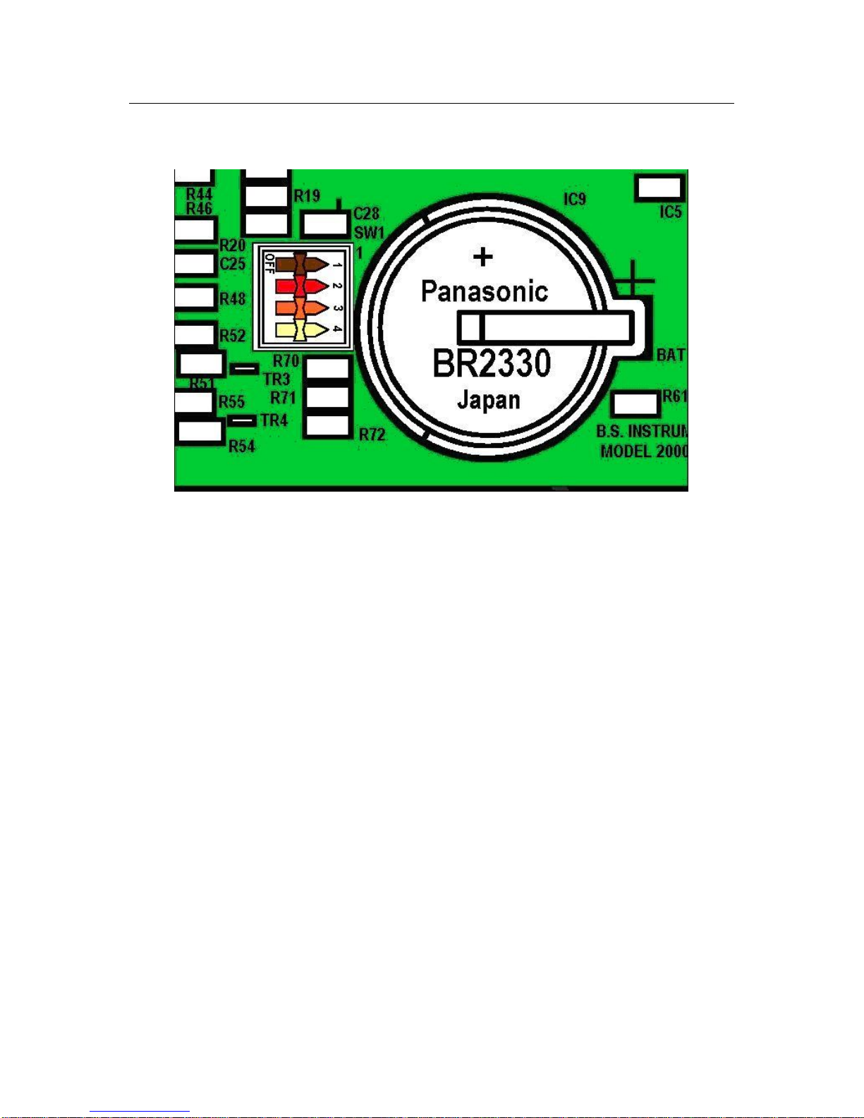
The security, set-up and operational modes of the Model 2000 is initiated by the setting of mode switches located under an
access hole on the side of the Model 2000 the access hole is normally covered by a plastic cover and can also be sealed
using a self adhesive security label (See figure 16 for details) .
The designationand function of the mode switches is as follows:-
Normal RUN mode:-
Switch No. ON OFF
1 Security 1 Off Security 1 On
2 Security 2 Off Security 2 On
3 Run Mode
4 Backup Battery On Backup Battery Off
Programming Boot mode:-
Switch No. ON OFF
1 Security 1 Off Security 1 On
2 Irda Infra Red or Front Panel USB
Connector Rear Connector Skt 1
3 Boot Mode
4 Backup Battery On Backup Battery Off
Model 2000 Flow Computer Instruction Manual
2.0 GENERAL DESCRIPTION
Model 2000 issue 21 Page No 4
View of Microprocessor Board Showing Mode Switches and Backup Battery
To place the Model 2000 in fully secure mode (i.e. no data can be altered either via communication or via the EDIT mode )
Mode switches 1 and 2 must be in the OFF position.
To place the Model 2000 in partial secure mode (i.e. selected data can be altered either via communication or via the EDIT
mode ) one of the security Mode switches must be OFF the other must be ON.
To place the Model 2000 in fully open mode (i.e. all data can be altered either via communication or via the EDIT mode )
Mode switches 1 and 2 must be in the ON position.
Mode switch 3 should only be set to the Boot (OFF) position if a new operating programme is going to be downloaded into
the machine. In all other modes of operation mode switch 3 must be placed in the run (ON) position.
Mode switch 4 enables the battery backup (ON/OFF) function for shipping, long term storage and transportation this should
be set to the OFF position, and should only be set to the ON position immediately prior to operation of the Model 2000.

Model 2000 Flow Computer Instruction Manual
2.0 GENERAL DESCRIPTION
Model 2000 issue 21 Page No 5
2.2. FRONT PANEL CONTROLS
All of the controls necessary to operate the Model 2000 are located on the front panel and provide the following functions:-
2.2.1. KEY FUNCTIONS
2.2.1.1. MENU SCROLL UPAND DOWN KEYS
SCROLL UP KEY Use to move the menu item highlight bar up to the required line of
data that is going to be selected.
SCROLL DOWN KEY Use to move the menu item highlight bar down to the required line of
data that is going to be selected.
2.2.1.2. RETURN or ENTER KEY
RETURN or ENTER The enter key allows the value of data to be entered or highlighted
item to be selected. It is generally used when an item of data is tobe
edited, selectedor confirmed.
2.2.1.3. INFORMATION KEY
INFORMATION KEY The information key can be used to provide additional screen helpor
information . Whenever the is shown in the display of the Model
2000 this key can be pressed and the additional information will be
shown as a helpor information box.
2.2.1.4. FUNCTION KEYS
FUNCTION KEYS The keys shown with the symbols [F1] , [F2] , [F3] & [F4] are the
function keys, these keys will have different operating functions
depending upon the particular page that is currently in use. The
particular function for each individual key is shown directly above
each key as a highlighted bar on the Model 2000 display. Note that
not function keys will operate on all pages, if a function key has no
function then there will be no function indicated above it.
2.2.1.5. EXPONENT KEY
EXPONENT The exponent key (future use) can be used to exponent type
numbers where allowable.
This key currently has no function.
2.2.1.6. NUMERIC KEYS
NUMERIC KEYS The keys shown with the symbols [1], [2], [3], [4], [5], [6], [7], [8], [9],
[0], [.] & [-] can used when entering or editing numeric values into
the memory of the model 2000.
2.2.1.7. PRINTER KEY
PRINTER The printer key is a shortcut key to the printer function menu, this
key will only function if a printer has been set up in the Model 2000
and is functioning correctly. The symbol ¬will appear on the
bottom left hand corner of the display if there are printer reports
available to be printed.

Model 2000 Flow Computer Instruction Manual
2.0 GENERAL DESCRIPTION
Model 2000 issue 21 Page No 6
2.2.2. INDICATOR LEDS
There are five indicator LED's on the Front panel of the Model 2000, from top to bottom these are as shown:-
Power ON GREEN
Accountable Alarm RED
Non-accountable Alarm RED
Fault RED
Low or High Flow Limit YELLOW
2.2.3. FRONT PANEL PROGRAMMING PORT
There are two types of Model 2000 Front Panel programming ports both have exactly the same function they differ in the
method of connection from a PC to the Model 2000.
On earlier models of the Model 2000 in the bottom left hand corner as shown in Figure 1 is a small opaque red window, this
is the Infra red programming port. It is designed such that a PC equipped with a Remote Infra red device connected
externally to one of its communication ports can send and receive data to the Model 2000 through this port, without any
physical contact.
On later models of the Model 2000 in the bottom left hand corner as shown in Figure 25 is a small USB A type connector,
this is the Front panel programming port. It is designed such that a PC equipped withUSB ports can be connected directly to
this connector using a USB A to A cable supplied with the Model 2000. Specific drivers which enable this function to work
correctly are supplied on the install disc of the Model 2000 together with installation instructions for the various PC windows
platforms.
Model 2000 Flow Computer Instruction Manual
2.0 GENERAL DESCRIPTION
Model 2000 issue 21 Page No 7
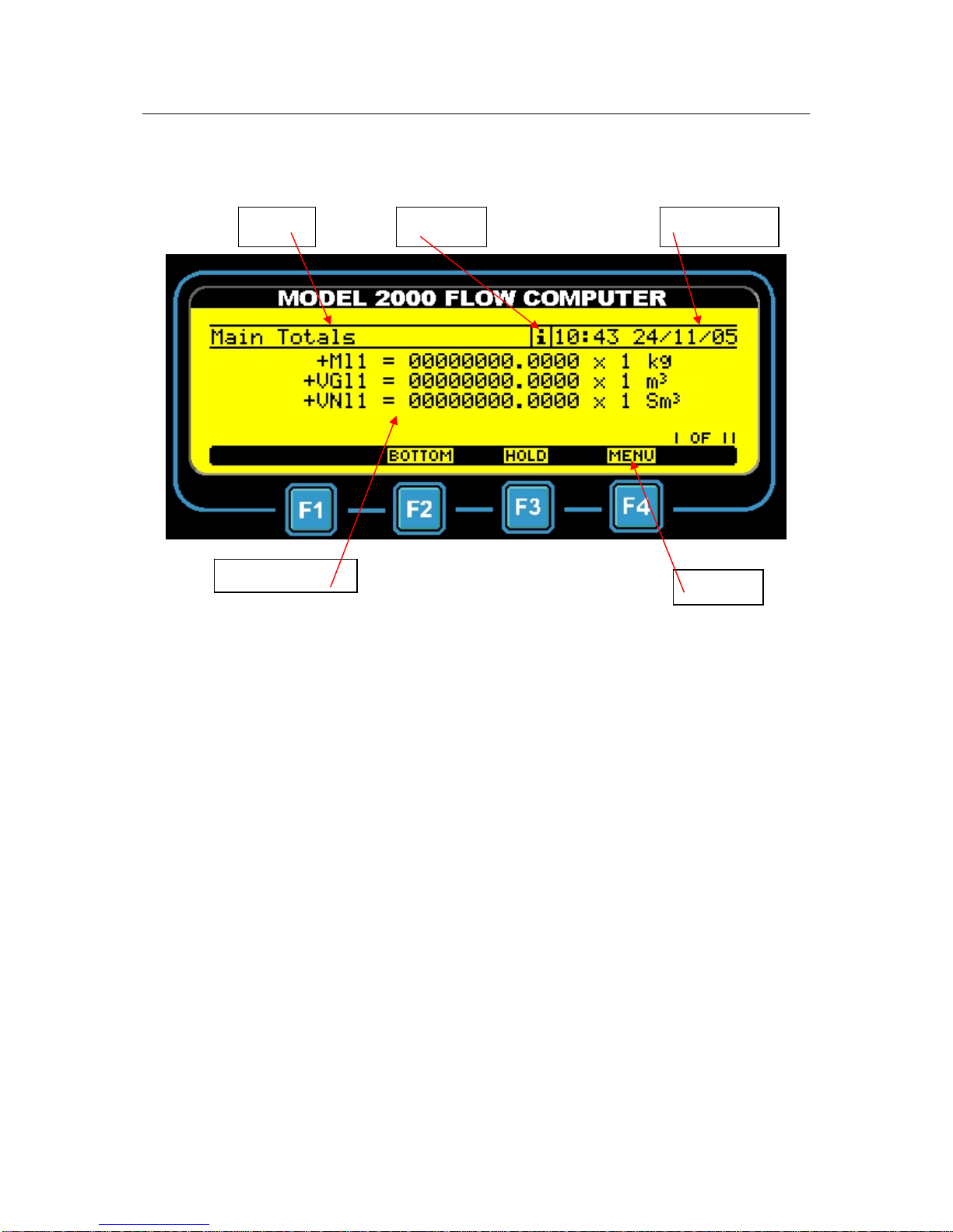
2.2.4. DISPLAY
The Display of the Model 2000 is divided into a number of sections as can be seen as follows:-
Typical Display Page
The top of the Display page shows the page title, the information symbol (if information is available on this page) and the
current Model 2000 time and date.
The centre section is the main display area this generally shows the selected data that is appropriate for this page, together
with the page number and total number of pages that applies to the current section.
The bottom line of the display is shown in reverse format and gives the current function of the four function keys F1, F2, F3
and F4.
Page Title Information Time and Date
Main Display Area Function

Model 2000 Flow Computer Instruction Manual
2.0 GENERAL DESCRIPTION
Model 2000 issue 21 Page No 8
2.2.5. MAIN MENU FUNCTIONS
The main operating Menu of the Model 2000 can be accessed in a number of ways depending upon the current operational
state of the Model 2000 and the current display page. These methods are either to select Menu using the function keys, or to
select Main Menu from the current menu list or if the unit has just been switched on and is displaying the start up page, the
Main menu will be on the display.
The items available in the Main menu item list are as follows:-
Totals
Line Conditions
∗Coriolis Meter
∗Grab Sampler
∗Chromatograph
∗Station Controller
∗PID Controller
∗Liquid Data
∗Gas Data
Settings
Preset Data
Edit
∗Output set-up
Alarms
Events
Display
System
Calibration
Board Info
∗Information
General Info
Items marked ∗will only be shown in the Main Menu if they are selected to operate.
Depending upon the type of machine set-up or connected to, when some of the above items are selected the user will be
prompted with a sub-menu to select from the following:-
Station
General
Chromatograph
Stream 1
Stream 2
Stream 3
This menu would be limited to Station, General, Chromatograph, Stream 1 and 2 if the unit was only a two stream device,
and to General, Chromatograph and Stream 1 if the unit was a single stream device.

Model 2000 Flow Computer Instruction Manual
2.0 GENERAL DESCRIPTION
Model 2000 issue 21 Page No 9
2.2.6. MAIN MENU FUNCTION Totals
This menu item is a read only display and when selected will show all the pages of flow totals availablein this machine these
will include:-
For Turbine Machines
+Vbu Uncorrected Volume from Meter “Un-haltable” i.e. always counts
+Vb Uncorrected Volume from Meter
+Vbc Uncorrected Volume corrected for meter non-linearity
+Vbcu Uncorrected Volume corrected for meter non-linearity “Un-haltable” i.e. always counts
+Vb Uncorrected Volume from Monitor
+Vn Corrected Volume
+Vnu Corrected Volume from Meter “Un-haltable” i.e. always counts
+M Mass
+Mu Mass “Un-haltable” i.e. always counts
+E Energy
+Eu Energy “Un-haltable” i.e. always counts
For Ultrasonic Machines
+Vbu Uncorrected Volume from Meter “Un-haltable” i.e. always counts
+Vb Uncorrected Volume from Meter
+Vbcu Uncorrected Volume corrected for meter non-linearity “Un-haltable” i.e. always counts
+Vb Uncorrected Volume from Monitor
+Vn Corrected Volume
+Vnu Corrected Volume from Meter “Un-haltable” i.e. always counts
+Vdry Corrected Volume of dry gas
+Vdryu Corrected Volume of dry gas “Un-haltable” i.e. always counts
+M Mass
+Mu Mass “Un-haltable” i.e. always counts
+E Energy
+Eu Energy “Un-haltable” i.e. always counts
For Wet Gas Venturimachines
+Mguc Mass gas from Venturi no correction for wetgas
+Mgc Mass gas from Venturi corrected for wet gas
+Mlc Mass liquid corrected
+Ngl Line Volume of gas
+Ngb Base Volume of gas
+Nll Line Volume of Liquid
+Nlb Line Volume of Liquid
+Mw Mass of Water
+Mc Mass of Condensate
All the above Venturi Totals are also available in un-haltable versions
For Wet Gas Venturi type 2 machines
+Mguc Mass gas from Venturi no correction for wetgas
+MgS Mass saturated gas from Venturi corrected for wet gas
+MgD Mass dry gas from Venturi corrected for wet gas
+ML Mass liquid corrected
+MTP Mass two phase product including Water
+MC Mass condensate liquid corrected
+MW Mass Water liquid corrected
+MM Mass Methanol liquid corrected
+Mhc Mass Hydro Carbon corrected
+VnG Standard Volume of gas
+VnC Standard Volume of condensate
+VnW Standard Volume of Water
+E Energy
All the above Venturi Totals are also available in un-haltable versions

Model 2000 Flow Computer Instruction Manual
2.0 GENERAL DESCRIPTION
Model 2000 issue 21 Page No 10
For Coriolis meter machines
+Ml Mass of Liquid in kg primary flow source.
+Mls Mass of Liquid in kg secondary flow source.
+VGl Volumeof Liquid at Line conditions in m3
+VNl Volume of Liquid at base conditions in m3
+Mw Mass of Water in kg.
+VGw Volume of Water at Line conditions in m3
+VNw Volume of Water at base conditions in m3
+Mc Mass of Condensate in kg.
+VGc Volume of Condensate at Line conditions in m3
+VNc Volume of Condensate at base conditions in m3
All the above Coriolis Totals are also available in un-haltable versions
Primary and secondary source from the Coriolis meter can be either serial data via Modbus communication or pulse
accumulation via pulse input.
For All machine types if enabled
+CO2 Mass of CO2
Which are then sub-divided into groups as follows:-
•Main Totals
•Alarm Totals
•Main Totals when HOLD function last operated
•Alarm Totals when HOLD function last operated
•Current 15 min, Hour, Day and Month non-accumulated Totals
•Previous 15 min, Hour, Day and Month non-accumulated Totals
•Last Day non-accumulated Totals
•Previous Hour, Day and Month accumulated Totals
•Previous Hour, Day and Month accumulated Alarm Totals
•Current Hour, Day and Month non-accumulated Alarm Totals
•Previous Hour, Day and Month non-accumulated Alarm Totals
•Last Day and non-accumulated Alarm Totals
The items will be divided into pages with a maximum of four items per page, each item will be displayed with the
corresponding symbols, scaling factors and units.
2.2.7. MAIN MENU FUNCTION Line Conditions
This menu item is a read only display and when selected will show all the pages of line conditions available in this machine
these will include:-
General sub-menu items, i.e. items that relate to the machine and not specifically to streams.
Digital Input Status The Status inputs appear as Digital i/p X.Y on the M2000 display
Where
Xis the input number 1, 2 or 3
Y is the USER Board Slot number 1, 2, 3, 4 or 5.
Stream Nsub-menu items, i.e. items that relateto the streams
Flow Rates
Peak Flow rates and Time and Date of occurrence
Line Pressure and Temperature and status
Line and Base Compressibility
Line Density
Correction Factors
Meter Information
Station sub-menu items, i.e. items that relate to station functions only in a Multistream machine.
Station Flow rates
The items will be divided into pages with a maximum of four items per page, each item will be displayed with the
corresponding symbols, scaling factors and units.
2.2.8. MAIN MENU FUNCTION Coriolis Meter

Model 2000 Flow Computer Instruction Manual
2.0 GENERAL DESCRIPTION
Model 2000 issue 21 Page No 11
This menu item is a read only display and when selected will show the status of any serially connected Liquid Coriolis Meter
and Meter data, this page will only be shown if a Coriolis M2000 type has been selected using the M2000 windows software.
The data items available are as follows:-
Current read Status Reading Data or Waiting
Last read Status OK or Comms Problem
CM Status Meter Status Information
CM Mass Meter Mass flow rate in kg/hr
CM Density Meter Density in kg/m3
CM Volume Meter Volume flow rate in m3/day
CM temperature Meter Temperature
CM pressure Meter Pressure
CM Mass and Volume Totals
The items will be divided into pages with a maximum of four items per page.
2.2.9. MAIN MENU FUNCTION Grab Sampler
This menu item is a read only display and when selected will show a sub menu as below:-
Sampler 1
Sampler 2
Sampler 1 shows the status and operational state of Liquid Grab Sampler 1 and Sampler 2 shows the same information for
Liquid Grab Sampler 2. The data items available are as follows:-
Sampler current and remaining Volume in cc
Sampler Volume in m3
Required, current and remaining Sampler pulses to fill the can
Sampler Rate in cc/m3
Can fill level in %
Grab Sampler Status
The items will be divided into pages with a maximum of four items per page.
2.2.10. MAIN MENU FUNCTION Chromatograph
This menu item is a read only display and when selected will show the status of any connected Gas Chromatograph, this
page will only be available if a gas chromatograph has been set up using the M2000 windows software. The data items
available are as follows:-
Current read Status Reading Data or Waiting
Last read Status OK or Comms Problem
Chr Stream Number
Chr Analysis N/A, Analysis or Calibrate
Chr State N/A, Idle, Analysis or Calibrate
Chr Status 1 16 bits of Status
Chr Status 2 16 bits of Status
The items will be divided into pages with a maximum of four items per page. See page 75 for details of Gas Chromatographs
that are supported and the Modbus Communication addresses that are read by the Model 2000. The above is a typical
example so notall theabove data items may be available for alltypes of Gas Chromatograph.
2.2.11. MAIN MENU FUNCTION Station Controller
This menu item is a read only display and when selected will show all the pages of data relating to the set up of the Station
Controller. This will include:-
Number of Connected units and their communication ids.
Current operating Status of Read and Writes to those units.
2.2.12. MAIN MENU FUNCTION PID Controller
This menu item is a read only display and when selected will show all the pages of available information that relate to the
Proportional, Integral and Derivative control outputs in this machine.

Model 2000 Flow Computer Instruction Manual
2.0 GENERAL DESCRIPTION
Model 2000 issue 21 Page No 12
2.2.13. MAIN MENU FUNCTION Gas Data
This menu item is a read only display and when selected will show a sub menu as below:-
Preset
Received
Used
Hourly Average
Daily Average
The menu item Preset contains all gas data max, min, hi, lo and keypad entry values.
The menu item Received contains all gas data values that have been received either from a connected gas
chromatograph or from a supervisory system or as analogue inputs, together with the status of that
number for example N/A which means not available, a value has not been received.
The menu item Used contains the gas data values that are being used in the Model 2000 and the origin of
the number i.e.Keypad, OK or LGV.
The menu items Hourly and Daily averages display the current average values for all the gas components.
The Hourly average is calculated over the last complete hour and the daily average is calculated over
the last complete day from contract hour to contract hour. The Hourly and Daily Averages can be
selected to be calculated from either received Chromatograph values, received Serial (Modbus)
values or received analogue values.
All of the items of Gas data in this machine will be divided into pages with a maximum of four items per page, each item will
be displayed withthe correspondingsymbols, scaling factors and units.
2.2.14. MAIN MENU FUNCTION Liquid Data
This menu item is a read only display and when selected will show a sub menu as below:-
Preset
Received
Used
Hourly Average
Daily Average
The menu item Preset contains Specific Gravity (relative density) Liquid data, max, min, hi, lo and keypad
entry values together with theunits of temperature measurement for liquid correction.
The menu item Received contains Specific Gravity (relative density) Liquid data values that have been
received either from a connected chromatograph or from a supervisory system or as analogue inputs,
together with the status of that number for example N/A which means not available, a value has not
been received.
The menu item Used contains the Specific Gravity (relative density) Liquid data values that are being used in
the Model 2000 and the origin of the number i.e. Keypad, OK or LGV.
The menu items Hourly and Daily averages display the current average values for Specific Gravity (relative
density). The Hourly average is calculated over the last complete hour and the daily average is
calculated over the last complete day from contract hour to contract hour. The Hourly and Daily
Averages can be selected to be calculated from either received Chromatograph values, received
Serial (Modbus) values or received analogue values.

Model 2000 Flow Computer Instruction Manual
2.0 GENERAL DESCRIPTION
Model 2000 issue 21 Page No 13
2.2.15. MAIN MENU FUNCTION Settings
This menu item is a read only display and when selected will show all the pages of Setting Information available in this
machine these will include:-
General sub-menu items that relate to the machine.
Serial Number up to 8 digits
Contract Hour 0 = Midnight
Energy Units MJ, Kwh, kcal, therms or BTU
Maintenance Mode On or Off
Chromatograph sub-menu items that relate to the gas chromatograph.
Chromatograph type Selected from a list
Communication ID Modbus id
Read Time How often data is read
Chromat status Ignore GC alarms
C6+ code % of higher components
Stream N sub-menu items that relate tothe streams
CompressibilityEquation in use
Combustion / Base Temperatures
Meter Correction Equations in use
Orifice Equations and calculation methods in use
Energy calculation using Superior or Inferior Heating Values
Total or Flow rate suspension under Low Flow conditions
Total or Flow rate suspension under Alarm conditions
Alarm Counter functions
Gas data alarm use Last Good Value or Keypad
Gas Chromatograph stream number
Station sub-menu items that relate to station functions. Only in a Multistream machine.
Sum Stream into Station Totalsor Flow rates
The items will be divided into pages with a maximum of four items per page, each item will be displayed with the
corresponding symbols, scaling factors and units.
2.2.16. MAIN MENU FUNCTION Preset Data
This menu item is a read only display and when selected will show all the pages of Pre-set Data available in this machine
these will include:-
Alarm Levels (not gas data)
All Constants
Base Conditions
Number of Pressure Sensors and On/Off for each
Pressure Sensor selection
Pressure sensor deviation and keypad values
Pressure Units and Gauge or Absolute
Number of TemperatureSensors and On/Off for each
Temperature Sensor selection
Temperature sensor deviationand keypad values
The items will be divided into pages with a maximum of four items per page, each item will be displayed with the
corresponding symbols, scaling factors and units. Any item that has no value or has not been set will be shown as --------
Table of contents
Other Elster Instromet Desktop manuals

Popular Desktop manuals by other brands


Dell
Dell Precision 7960 Service manual

Compaq
Compaq dc5850 - Microtower PC Technical reference guide

Dell
Dell Inspiron 24-5490 Setup and specifications

Lenovo
Lenovo ThinkCentre 0401 Hardware Maintenance Manual

Lenovo
Lenovo ThinsStation P320 Hardware Maintenance Manual

IBM
IBM NetVista A20 Guide de l'utilisateur