Elster Instromet enCore FC1 User manual

Flow Computer
enCore FC1
Manual
Part 2: Operating Instructions
FC1-BA2-EN a 2013-06-26

Page 2 of 78 Operating Instructions enCore FC1
Elster GmbH
Schloßstraße 95a
D - 44357 Dortmund / Germany
Tel.: +49 - 2 31 - 93 71 10 0
Fax: +49 - 2 31 - 93 71 10 99
E-mail: Support-DO@elster.com
enCore FC1 Operating Instructions Page 3 of 78
Contents
1Introduction 6
1.1Scope of Delivery 6
1.2About these Instructions 6
1.3Explanation of Symbols 8
1.3.1Presentation of Hazard Warnings 8
1.3.2Presentation of Safety Instructions 9
1.3.3Presentation of Tips and Recommendations 9
1.4Target Group Definition 9
1.5Limitation of Liability 10
1.6Applicable Standards and Guidelines 11
2Safety 13
2.1General Safety Instructions 13
2.2Intended Use 15
2.3Unauthorized Users 16
2.4Operator Liability 16
3Design and Function 18
3.1enCore and enSuite 18
3.2FC1 Functional Description 18
3.3Device Description 20
3.4Control Panel 21
3.4.1Device Keys 22
3.4.2Touch Screen 22
3.4.3Operation and Navigation within the Display 22
3.4.4Security Switch 22
3.4.5LEDs 23
3.5Interfaces (Rear Side of Device) 25
3.6Available Process Boards 26
3.6.1ExMFE5 Process Board 26
3.6.2MFE7 Process Board 27
3.6.3MSER4 Process Board 28
3.6.4MFA8 Process Board 28
Page 4 of 78 Operating Instructions enCore FC1
4Assembly and Installation 29
4.1Line Connection 29
4.2Power Supply and Grounding 31
4.3Mounting of Process Boards 31
4.4Connection Diagrams 37
4.4.1Pt100 (EEx i) via ExMFE5 Board 37
4.4.2Pt100 (EEx d) via MFE7 Board 38
4.4.3Analog Pressure Transmitter (EEx i) via ExMFE5 Board 38
4.4.4Analog Pressure Transmitter (EEx d) via MFE7 Board 39
4.4.5Analog Pressure Transmitter (EEx i) via MFE7 Board 39
4.4.6HART Transmitter (EEx i) via ExMFE5 Board 40
4.4.7HART Transmitter (EEx d) via MFE7 Board (Internal Power Supply) 41
4.4.8HART Transmitter (EEx d) via MFE7 Board (External Power Supply) 42
4.4.9HART Transmitter (EEx i) via MFE7 Board 43
4.4.10HART Transmitter (EEx d) via MFE7 Board (redundant) 44
4.4.11HART Transmitter (EEx i) via MFE7 Board (redundant) 45
4.4.12Gas Meter (Turbine): Encoder Index, 2 LF/HF Sensors (EEx i) via
ExMFE5 Board 46
4.4.13Gas Meter (Turbine): Encoder Index, 2 LF/HF Sensors (EEx i) via
MFE7 Board 46
4.4.14Gas Meter (Turbine): SMRI2 Bi-directional: 2 HF Sensors, Flow
Direction Detection (EEx i) via MFE7 Board 47
4.4.15Q.Sonic Ultrasonic Gas Meter: Serial RS485 (EEx d) via MFE7 Board 48
4.4.16FLOWSIC600 Ultrasonic Gas Meter: Serial RS485 (EEx d) via MFE7
Board 49
4.4.17Serial Interface through COM Port (CPU or MSER4 Board) 50
4.4.18Analog Output (0/4...20mA) via MFA8 Board 51
4.4.19Message Output via MFA8 Board 52
4.4.20Pulse Output via MFA8 Board 53
5Device Configuration and Commissioning 54
5.1enSuite Software 54
5.1.1System Requirements 54
5.1.2enSuite Installation 54
5.1.3Installation of the USB driver 59
5.2Device Parameterization 62
enCore FC1 Operating Instructions Page 5 of 78
5.3Commissioning the Measurement System 63
5.3.1Checking Device Settings 63
5.3.2Checking Measurement Input Values 63
5.3.3Checking Output Signals 64
5.3.4Checking Digital Communication (Modbus, etc.) 64
5.3.5Checking Measurements and Calculations 64
5.3.6Sealing (if necessary) 64
6Maintenance 65
6.1Battery Replacement 65
6.2Cleaning 68
6.3Customer Service 69
6.4Replacement Parts and Accessories 69
6.5Warranty Conditions 70
7Decommissioning / Disposal 71
7.1Storage 71
7.2Disposal 72
8Technical Data 73
8.1General 73
8.2Inputs 74
8.3Outputs 75
8.4Interfaces for Digital Communication 75
9Index 76
10Appendix 78
1 Introduction
Page 6 of 78 Operating Instructions enCore FC1
1 Introduction
1.1 Scope of Delivery
The enCore FC1's scope of delivery includes:
enCore FC1 electronic flow computer
Confirmation of conformity or factory test protocol
Dispatch list / delivery note
FC1 manual - Part 1 (Brief instruction) and Part 2 (Operating
instructions)
enSuite installation CD
USB cable (A/B type)
Accessories (plugs incl. housing)
1.2 About these Instructions
The documentation on hand is Part 2 (Operating instructions) of the overall
documentation, and describes the assembly, installation, commissioning and
maintenance of the enCore FC1 flow computer (called FC1 below).
A hard copy of this portion of the documentation is included in the delivery
scope of the FC1.
These instructions make it possible to work with the FC1 in a safe and
efficient manner.
Compliance with all the safety and handling instructions specified in these
operating instructions is a prerequisite to working with the FC1 in a safe
manner and using it properly, and for obtaining accurate measurement and
calculation results.
In addition, compliance is also necessary with the guidelines, standards,
local accident prevention regulations and general safety regulations that
apply for the FC1's area of application.

Introduction 1
enCore FC1 Operating Instructions Page 7 of 78
The entire FC1 documentation consists of three parts:
Part 1 Brief instruction
Part 1 of the documentation briefly describes the legally relevant
properties of the FC1 flow computer. Apart from topics such as General
device information and Technical data, Display and Operation, Basic
functionalities and Description of compulsory AFBs (Application
Function Blocks), there is an Appendix including approval certificates
and other legally relevant documents (if applicable). A hard copy of this
portion of the documentation is included in the scope of delivery.
Part 2 Operating instructions
Part 2 is the document on hand. A hard copy of this portion of the
documentation is included in the scope of delivery.
Part 3 Configuration of the Device Software
Description of the Basic System including SFBs
(System Function Blocks, basic functionalities)
Descriptions of available AFBs (Application
Function Blocks)
Part 3 is a composition of several documents and is delivered in
electronic form only.
This part of the manual is intended for all specialized readers who are
interested in AFB functionality details. In particular, these
documentations explain how to configure the device parameterization
according to requirements. The information provided is completed by
the parameter descriptions included in the enSuite online help (enSuite
= PC software supporting enCore devices).
These instructions are a component of the product and must be kept in the
immediate vicinity of the FC1, so installation, operational, maintenance and
cleaning personnel may access them at any time.
The graphical illustrations in these instructions serve to depict the facts that
are being explained, and are therefore not necessarily true to scale and may
differ from the actual design of the FC1.

1 Introduction
Page 8 of 78 Operating Instructions enCore FC1
The data and material properties that are presented below are
guidelines. They must be reviewed for each individual case and
corrected if necessary.
1.3 Explanation of Symbols
1.3.1 Presentation of Hazard Warnings
Hazard warnings indicate hazardous situations that may result in material
damage and bodily harm up to death if disregarded.
Hazardous warnings are presented as described below:
DANGER WORD!
Type of danger
Consequences in case of non-compliance
- Avoiding danger
The danger word signals the hazard level:
DANGER!
…indicates an immediately hazardous situation that leads to death or
severe injury.
WARNING!
…indicates a possibly hazardous situation that may lead to death or
severe injury.
CAUTION!
…indicates a possibly hazardous situation that may lead to slight or
minor injuries.
ATTENTION!
…indicates a possibly hazardous situation that may lead to material
damage.

Introduction 1
enCore FC1 Operating Instructions Page 9 of 78
1.3.2 Presentation of Safety Instructions
Safety instructions include notes and information that can lead to FC1
functions not working correctly or not working at all if disregarded.
Safety instructions are presented as described below:
Safety instruction text
1.3.3 Presentation of Tips and Recommendations
Tips include notes and information that make it easier for the user to operate
the FC1.
Tips are presented as described below:
Tip text
1.4 Target Group Definition
The present documentation is directed to qualified electricians in the fields of
switch cabinet construction and maintenance, as well as qualified personnel
with specialized knowledge in device assembly, installation and
commissioning.
The qualifications for different areas of activity are listed below:
Trained individual
was instructed by the plant operator in an informational session on the
tasks assigned to him or her, and on possible hazards in case of
improper behavior.
Specialist
has the ability, because of his or her technical training, knowledge and
experience, as well as his or her knowledge of the relevant regulations,
to carry out the work to the FC1 assigned to him or her, and to
recognize and avoid possible hazards on his or her own.

1 Introduction
Page 10 of 78 Operating Instructions enCore FC1
Gas specialist
has the ability, because of his or her technical training, knowledge and
experience, as well as his or her knowledge of the relevant standards
and regulations, to carry out work to gas systems, and to recognize
possible hazards on his or her own. A gas specialist receives training for
the specific location in which he or she works, and is acquainted with
the relevant standards and regulations.
Metrology expert
has the ability and is authorized, because of his or her technical training,
knowledge and experience, to carry out fiscally protected work to gas
systems within the scope of legal metrology. A metrology expert is
trained to work with fiscally protected devices and systems, and is
acquainted with the relevant standards and regulations that apply in
specific countries.
Qualified electrician
has the ability, because of his or her technical training, knowledge and
experience, as well as his or her knowledge of the relevant standards
and regulations, to carry out work to electrical systems, and to recognize
and avoid possible hazards on his or her own. A qualified electrician
receives training for the specific location in which he/she works, and is
acquainted with the relevant standards and regulations.
1.5 Limitation of Liability
All specifications and instructions in these operating instructions were
compiled under consideration of applicable standards and regulations, the
current state of the art and the knowledge and experience we gained over
the years.
The manufacturer assumes no liability for loss due to:
Non-compliance with these operating instructions
Use of the device not in accordance with its intended use
Use of the device by non-instructed personnel
Unauthorized device modifications

Introduction 1
enCore FC1 Operating Instructions Page 11 of 78
Technical changes
Use of non-authorized replacement parts
The actual scope of delivery may differ from the explanations and
descriptions included here in case of special device designs, the use of
additional ordering options or because of the latest technical changes.
The obligations arranged in the delivery contract apply, as do the General
Terms and Conditions, manufacturer delivery conditions and current legal
regulations that apply at the time the contract was concluded.
Read through these operating instructions carefully before
beginning any work to and with the FC1, especially before
commissioning the device!
The manufacturer assumes no liability for loss and malfunctions that
result from non-compliance with these instructions.
We reserve the right to make technical changes within the scope of
improving performance characteristics and continuous development of the
device.
1.6 Applicable Standards and Guidelines
The construction, production and operation of the FC1 are based on the
following standards and guidelines:
EN 12405-1
(Gas meters - Conversion devices - Part 1: Volume conversion)
EN 61000-6-2
(Electromagnetic compatibility - Immunity for industrial environments)
EN 61000-6-3
(Electromagnetic compatibility - Emission standard for residential,
commercial and light-industrial environments)
EN 60079-0
(Explosive atmospheres - Equipment - General requirements)

1 Introduction
Page 12 of 78 Operating Instructions enCore FC1
EN 60079-11
(Explosive atmospheres - Equipment protection by intrinsic safety "i")
EN 60079-17
(Explosive atmospheres - Electrical installations inspection and
maintenance)
EN 60079-25
(Explosive atmospheres - Intrinsically safe systems)
ISO 12213
Parts 1-3 (Natural gas – Calculation of compression factor)
ISO 6976
(Natural gas – Calculation of calorific values, density, relative density,
and Wobbe index from composition)

Safety 2
enCore FC1 Operating Instructions Page 13 of 78
2 Safety
2.1 General Safety Instructions
WARNING
Risk of explosion
A risk of explosion exists if the FC1 is improperly installed
and connected!
The FC1 must be installed outside of ex-zones 0, 1 and 2.
The FC1 can be equipped with hardware modules that are
approved as associated electrical apparatus of category ib
with intrinsically safe electrical circuits according to
EN 60079-11 (i.e. input boards with the designation ExMFE5).
The FC1 is therefore suitable for being connected to
transmitters, pulse and signal generators that are located in
hazardous areas (e.g. zone 1). A mixed connection of
intrinsically safe and non-intrinsically safe circuits to these
hardware modules is not permitted.
Only intrinsically safe protection class [EEx ib] II C
temperature and pressure transmitters must be connected to
the respective ExMFE5 connection terminals.
Only pulse transmitters of protection class [EEx ib] II C must
be connected to the respective ExMFE5 connection terminals.
All signals from the potentially explosive area (zone 0, zone 1,
zone 2) that are connected to hardware modules other than
ExMFE5 must be blocked off by means of appropriate ex-
isolators.
The regulations in the relevant standards, especially
EN 60079-0, EN 60079-11, EN 60079-17 and EN 60079-25,
must be obeyed unconditionally.

2 Safety
Page 14 of 78 Operating Instructions enCore FC1
The following safety and warning instructions must be observed
unconditionally:
Any individual appointed to perform work to or with the FC1
must read and understand these operating instructions before
beginning work. This also applies if the individual concerned
has already worked with such a device or a similar one, or was
instructed by the manufacturer.
In order to avoid risks and to ensure that the FC1 performs in
an optimal manner, no changes or modifications that were not
expressly authorized by the manufacturer may be performed to
the device.
The FC1 must not be exposed to temperatures below -25°C or
above +60°C during storage.
A temperature that is between -10°C and +55°C must be
ensured while the FC1 is being operated.
The FC1 is supplied with power by means of 24V DC, and this
power supply must be protected externally using a 1A time-
delay fuse.
The grounding is connected to PE of the power supply socket
for equipotential bonding.
The range limits stated in the certificates of conformity for the
boards to be connected (e.g. EC type examination certificate
ATEX) must be observed.
If the device is used within the scope of legal metrology, the
range limits that are stated in the respective approval
certificate (e.g. EC type examination certificate MID) must be
observed.
Section 3.6: Available Process Boards contains a description of
process boards.
Safety 2
enCore FC1 Operating Instructions Page 15 of 78
2.2 Intended Use
The FC1 is designed and constructed solely for its intended use as
described here.
The FC1 is a process computer that handles the information of external
measurement devices and signal transmitters being connected to the FC1
device.
The FC1 is primarily used for gas measurement. In this case, the main task
of the device is to convert the gas volume measured at operating conditions
to base conditions (volume conversion). Additionally, the related thermal
energy and mass can be calculated. The measured and/or calculated data
can be logged and monitored.
The FC1 device may also carry out other functions and calculations (e.g. a
mass or volume conversion for liquids). Please refer to Part 3 of the FC1
Manual for a description of available functions (AFBs).
In addition, the FC1 can be used to measure, record and monitor other
process signals.
Compliance with all the specifications in these operating instructions also
falls under the device's intended use.
Any use of the FC1 that goes beyond or deviates from its intended use is
considered a misuse of the device, and may lead to hazardous situations.
Claims of any kind due to loss resulting from non-intended use of the device
are excluded.
2 Safety
Page 16 of 78 Operating Instructions enCore FC1
2.3 Unauthorized Users
Individuals whose ability to react is impaired, e.g. because of drugs, alcohol
or medication as well as physical or health restrictions are not permitted to
operate, assemble or configure the device.
2.4 Operator Liability
The FC1 is used in industrial applications. The FC1 operator is therefore
subject to legal obligations of occupational health and safety.
In addition to the safety instructions in these operating instructions, current
regulations of safety, accident prevention and environmental protection must
be observed for the FC1 area of application.
The following items especially apply:
The operator must ensure compliance with the current regulations of
safety, accident prevention and environmental protection that apply for
the overall system in which the FC1 is integrated.
The operator must keep himself/herself informed of the applicable
occupational health and safety regulations, and determine, over the
course of a risk assessment, the additional risks that arise from the
specific working conditions when the FC1 is being used. The operator
must include these items in the form of operating instructions for the
FC1.
The operator must review, over the entire operational life of the FC1,
whether the operating instructions prepared by him or her correspond to
the current status of the bodies of regulations, and revise the
instructions if necessary.
When selecting personnel to operate the device, make sure you
comply with the specific regulations of the overall technical plant
that concern age and occupation.

Safety 2
enCore FC1 Operating Instructions Page 17 of 78
The operator must definitively regulate and establish the responsibilities
for FC1 assembly, connection, commissioning, operation and
maintenance.
The operator must ensure that all employees who work with the FC1
have read and understood these operating instructions. In addition, the
operator must train these personnel at regular intervals and inform them
of the risks involved with the device.
The operator of the overall system in which the FC1 is integrated must
provide personnel with the required protective equipment.
In addition, the operator is responsible for ensuring the FC1 is always in
technically perfect condition. The following items therefore apply:
The operator must ensure that the installation and maintenance work
described in these operating instructions are performed properly.
The operator must have all safety installations checked regularly to
ensure they function correctly and are complete.
3 Design and Function
Page 18 of 78 Operating Instructions enCore FC1
3 Design and Function
3.1 enCore and enSuite
enCore is the name of an Elster product platform for sophisticated
measuring instruments. All enCore devices are based on the same hardware
components and software concepts.
enSuite is the name of the PC software that supports enCore devices along
with a number of other Elster devices. The enSuite software provides tools
for configuration, parameterization, diagnosis, software download and other
services.
The enCore FC1 device is a process computer based on the enCore
platform.
3.2 FC1 Flow Computer: Functional Description
The FC1 is a process computer that is primarily used as flow computer for
natural gas, i.e. for measuring and calculating the gas flow (flow conversion).
Please refer to Part 3 of the FC1 manual for information about further fields
of application.
If the FC1 is used for flow conversion, various measuring instruments have
to be connected to the device (gas meters, pressure transmitters,
temperature transmitters and optional gas quality measurement devices).
The FC1 has different interface options available for each of these
measuring instrument types:
Device Type Connection Option
Gas meter Pulse interface for turbine, rotary piston or
other pulse-generating gas meters.
Serial interface for ultrasonic gas meters via a
manufacturer-specific digital protocol
Interface for gas meters with an Encoder index
Design and Function 3
enCore FC1 Operating Instructions Page 19 of 78
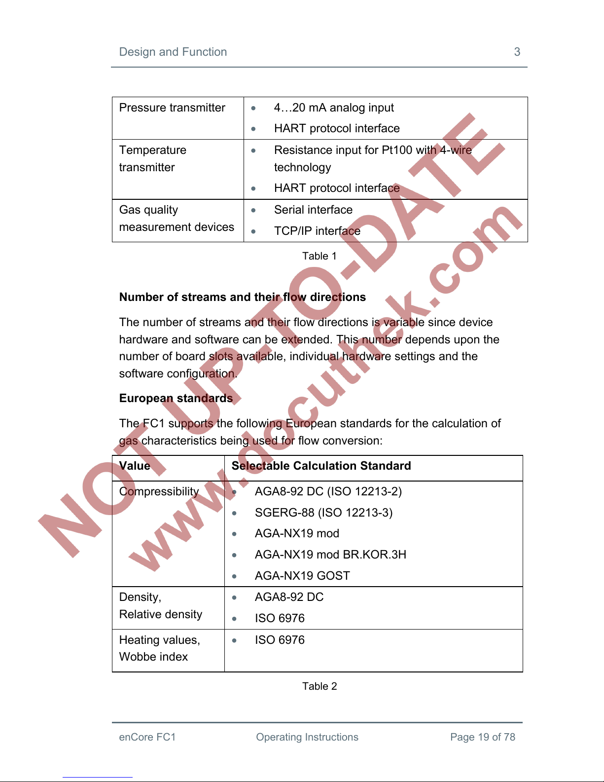
Pressure transmitter 4…20 mA analog input
HART protocol interface
Temperature
transmitter
Resistance input for Pt100 with 4-wire
technology
HART protocol interface
Gas quality
measurement devices
Serial interface
TCP/IP interface
Table 1
Number of streams and their flow directions
The number of streams and their flow directions is variable since device
hardware and software can be extended. This number depends upon the
number of board slots available, individual hardware settings and the
software configuration.
European standards
The FC1 supports the following European standards for the calculation of
gas characteristics being used for flow conversion:
Value Selectable Calculation Standard
Compressibility AGA8-92 DC (ISO 12213-2)
SGERG-88 (ISO 12213-3)
AGA-NX19 mod
AGA-NX19 mod BR.KOR.3H
AGA-NX19 GOST
Density,
Relative density
AGA8-92 DC
ISO 6976
Heating values,
Wobbe index
ISO 6976
Table 2

3 Design and Function
Page 20 of 78 Operating Instructions enCore FC1
Dependent on the field of application, other European or International
standards are supported as well.
3.3 Device Description
The FC1 is housed in a 19“ casing with a mounting width of 1/3 (max. 4
process boards) or a mounting width of 1/2 (max. 7 process boards). The
touch screen as well as 2 function keys and 5 navigation keys for operation
are located on the front of the device. In addition, the USB port, security
switch and two status LEDs are located on the front of the device.
At the rear side of the device, the CPU board provides a TCP/IP interface
and two RS232 / RS422 / RS485 serial interfaces. These interfaces are
provided in order to connect gas quality measurement devices or other
devices that have a protocol interface.
Various other I/O boards can be mounted from the rear side of the device.
The maximum number of boards depends upon the housing design. A
maximum of four process boards can be installed in a device with a
mounting width of 1/3, while a maximum of seven can be installed in a
device with a mounting width of 1/2.
The configuration of the I/O board mounting is variable. In principle, any I/O
board can be inserted into any slot. Dependent on the board type, there may
be individual restrictions (please refer to section 3.6, process board
descriptions).
The following board types are currently available:
ExMFE5 Ex input board
MFE7 input board
MFA8 output board
MSER4 serial process board
Section 3.6 contains a description of process boards.
Other manuals for enCore FC1
1
Table of contents
Other Elster Instromet Desktop manuals


 Specifications")
