ELT eSMART iLC PRO 25/200 1050-XR Series User manual
USER GUIDE
Fully PROGRAMMABLE control gear for LED modules
GU-001/05/18-EN
ORC<5%

www.elt.es
2
1. INTRODUCTION 4
1.1. The eSMART technology...................................................................................................... 4
1.2. Applications........................................................................................................................... 4
1.3. Classication and symbols................................................................................................... 4
1.4. General features of the drivers ............................................................................................. 4
1.5. Portfolio ................................................................................................................................. 5
2. ELECTRICAL FEATURES 6
2.1. Electrical parameters ............................................................................................................ 6
2.2. Electrical insulation ............................................................................................................... 7
3. THERMAL CHARACTERISTICS AND LIFETIME 8
3.1. Temperature inside the casing (tc) ...................................................................................... 8
3.2. Ambient temperature (ta)...................................................................................................... 8
3.3. Lifetime .................................................................................................................................. 8
4. PROTECTION 9
4.1. Short circuit protection ......................................................................................................... 9
4.2. Overload and open circuit protection ................................................................................... 9
4.3. Thermal protection ................................................................................................................ 9
4.4. Out-of-range mains voltage protection .............................................................................. 10
4.5. Shock wave protection........................................................................................................ 10
5. FUNCTIONALITIES 11
5.1. Adjustable output current (AOC) ........................................................................................ 11
5.2. LED module thermal protection (MTP) .............................................................................. 12
5.3. LED module constant lumen output (CLO) ........................................................................ 13
5.4. LED module end-of-life alarm (EOL)................................................................................... 14
5.5. Programmable start-up time (PST) .................................................................................... 14
5.6. Monitoring parameters and events .................................................................................... 15
6. DIMMING METHODS 16
6.1. DALI Mode ........................................................................................................................... 16
6.2. 1-10V / 0-10V mode ............................................................................................................ 17
6.3. ActiDIM mode...................................................................................................................... 19
6.4. Corridor / Parking mode ..................................................................................................... 22
6.5. ActiDIM mode with Corridor / Parking .............................................................................. 23
6.6. LineSwitch mode................................................................................................................. 24
6.7. MainsDIM mode .................................................................................................................. 25
6.8. ON/OFF mode...................................................................................................................... 26

3
www.elt.es
7. STELARIATM REMOTE STREET LIGHTING MANAGEMENT SYSTEM 27
8. INSTALLATION 30
8.1. General observations .......................................................................................................... 30
8.2. Installation in luminaires..................................................................................................... 30
8.3. Connecting the drivers ........................................................................................................ 30
8.4. Protective switches............................................................................................................. 32
9. ELECTROMAGNETIC COMPATIBILITY 34
10. MECHANICAL FEATURES 35
11. DRIVER CONFIGURATION 36
11.1. iSOFT.................................................................................................................................. 36
11.2. iProgrammer...................................................................................................................... 36
11.3. Quick start guide ............................................................................................................... 37
11.4. Factory default conguration............................................................................................ 38
12. MARKINGS AND INDICATIONS 39
13. APPLICABLE STANDARDS 40
14. PRODUCT WARRANTY 41
15. DISCLAIMER 42

www.elt.es
4
1. INTRODUCTION
Thank you for choosing control gear for LED modules designed and manufactured by ELT (Especialidades
Luminotécnicas S.A.U.). This user guide will help you learn about eSMART technology and congure your control
gear so that it can be correctly integrated into your luminaire.
We advise you to check the latest available version of this document on the ELT website, www.elt.es/en.
1.1. The eSMART technology
Thanks to its functionalities and the programmable and congurable dimming methods it incorporates, control gear
equipped with eSMART technology offers full flexibility in the design of the lighting system, perfectly adapting the
luminaires to any application and surroundings where they are to be installed.
1.2. Applications
ELT drivers with eSMART technology are the ideal street lighting solution of today and tomorrow, achieving optimal
efciency in every lighting point, accompanied by the best operational features and maximum energy saving, which
helps reduce both economic costs and CO2 emissions into the atmosphere throughout the lifetime of the street
lighting system.
These drivers can be used in an innite number of applications such as street lighting, roads, monuments, sports
facilities and industrial premises.
1.3. Classication and symbols
The nomenclature of eSMART control gear, taking an example the iLC PRO 75/200…1400-XR, is described as follows:
▪iLC: Constant current control gear equipped with eSMART technology.
▪PRO: All functionalities and programmable methods are available.
▪75: 75W of maximum output power.
▪200…1400: Constant current output in milliamps in which regulation is permitted.
▪XR: Casing format.
1.4. General features of the drivers
The main features of the iLC control gear incorporating eSMART technology are as follows:
▪Build-to-use drivers with insulation double or reinforced insulation. IP20 ingress protection.
▪Suitable for installation in Class I and Class II luminaires.
▪Wide range of input voltages.
▪High power factor.
▪Low harmonic distortion.

5
www.elt.es
▪Low standby power consumption.
▪Low output ripple current.
▪High quality light without flickering.
▪Programmable by modulating output current size.
▪Wide range of output current regulation.
▪Congurable functionalities for an optimal lighting system design:
- Adjustable output current (AOC).
- LED module thermal protection (MTP).
- LED module constant lumen output (CLO).
- LED module end-of-life alarm (EOL).
- Programmable start-up time (PST).
- Monitoring parameters and events.
▪Different regulation methods can be selected, adapting each lighting point to the needs of the installation:
- DALI.
- 1-10V / 0-10V.
- ActiDIM: stand-alone and dynamic dimming system that adapts to night hours.
- Tourist ActiDIM mode: this feature can be activated as part of the ActiDIM regulation mode, to establish exceptions
to the stand-alone dimming during a specic period.
- Parking mode: light regulation via presence detectors.
- ActiDIM Parking: combines stand-alone dimming with presence detectors.
- LineSwitch: lineswitch dimming.
- MainsDIM: head-end dimming by varying the mains voltage.
- ON/OFF: no regulation.
▪Compatible with the STELARIATM remote street lighting management system.
▪Short circuit, overload and open circuit protection.
▪Control gear thermal protection.
▪Protection against grid variations and power surges.
▪Electronic circuit fully protected against humidity.
▪Excellent thermal performance and extensive working temperature ranges.
▪Up to 100,000h lifetime.
1.5. Portfolio
Ref nº Model Version compatible with the STELARIATM
remote wireless management system
9916164 iLC PRO 25/200...1050-XR 9916165
9916153 iLC PRO 40/200...1050-XR 9916154
9916151 iLC PRO 75/200...1400-XR 9916152
9916155 iLC PRO 110/200...1050-XT
9916166 iLC PRO 150/200...1050-XT

www.elt.es
6
2. ELECTRICAL FEATURES
2.1. Electrical parameters
The iLC PRO control gear with eSMART technology has a very extensive operating area, perfectly adjusting the
operating point required in the design of each luminaire and each lighting system. The result is full flexibility, easily
adapting to the continuous and fast evolution being experienced by LED technology lighting.
The operating area of the drivers is dened by the maximum and minimum load voltage that can be connected, by the
maximum and minimum output current that can be programmed and by the maximum working power.
The operating point is dened by the maximum voltage of the LED module to be connected and the current which it
is going to supply. This operating point must be within the operating area of the selected driver.
In the iLC PRO family, the operating area of one model partially overlaps with that of the higher output model, ensuring
a continuity that effectively responds to every operating point. When the dened operating point falls within the
operating area of several drivers, selecting the device with the lowest assigned power will provide it with the best
electrical output values in terms of THD, power factor and efciency; while selecting the device with the highest
assigned power will provide a lower working temperature and as such, a longer service life. Generally, if the luminaire
has a good thermal design, the rst option is usually the recommended selection.
The iLC PRO control gear with eSMART technology permits a wide range of the supply voltage that, in addition to
becoming a solution suited to a host of installations, guarantee stable and reliable operation in the face of fluctuations
in the values of the mains grid voltage.
In terms of efciency, the power factor, THD and dimming range of the iLC PRO drivers are positioned in the high
performance segment of the lighting sector.
NOTE:
The technical specications of each model and their corresponding data sheets can be viewed and are available for download via
the ELT website at www.elt.es/en
Vout (V)
Iout (mA)
Operating area
Vout max
Vout min
Iout min Iout max
Maximum driver output
Operating point
(V module, I module)

7
www.elt.es
2.2. Electrical insulation
Control gear with eSMART technology has been designed in accordance with the EN 61347-1 and EN 61347-2-13
safety standards for double or reinforced insulation against electric shocks resulting from contact with accessible
parts.
The insulation between the primary and secondary circuits, as well as between every circuit and the functional earth,
is set out in the following table:
Functional
earth Input
voltage DALI 0-10V LED module/external NTC
/ STELARIA
Functional earth XDouble Double Double Double
Input voltage Double X Main Main Double
DALI Double Main X Main Double
0-10V Double Main Main X Double
LED module/external NTC / STELARIA Double Double Double Double X
NOTE:
When the devices are built into luminaires, the cabling between the different components must observe the insulation class for
which these lighting xtures have been designed, as well as comply with the EN 60598 standard.

www.elt.es
8
3. THERMAL CHARACTERISTICS AND LIFETIME
The thermal operating conditions of the control gear are a critical factor for its lifetime and for the LED street lighting
system into which it is integrated. This is why an understanding of the factors and parameters relating to this aspect
is essential.
Control gear equipped with eSMART technology has been designed to offer maximum performance with the best
thermal efciency.
Once the drivers have been integrated into the lighting system, the thermal efciency and lifetime depend on factors
such as the connected load, luminaire design, its capacity to dissipate the heat generated inside the unit and the
relative position of each of its components.
3.1. Temperature inside the casing (tc)
The parameter to control in order to ensure correct operation and life expectancy is the temperature inside the casing
at a point called tc. The tc is a point of reference that represents the conditions under which the driver’s internal
components are working. Particular care must be taken to ensure that the maximum limits specied for each model
are not exceeded.
The simplest way to measure the temperature at this point is by means of a thermocouple attached at the place
indicated on the casing of each driver once thermal stability has been achieved.
NOTE:
The eSMART drivers from the PRO range incorporate a diagnostic mode that indicates the internal temperature value of the driver.
This is for guidance purposes only as it does not necessarily coincide with the tc value.
3.2. Ambient temperature (ta)
The eSMART drivers have been designed to be able to operate within a very wide ambient temperature range. The
maximum ambient temperature limit depends on the operating point, the value of the connected load and, largely, to the
design of the luminaire itself and its ability to dissipate heat outwards.
The maximum permitted ambient temperature for control gear can serve as a guideline or an indicator of the
conditions under which that device is able to work, however must not be used as the control parameter to guarantee
its estimated lifetime.
With the aim of ensuring reliable ignition in ambient temperatures of less than -25ºC, the drivers power up gradually,
applying a start-up process that lasts for a maximum of 10 seconds. Gradual start-up takes place irrespectively of
the driver conguration.
3.3. Lifetime
The eSMART control gear can achieve up to a 100,000 hour lifetime depending on the working temperature at point
tc.
NOTE:
Thermal data and the lifetime of each model can be viewed on their corresponding data sheets, available for download via the ELT
website at www.elt.es/en

9
www.elt.es
4. PROTECTION
The eSMART technology control gear from ELT is equipped with internal protection to ensure that the drivers and
every component of the luminaire in which they are installed operate correctly.
4.1. Short circuit protection
In the case of a short circuit in the load terminals, the driver disconnects the power and goes into protection mode,
in which it remains as long as the fault continues. This protection automatically resets so that when the short circuit
is resolved, the driver comes out of protection mode and reconnects to the power supply.
4.2. Overload and open circuit protection
In the event of an overload or open circuit, the driver disconnects the power and goes into protection mode.
When occasional situations of overload or open circuit are identied in the output terminals, the protection mode
automatically resets. This means that once the fault is resolved, the driver comes out of protection mode and
reconnects to the power supply.
Should overloads or open circuit events repeat over time with a high level of frequency, or if such events persist,
protection mode will not automatically reset and it will be necessary to disconnect the mains power for at least a
few seconds.
If the driver is connected at a load lower than that permitted for the operating area, it will flicker as long as it remains
connected.
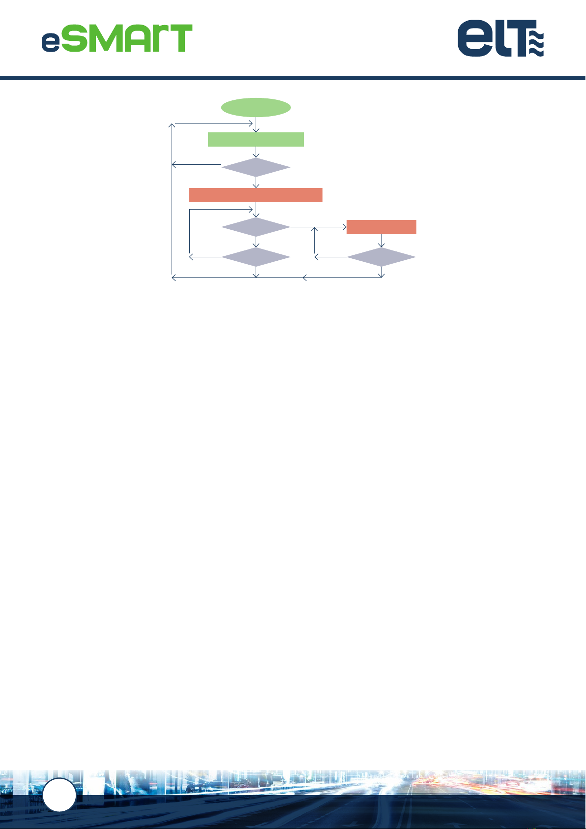
4.3. Thermal protection
Drivers with eSMART technology benets from thermal protection, meaning that when a temperature excess is
detected, the power supplied is reduced or even switched off.
If, under normal operating conditions, the temperature at tc exceeds its maximum permitted value by 5ºC, the driver
will reduce the power supplied to the load by 25%.
If, during power reduction mode, the temperature at tc continues to rise until it exceeds its maximum permitted value
by 7ºC, the driver disconnects the power.
While in thermal protection mode, having reduced or cut off the power, if the temperature at the tc reduces to 6ºC or
lower than its maximum permitted value, the driver will return to its initial normal operating mode.
This process is illustrated in the flowchart on the following page:
www.elt.es
10
4.4. Out-of-range mains voltage protection
In the event of a low mains voltage value that is between the permitted minimum and the brownout value, the driver
will remain on. If this situation continues over time resulting in over-heating, the driver will reduce the power supplied
to the load and even disconnect it in extreme cases.
In the event that a mains voltage value is less than the brownout value, the driver switches itself off for protection.
In the event that a mains voltage is above the maximum permitted value, the driver will remain on, generating stress
on its internal components and potentially affecting its lifetime. Possible adverse effects are increased the greater
the value and the longer the time that the power surge continues.
Even though the drivers are able to withstand power surges of 380Vac for 2 hours, extreme care must be taken to
avoid this type of situation.
4.5. Shock wave protection
Drivers equipped with eSMART technology from the PRO range are designed to offer improved protection of the
supply terminals against shock waves such as those caused by radio storms. They benet from levels of protection,
in both differential and common modes, that are higher than the minimums dened by the immunity requirements
for lighting equipment under EN 61547.
▪Protection in differential mode (L - N): 6kV / 3kA
▪Protection in common mode (L - Earth / N - Earth): 8kV
If higher levels of protection are required, external devices can be added to the luminaire or to another point in the
street lighting installation.
NOTE:
Fault conditions and the response of each model can be viewed on their corresponding data sheets, available for download via the
ELT website at www.elt.es/en
Normal operating
25% power reduction
Standby (OFF)
NO
NO
YES
YES
NO
YES YES
tc > tc max. +5º
tc < tc max. -6º tc < tc max. -6º
tc > tc max. +7º
Power on
11
www.elt.es
5. FUNCTIONALITIES
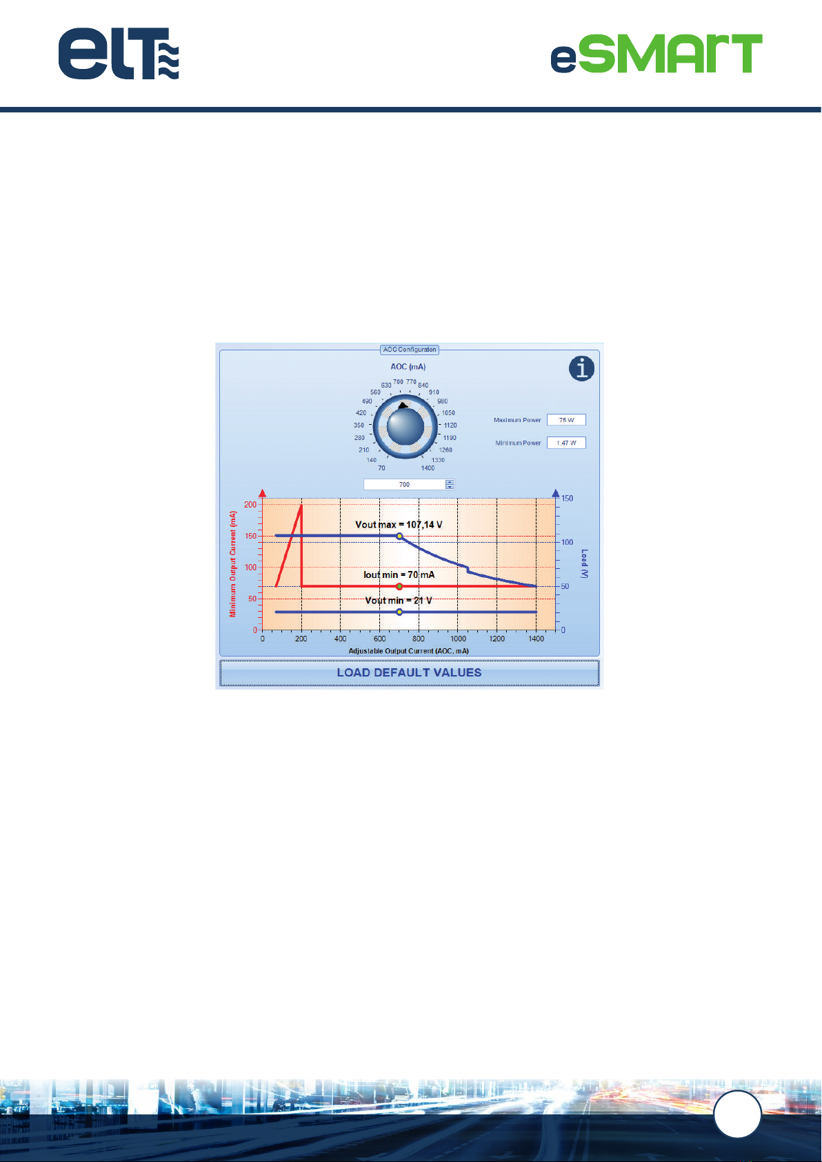
5.1. Adjustable output current (AOC)
The adjustable output current (AOC) is a feature that congures the nominal value of the output current from a driver
with eSMART technology.
The output current value selected is understood to be the nominal value used to achieve 100% of the light level in any
of the selected dimming modes that can be programmed within the entire permitted range.
www.elt.es
12
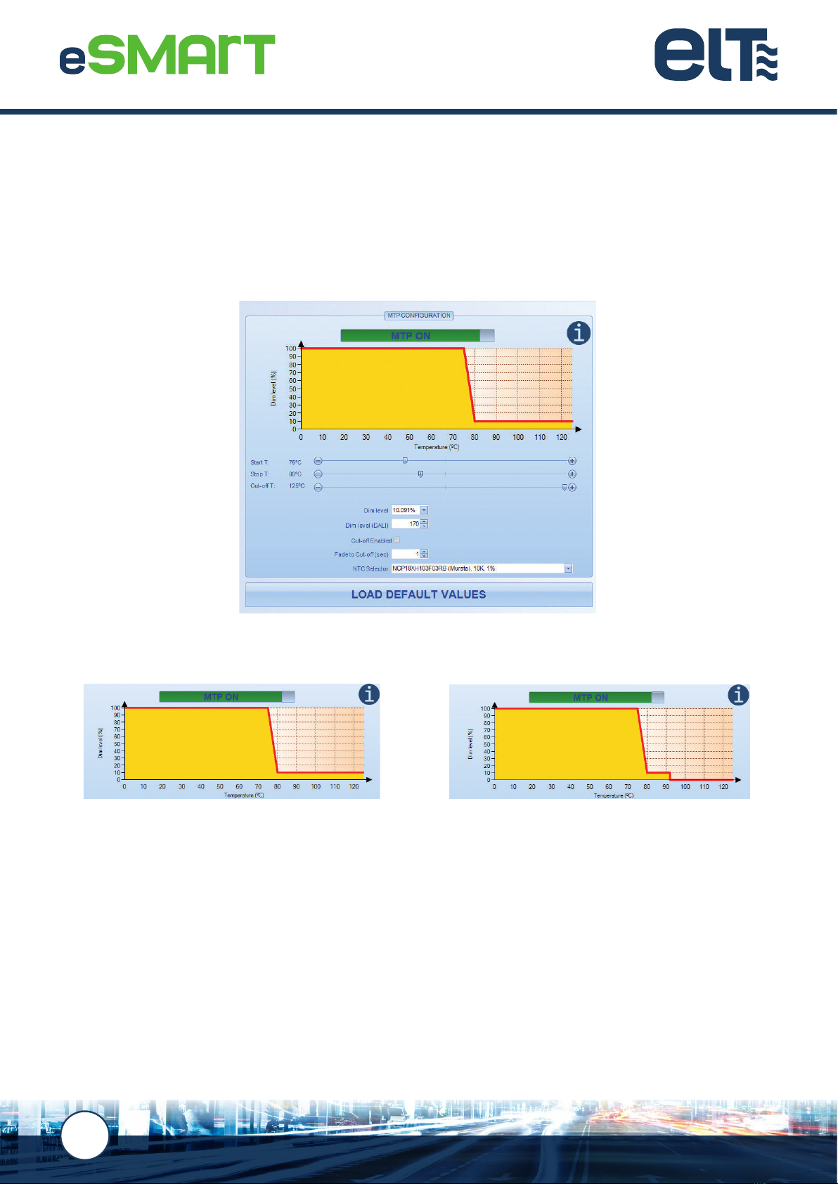
5.2. LED module thermal protection (MTP)
This feature activates a thermal protection for the LED module, controlling its temperature via an external NTC
located inside the module itself.
It has to be congured so that the driver regulates the output when the reading provided by the external NTC indicates
that the temperature at the tc point of the LED module has exceeded the maximum value that guarantees its expected
lifetime. The parameters to be dened are the “start temperature”, the “stop temperature” and the “dimming level”.
The “cut-off enabled” option can be activated which makes the driver turn off the LED module if the read temperature
exceeds a value dened as the “cut-off temperature”.
In the event that the LED module switches off because it has reached the “cut-off temperature” value, the driver
automatically switches back on at the maximum dimming level when the read temperature is 5ºC below the “start
temperature”.
So that the values of the measured temperatures are correct and can be handled by the driver, an external NTC has
to be selected and used from one of the following four commercial references:
▪NCP18XH103F03RB, 10k, 1%, 0805, MURATA.
▪NCP15XW153E03RC, 15k + 390R series, 3%, 0402, MURATA.
▪NCP18XW153J03RB, 15k, 3%, 0402, MURATA.
▪NTCS0805E3153GMT, 15k, 2%, 0805, VISHAY.
WARNING: connecting active signals to the external NTC terminals could run the risk of a breakdown.
Cut-off temperature deactivated Cut-off temperature activated
13
www.elt.es
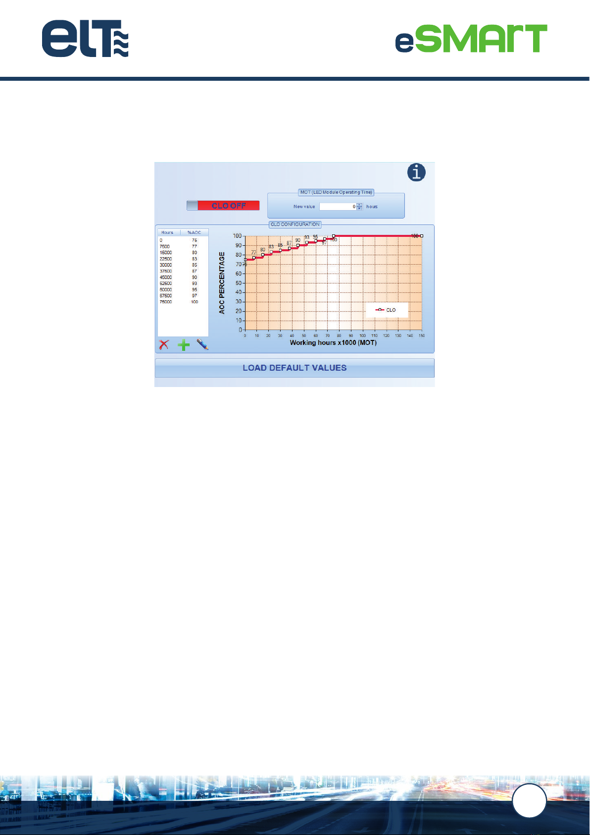
5.3. LED module constant lumen output (CLO)
This feature allows a gradual increase curve of the output current over time to be dened for the constant lumen
output depreciation of the LED module.
To correctly use and congure this functionality, the depreciation curve of the LED module lumen output to be
supplied must be known. This curve can differ for the different LED modules on the market and depends on both the
operating point and the thermal conditions under which it is working.
Based on this information, a table can be dened to incrementally assign an output current value for each operating
interval, so that the loss of LED module lumen output during that period is compensated.
The output current value can be assigned in increments of 1% within a range from 0 to 100%, where 100% is the value
dened by the AOC. The intervals can be congured in steps of 500 hours.
To synchronise the compensation curve congured by the CLO with the actual lumen output depreciation, the MOT
parameter, “the LED module operating time”, must be entered so that it coincides with the actual operating hours of
the LED module.
WARNING: The MOT value is also used for the EOL functionality.

www.elt.es
14
5.4. LED module end-of-life alarm (EOL)
This functionality provides a visual signal indicating that the LED module has reached the end of its lifetime and as
such, its replacement is recommended.
To congure this functionality, the number of hour’s life expectancy for the LED module has to be selected in addition
to the actual time that the module has been working.
The driver will make the LEDs flicker for 3 seconds after power-on when the actual operating time reaches the
expects lifetime, after which it will continue its normal operation.
5.5. Programmable start-up time (PST)
This feature is able to congure a smooth and pleasant start-up, avoiding an abrupt sensation when the street
lighting switches on.
0%
50 %
100 %
30 seg. Time
600 seg.
Lumen flow level

15
www.elt.es
Activation of the PST functionality can only take place in the ON/OFF, 1-10V and 0-10V modes. Start-up duration,
from the moment the mains voltage is switched on to achieving 100% output current, can be congured between 3
and 600 seconds, in increments of 1 second.
NOTE:
Conguring a smooth start-up using the PST functionality does not reduce the peak and width values of the inrush current.
5.6. Monitoring parameters and events
Control gear equipped with eSMART technology records numerous events in its non-volatile internal memory along
with the maximum and minimum values of different parameters and operating times in different modes, relating to
the control gear itself as well as to the LED modules its drives.
Real time data recorded and the parameters can be monitored by the user via the iSOFT conguration software and
by means of the STELARIATM remote street lighting management system.
www.elt.es
16
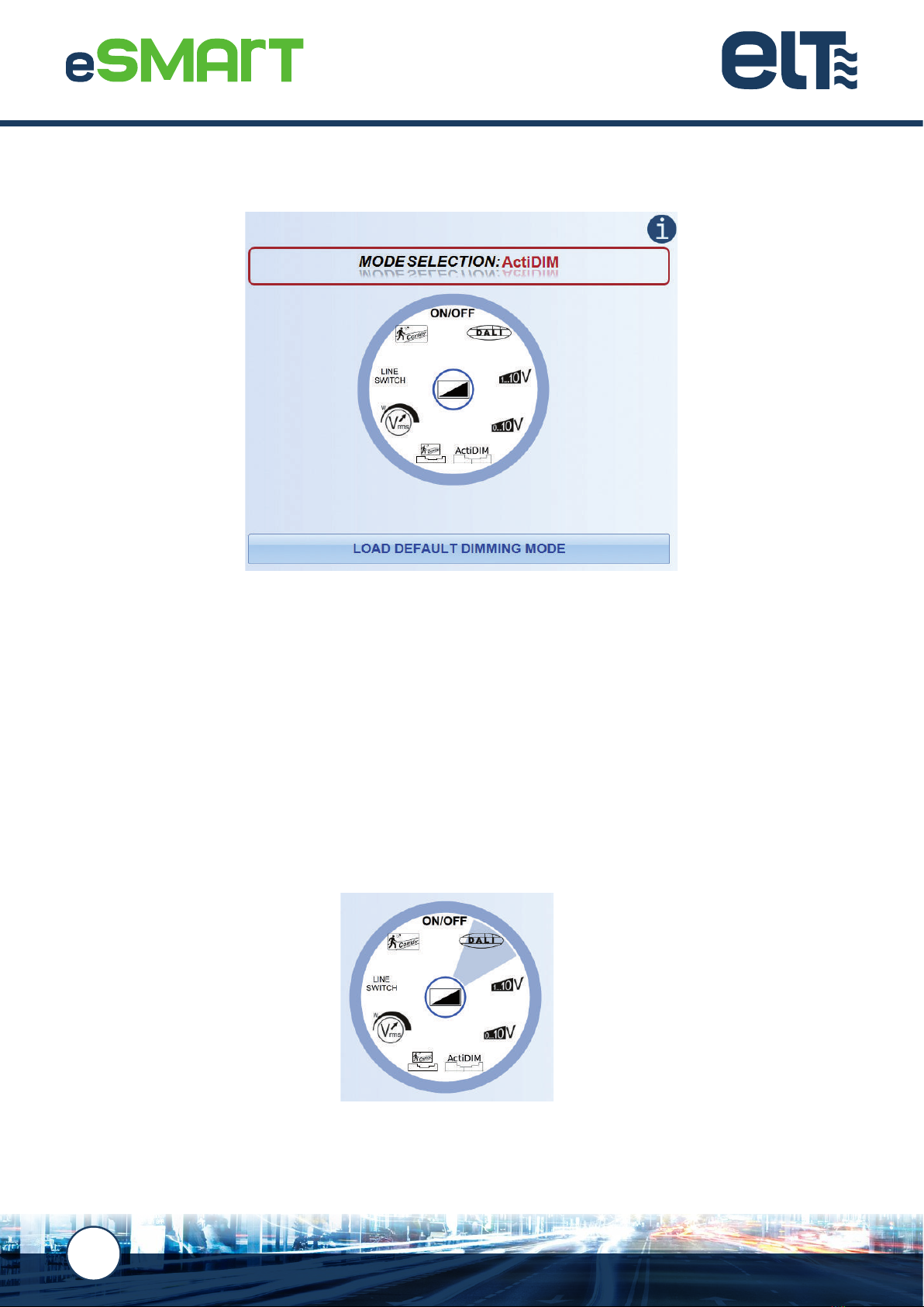
6. DIMMING METHODS
Control gear with eSMART technology is able to select the most suitable dimming method for each application. The
choice of a specic dimming mode activates its conguration parameters and deactivates other dimming methods.
Dimming is achieved through the amplitude modulation (AM) of the output current, obtaining flicker-free light at each
regulation point
The main features of each method are explained below.
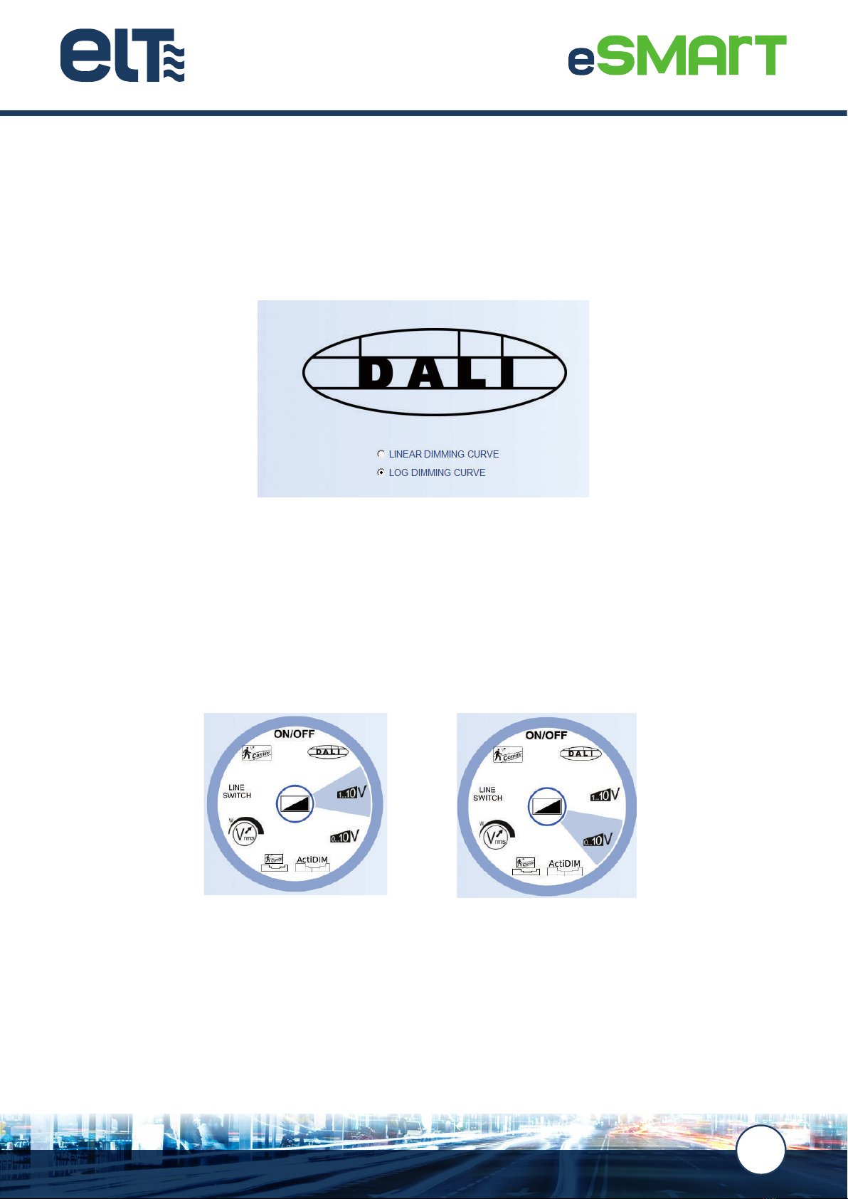
6.1. DALI mode
DALI (Digital Addressable Lighting Interface) is a digital and addressable communication interface for lighting
systems, standardised in line with EN 62386 that guarantees the correct operation between devices produced by
different manufacturers.
17
www.elt.es
Communication between programmable control gear and other DALI devices (sensors, control panels or other
peripherals) takes place via two cables and is two-way, enabling dimming, conguration and consultation commands
to be sent.
By selecting this method, the user can choose between a logarithmic or linear dimming curve.
All the information relating to this dimming system is explained in the DALI standard in line with which the eSMART
technology drivers have been designed.
6.2. 1-10V / 0-10V mode
This dimming system is able to vary the light flow by means of an analogue control signal that reaches the drivers
via an additional two-wire control line, whose positive and negative polarity must be observed when making the
connection.
This one-way system, in which the control information only flows from the controller towards the control gear, is not
addressable, given that every device connected by cable to the control line reacts to a set point.
The analogue control signal is a continuous voltage level within a range from 0V to 10V. This signal can be obtained
directly from an active control device (analogue control cards or power supply sources) or indirectly from a passive
control device (variable resistance or potentiometer) through which the output current generated by the devices in
their control terminals circulates.
www.elt.es
18
To ensure that these active control devices work correctly, they must have the capacity to absorb a quantity of
current greater than that generated by all the connected devices together.
Where a potentiometer is used for regulation, this device must have the resistance value indicated in the electric input
parameters of the driver. When various devices are going to be connected to the same potentiometer, the following
formula has to be applied to calculate its resistance value, adequately sizing it in terms of the power to dissipate.
The ratio of the resistance value of the potentiometer compared to the control voltage level and the light regulation
level generated is not linear, which means that logarithmic control potentiometers can be used to improve the
dimming experience.
The use of active control elements that generate the analogue 0-10V signal is the recommended option over the use
of passive elements such as a potentiometer in cases where stricter control is required over the regulation point or
where the device is expected to work in extreme temperature ranges.
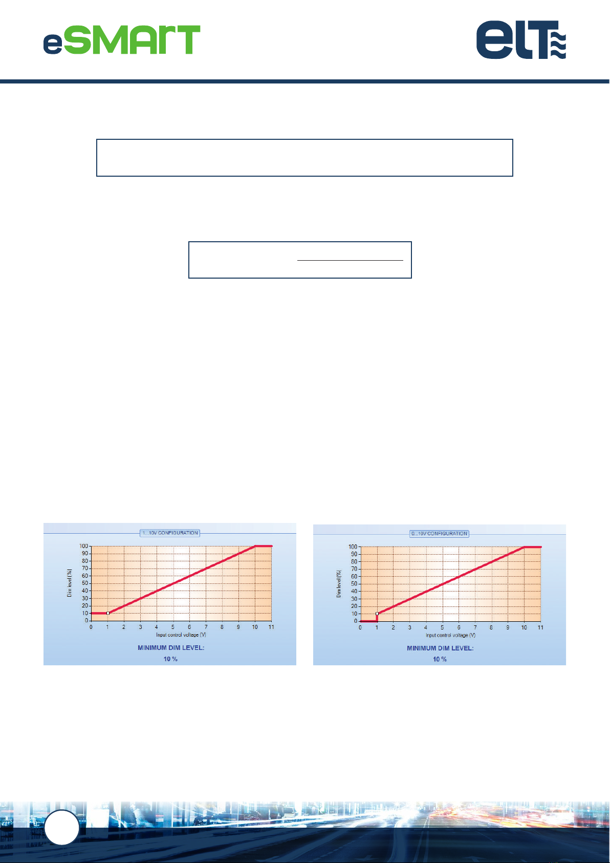
The response of the 1-10V dimming differs slightly to the 0-10V.
In 1-10V dimming, the maximum dimming level is obtained by leaving the control terminals in open circuit or with
a signal equal to 10V. This is the 100% level and cannot be congured. The minimum level, however, is obtained by
short-circuiting the control terminals or via a signal lower than 1V and this may be congured.
0-10V dimming is almost the same as that for 1-10V except that the drivers can enter into standby mode when the
control terminals are short-circuited or with a signal that is very close to 0V. The standby output is guaranteed for
values higher than 1.5V.
Within the temperature ranges at point tc between -40ºC and -30ºC the driver will remain at the maximum level
regardless of the signal in the control terminals. However, the driver will respond to the set points as it enters standby
if the selected dimming mode is 0-10V.
NOTE:
Drivers from different manufacturers may produce different responses to the same control signal value.
No of devices to control x Maximum output current of the 1-10V / 0-10V control terminals
Potentiometer value = 560 k Ω
nº devices in parallel
Example 1-10V and 0-10V dimming curves
19
www.elt.es
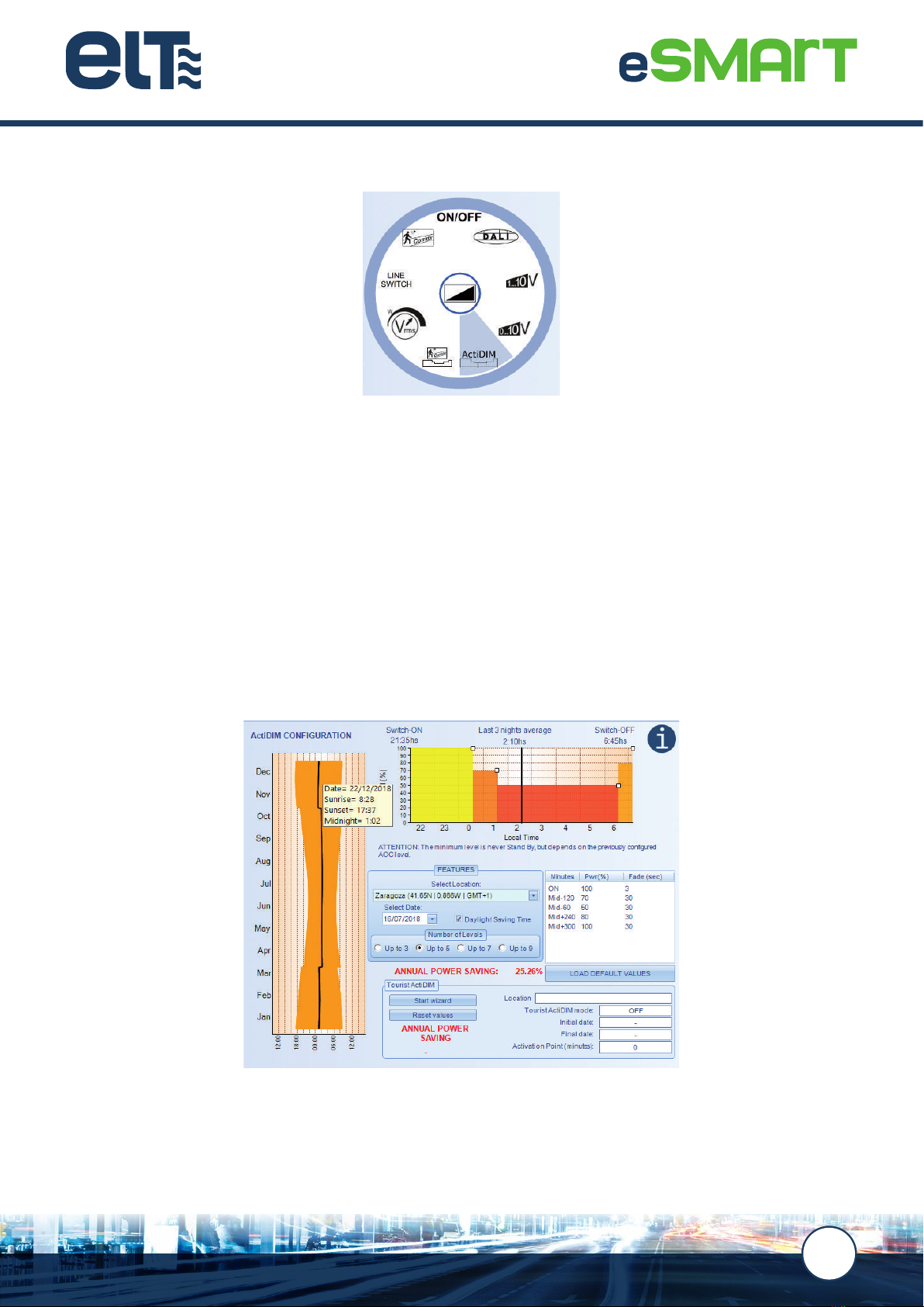
6.3. ActiDIM mode
The ActiDIM operating mode is a stand-alone dimming system that simulates astronomical behaviour to provide
energy saving without the need to wire in a control line.
The automatic dimming algorithm controls the times at which a change of light level has to take place. It takes as
a reference the average night time duration point, calculated based on the average of the last three nights. The
duration of each night is dened as the time measured from when the street lighting is switched on to the time it is
switched off.
NOTE:
When the lighting is switched on for less than 4 hours (for example, to carry out maintenance tasks or during power outages) and in
cases where it is on for more than 20 hours, the control gear does not memorise that period as a ‘night’ and therefore does not take
it into account when applying the ActiDIM calculation algorithm.
This system is able to congure different dimming proles, selecting up to maximum of 9 levels, their value, the
duration of the transitions and the changes between them.

www.elt.es
20
Tourist ActiDIM mode
This option is recommended for situations that require total or partial deactivation of the dimming prole established
by the ActiDIM operating mode during the night over one period of the year, dened on an approximate basis, in a
specic location.
For example, in summer, the initial dimming parameters dened for the period up until midnight are cancelled, so
that the driver operates at maximum power up to that point, before continuing to follow the prole established under
normal ActiDIM mode.
This function offers added value to the standard ActiDIM mode, as it allows the luminaire to operate with two different
behavioural patterns with no need for control cabling to change from one mode to the other.
This manual suits for next models
9
Table of contents
Popular Control Unit manuals by other brands

Becker
Becker S20 MLS Assembly and Operating Constructions

Bitzer
Bitzer CM-RC-01 reference guide

Vaillant
Vaillant FM5 installation instructions

aquabrass
aquabrass SR3095 installation guide

Allen-Bradley
Allen-Bradley FLEX I/O 1794-OB8 installation instructions

Lantronix
Lantronix TN-SFP 25G R-S Series user guide


