Eltek GenII RC250 User manual

1
Table Of Contents
1. Introduction................................................................................... 4
2. System principles of operation ....................................................... 5
2.1 Appropriate applications ................................................................... 5
2.2 Transmitter interval............................................................................ 5
3. RC250 Receiver .............................................................................. 6
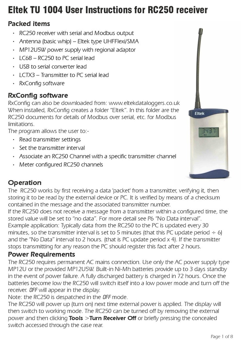
3.1 Packed items ..................................................................................... 6
3.2 RxConfig software............................................................................. 6
3.3 Operation .......................................................................................... 6
3.4 Power Requirements ......................................................................... 6
3.5 Application ........................................................................................ 7
3.6 LED Indicator..................................................................................... 7
3.7 RC250 programming leads ............................................................... 7
3.8 Top panel connections ..................................................................... 8
3.9 Specification ...................................................................................... 8
4. Care and disposal of product......................................................... 9
5. Maintenance and calibration ....................................................... 10
5.1 Maintenance ...................................................................................10
5.2 Calibration .......................................................................................10
6. Note about RF performance......................................................... 11
7. Accessories................................................................................... 12
7.1 Probes and sensors .........................................................................12
7.2 Antenna ..........................................................................................12
7.3 Wall bracket.....................................................................................12
7.4 Leads ...............................................................................................12
7.5 Connectors......................................................................................12
7.6 Weatherproof enclosure .................................................................12
7.7 AC Transducer.................................................................................12
7.8 Power supply...................................................................................12
7.9 Communications module ............................................................... 13
8. Replacement accessories .............................................................. 14
8.1 Antenna ..........................................................................................14
8.2 Battery .............................................................................................14
8.3 Connectors......................................................................................14
8.4 Leads ...............................................................................................14
8.5 TMET ...............................................................................................14
8.6 Power supply...................................................................................15

2
9. Supported third party sensor products ........................................ 16
10. Repeater notes............................................................................. 17
10.1 Power requirements........................................................................17
10.2 Product Specification.......................................................................17
10.3 RSSI indicator (calibrated from serial number 7925 to current) ......21
10.4 Radio coverage survey.....................................................................22
10.5 Preparing the transmitter and repeater for the survey ................... 24
10.6 Carrying out the survey...................................................................24
11. Using the Receiver Config software ............................................. 26
11.1 RxConfig System Requirements ......................................................26
11.2 Channel Set-up Procedure .............................................................. 27
11.3 Columns in the RX Configuration panel table:............................... 28
11.4 Modbus configuration ....................................................................28
11.5 Help file issues.................................................................................32
12. Transmitter connections............................................................... 33
12.1 GS/GD13E .......................................................................................33
12.2 GS/GD14E .......................................................................................33
12.3 GS/GD 31/2/4/4R/8 .........................................................................33
12.4 GD40A.............................................................................................33
12.5 GS41A.............................................................................................. 34
12.6 GS42/42E......................................................................................... 34
12.7 GD43E.............................................................................................35
12.8 GS44/GS44E/GS44H .......................................................................36
12.9 GS44AVE .........................................................................................36
12.10 GS/GD52 ......................................................................................... 37
12.11 GS60 ................................................................................................37
12.12 GC62 ...............................................................................................37
12.13 GC62EX ...........................................................................................37
12.14 GD67 ............................................................................................... 38
12.15 GD68 ............................................................................................... 38
12.16 GD72E............................................................................................. 38
12.17 GD90A/900A...................................................................................38
12.18 GD93A............................................................................................. 38
13. Specifications ............................................................................... 39
13.1 Common transmitter specification .................................................39
13.2 Individual transmitter specifications................................................39
14. Transmitter product revisions....................................................... 43
15. Thermocouple isolation and interference issues .......................... 44

3
16. Pulse count and GenII telemetry .................................................. 45
Declaration of Conformity ................................................................... 46

4
1. Introduction
This manual is for users who have purchased an Eltek GenII system
comprising Eltek standard transmitters, standard repeater(s) and an RC250
receiver together with the RxConfig or software.
It assumes that the application is satisfied using this standard equipment and
that a survey has been conducted to ensure that the radio range covers the
site in question within the required margin of safety of performance.
It assumes that the RxConfig software will be used to configure the RC250
and transmitters and that the RepConf software will be used to set up
repeaters if required.
Quick survey methodology is included.
Eltek has made all user instructions, manuals, data sheets and technical notes
available on their website at www.eltekdataloggers.co.uk/support.html.
Details of specific links are provided where applicable and any relevant
information is also reprinted in this manual to assist the user.
A section is included for standard accessories, identifications and use. A
limited number of standard readily available probes and sensors are covered.
07-06-16

5
2. System principles of operation
2.1 Appropriate applications
The Eltek GenII wireless telemetry system is ideal for a wide variety of
applications that involve the accurate monitoring of data in conditions where
events are slow moving.
Therefore, the system works well in applications such as measuring the
environment in a building or following a process. However, the system cannot
accurately record values that change very quickly. (<500mS)
2.2 Transmitter interval
The GenII system is a one way telemetry system. There is no need for a
receiving or polling device at the transmitter unit, meaning battery endurance
can be several years using off the shelf batteries.
Transmitters send the sensor value(s) or averaged (transmitter dependant)
sensor values at a random point in time within the configurable transmitter
interval.
The receiver is continuously active. The random transmissions from the various
transmitters are held in a pending value register that is successively updated
as newer, valid transmissions are received.

6
3. RC250 Receiver
3.1 Packed items
•RC250 receiver with serial and Modbus output (RS232)
•Antenna (basic whip) –Eltek type UHFFlexi/SMA
•MP12U power supply with regional adaptor
•LC68 –RC250 to PC serial lead
•USB to serial converter lead
•LCTX3 –Transmitter to PC serial lead
•RxConfig software
•Optional RS485 adapter (must be ordered with RC250 –see
accessories.)
3.2 RxConfig software
RxConfig can also be downloaded from: www.eltekdataloggers.co.uk
When installed, RxConfig creates a folder “Eltek”. In this folder are the RC250
documents for details of Modbus over serial, etc. for Modbus limitations.
The program allows the user to:-
•Read transmitter settings
•Set the transmitter interval
•Associate an RC250 Channel with a specific transmitter channel
•Meter configured RC250 channels
3.3 Operation
The RC250 works by first receiving a data 'packet' from a transmitter, verifying
it, then storing it to be read by the external device or PC. It is verified by means
of a checksum contained in the message and the associated transmitter
number.
If the RC250 does not receive a message from a transmitter within a
configured time, the stored value will be set to “no data”. For more detail see
“No Data interval” on page 8 (Section 11).
Example application: Typically data from the RC250 to the PC is updated every
30 minutes, so the transmitter interval is set to 5 minutes (that this PC update
period ÷ 6) and the “No Data” interval to 2 hours. (that is PC update period x
4). If the transmitter stops transmitting for any reason the PC should register
this fact after 2 hours.
3.4 Power Requirements
The RC250 requires permanent AC mains connection. Use only the AC power
supply type MP12U provided. Built-in Ni-Mh batteries provide up to 3 days
standby in the event of power failure. A fully discharged battery is charged in

7
72 hours. Once the batteries become low the RC250 will switch itself into a
low power mode and turn off the receiver. OFF will appear in the display.
Note: the RC250 is despatched in the OFF mode.
The RC250 will power up (turn on) next time external power is applied. The
display will then switch to working mode. The RC250 can be turned off by
removing the external power and then clicking Tools >Turn Receiver Off or
briefly pressing the concealed switch accessed through the case rear.
3.5 Application
For users who wish to use the Eltek GenII series of transmitters with third
party or proprietary software. The RC250 can also be used to interface GenII
transmitters to:
•Existing data acquisition systems such as the Datataker DT80 (using
Modbus)
•BMS (e.g. Trend) via a Synapsis interface or Trend IQ3 (using Modbus)
3.6 LED Indicator
A red LED on the top of the RC250 Indicates the receiver has successfully
received a valid data packet. (In addition to this, the RC250 display will show
the serial number of the transmitter received and the RSSI will show the signal
strength.)
3.7 RC250 programming leads
LC68 –used to program the RC250 from the PC serial port or via the USB
adaptor if no serial port is available
LCTX3 –used to program the Transmitter from the PC serial port or via the
USB adaptor if no serial port is available
A single serial port on the PC can be used but this will mean having to change
over the LCTX3 lead and LC68 as required. Note, in File > Properties the PC
com port can be nominated. You can use the Device Manager in Windows to
list the COM ports available on your computer. Type Device Manager in the
Windows search box to open this, and look for Ports. USB to serial converters
supplied by Eltek are listed as Prolific USB-to-serial.

8
3.8 Top panel connections
12V DC
regulated
comms
12VDC
(inner is -ve)
Comms
(6 way mini Din)
3.9 Specification
Maximum no. Channels
160
AC supply
100 to 250V AC (Use only Eltek power supply type
MP12U)
DC input
12VDC Maximum current <150mA
Battery endurance
Up to 72 hours
Battery charge time
Trickle - allow 72 hours to fully charge an
exhausted battery.
Controls
Concealed button (power off)
Freq. UHF (Europe)
Default is 434.225Mhz (the label on the base will
give the exact frequency)
Rx sensitivity
-117dbm (typical)
Antenna connection
SMA socket
Antenna –standard
type (supplied)
¼ wave whip (shipped with product) –Eltek
UHFFlexi/SMA
Antenna –lightweight
dipole (optional)
Indoor/outdoor dipole, lead length 5m standard
accessory type LW-ANT/SMA. The maximum
recommended lead length is 10m.
Antenna –compact
Yagi (optional)
Lightweight 3 element Yagi, providing up to 6db
gain supplied with 5m lead and plug.
Temperature Range
-10 to +55ºC
Humidity
95% non condensing
Environment
Indoor use only IP40. A secondary enclosure must
be used for outdoor use
Transmitter types
All in GenII range from serial number 7000
Transmitter Interval
1 second to 4 hours

9
4. Care and disposal of product
Care
Please treat all components with care.
Do not expose the transmitter to any harsh environment where extremes of
temperature, humidity or dust can be experienced.
The transmitter must not be used in any hazardous rated environment.
Do not disassemble the transmitter for any other reason than configuration or
battery replacement. Some transmitter types do have a replaceable fuse
should the battery be reverse connected.
Do not expose the transmitter to water, rain or spillage. It is not waterproof.
For operation in these environments a secondary water/weatherproof
enclosure is required and can be supplied by Eltek
Do not abuse the transmitter by dropping, knocking or violent shaking.
Rough handling could damage the transmitter.
Do not operate the transmitter close to a receiving device –ensure there is a
separation of 20cm.
The transmitter power output is below the directive for devices used in a
medical or hospital environment. For further details contact Eltek.
Disposing of the product
This electronic product is subject to the EU directive 2002/96/EC for Waste
Electrical and Electronic Equipment (WEEE). As such it must not be disposed
at a municipal waste collection point. Please refer to your local regulations for
direction on how to dispose of this product in an environmentally responsible
manner

10
5. Maintenance and calibration
5.1 Maintenance
There is no specific maintenance or adjustment required other inspection of
the battery compartment to ensure no corrosion due to battery leakage is
present and battery replacement when necessary.
Batteries
Most transmitters are supplied with a pack of 4 or 6 low cost AA LR6 primary
cells –that is non rechargeable. These should be replaced when the LCD
battery gauge (if fitted) is flashing. The battery voltage can be interrogated
using RxConfig software but is not available on the ModBus output. Failure
to replace exhausted cells can lead to leakage and corrosion which can
damage the transmitter circuity and enclosure.
Always replace with high quality LR6 batteries e.g. GP®Super. It is good
practice to replace the battery cassette or holder, this is available at low cost
from Eltek direct or an authorised distributor.
Mandatory battery change at the time of calibration can be cost effective.
The battery chemistry for devices that are AC powered with built in back-up
batteries (e.g. RX250AL, GD47, GW47 and RP250GD) is NiMh and should be
reliable for many years. It is suggested that they are replaced after 5 years.
5.2 Calibration
Calibration of your wireless telemetric system is essential to maintain accurate
and reliable readings. We recommend annual on-site calibration of RH,
temperature, Lux, and UV. Equipment can be returned to an accredited Eltek
distributor or direct to Eltek for transmitters with built in CO2 sensors.
Transmitters that include RH and temperature are best calibrated using the
sensor exchange procedure. Calibrated digital RH and temp sensors are plug-
in. The original sensor should then be disposed of responsibly or returned to
UK for safe disposal. Alternatively Eltek can test the returned sensor and issue
a report for your audit purposes. This service is chargeable.
Transmitters with Lux or Lux and UV sensors are digital devices and can be
checked against a known light source and calibrated meter. Alternatively they
can be returned to Eltek for calibration. There is a charge for this service.

11
6. Note about RF performance
6.1.1 Improving Reception
Radio waves travel best in open unobstructed spaces. Aerials work best high
up in open spaces. Unfortunately, it is rarely possible to have both of these
criteria met! However these two statements should be kept in mind when
installing the radio system. This will lead to the best performance of the
system that can be obtained in a given situation. Note that metal objects,
thick and damp walls significantly attenuate radio signals. Reinforced concrete
is a real signal killer as it can act like a metal screen.
If a nearby source of interference contains frequency components in the band
of the system, then the receiver will be desensitised. This is especially true if
the interference is stronger than the signal from a distant transmitter. Typical
sources of interference are mobile phones, walkie-talkie type radios, Tetra
police communication systems, computer equipment (especially older
equipment) and anything with a radio transmitter in it, e.g. the components
of a wireless security system.
6.1.2 Locating the Transmitters
Try to place the transmitter as high up as possible, but not too close to
ceilings. Keep away from damp or metal clad walls, metal objects, cabling,
pipes, etc. Also bear in mind that the fewer obstacles in the path to the
receiver will give the greater range and reliability of the system.
6.1.3 Locating the RC250
The RC250 is a single unit that acts as a data receiver. Locate the RC250
central to the transmitters and clear of sources of radio interference.
Where range is not a problem the built in antenna supplied should be used
and provides a very compact installation. Range can be very significantly
improved using the optional LW-ANT/sma dipole or UHFFlexi/Mag/SMA
antenna. This should be mounted as high as possible and away from sources
of interference.

12
7. Accessories
7.1 Probes and sensors
Eltek RH and T detachable probe with
3m lead. (For longer lead refer to Eltek)
RHT10E
Leak sensing cable with 15m inactive
section and 4m active section (other
combinations POA) for GC60F
LC-Leak15/4
7.2 Antenna
Lightweight indoor/outdoor dipole antenna with 5m
lead, SMA plug and mounting hardware
LW-ANT/SMA
5m coaxial antenna extension lead SMA to SMA
ANT-EXT/SMA5m
¼ antenna on magnetic base with 1.8m lead
UHFFlexi/Mag/SMA
7.3 Wall bracket
Tamper-resistant wall bracket for all GenII product (except
TMET)
WBG
7.4 Leads
Serial to USB convertor lead
RS232/USB
2M LC68 lead extender
RS232/2M
7.5 Connectors
Mini thermocouple connector type T (brown)
MiniT
Mini thermocouple connector type K (green)
MiniK
7.6 Weatherproof enclosure
Rugged outdoor (IP65) enclosure with built-in cradle for
most transmitter types.
specify transmitter type and accessories
required with order - if in doubt contact Eltek
OD1 series
7.7 AC Transducer
AC100/240 transducer - provides an isolated contact closure when
powered. Detects presence of an AC supply (can be used to assert
alarms). Use with GD24 or GD34
EL-CC
7.8 Power supply
100-250VAC to 12VDC 7.2W power supply. Specify mains
plug type with order (UK/Euro/US)
MP12U

13
100-250VAC to 9VDC approx.10W supply. Specify mains
plug type with order (UK/Euro)
MP9U
DIN rail mounting AC to 12VDC power supply for GD90A
DRA18-12
Wire-in 24/12V to 9V regulator
24REG9
7.9 Communications module
RS485 interface (for RC250 units after serial no. 25194)
SQ/RS485
"Wired socket" is the mini Phoenix with cage screw terminals or equivalent
with strain relief

14
8. Replacement accessories
8.1 Antenna
Stubby antenna for transmitters 434.225Mhz L=66mm
UHFStub/SMA
Flexi antenna for receiver, repeater or transmitters
434.225Mhz L= 165mm
UHFFlexi/SMA
Flexi antenna on magnetic base with 2M lead with sma
connector
UHFFlexi/Mag/SMA
8.2 Battery
Battery carrier (4 x AA cells not included)
BATCARR4
Battery carrier (6 x AA cells not included)
BATCARR6
Plug-in rechargeable 7.2V MiMh pack for RP250GD,
RC250 or GD47
EL7.2NIMH
6 x 1.8Ah batteries for RC250, RC250D or WSR
EL6XMIMH
8.3 Connectors
2 way transmitter connector - screw down - green with
strain relief
MINIPL2
4 way transmitter connector - screw down - green with
strain relief
MINIPL4
5 way transmitter connector - screw down - green
MINIPL5
6 way transmitter connector - screw down - green
MINIPL6
8 way transmitter connector - screw down - green
MINIPL8
TiniQG - for GD11 temperature probe
QGMX-1320
8.4 Leads
TX set up from PC lead
LCTX3
Receiver to PC serial lead (1.0m) or replacement lead
assembly for MoxaD-311
LC68
8.5 TMET
IP65 outdoor enclosure with pole mount bracket for use
with TMET only
WBT
Pole mounting bracket Skye or Kipp and Zonen
pyranometers
PyrBkt

15
8.6 Power supply
AC to 12VDC power supply (For GD40A)
MP12U/GD40A

16
9. Supported third party sensor products
Type
Manufacturer
Product name
Eltek Product
AC current
transducer (AC
output)
Northern
Design
SCL / SCT
GD90A,
GD900A, 651
Squirrel
AC current
transducer (DC
output)
Northern
Design
SXD
GD40A
Energy meter
Northern
Design
NDRail310,
NDRail350
GD90A,
GD900A, 651
Squirrel
Energy monitor with
pulse output
Rayleigh
PRO1D
GC62, GD67
and GD68
Energy monitor with
pulse output
Rayleigh
PRO75D
GC62, GD67
and GD68
Energy monitor with
pulse output
Elster
A100C
GC62, GD67
and GD68
Heat meter
Landis & Gyr
T230
GD93A
Heat meter
Sontex
SuperCal 539
GC62, GD67
and GD68
Heat meter
Sontex
SuperStatic 440
GC62, GD67
and GD68
Heat flux sensor
Hukseflux
HFP01
GS44H, 451L
Sunshine
pyranometer
Kipp and Zonen
CMP3
GS41Acf, TMET
Sunshine
pyranometer
Skye
Instruments
SKS 1110
GS41Acf, TMET
Water flow meter
Flownetix
Flownetix 315
GC62, GD67
and GD68
Water flow meter
Flownetix
Flownetix 325
GC62, GD67
and GD68
Air velocity
E plus E
EE576/EE660
GS41AV
Carbon dioxide
sensor (0-5/10/20%)
Vaisala
GMT221
GD43E
Weather sensor
Vaisala
WXT520
TMET Weather
Wind sensor
Vaisala
WMT52
TMET Weather
People counter

17
10. Repeater notes
The RP250GD repeater is a self-contained mains operated data packet (GenII
protocol only) repeater.
The RP250GDS repeater additionally includes a built-in switchable loudspeaker
for survey applications.
RP250GD Repeater features:
•An LCD to view activity and status of transmitters in operation
•Received Signal Strength Indication (RSSi) of incoming transmitter data
(chevron bar)
Using the RepConf, Repeater Configuration software you can:
•Authorise transmitters you want to be repeated
•Compensate for systems requiring multiple repeaters
•Conduct a radio survey
10.1 Power requirements
The repeater requires permanent AC mains connection. Use only the AC
power supply provided. When powered the red LED on the top of the unit will
flash. Built-in Ni-Mh batteries provide up to 3 days standby in the event of
power failure. A fully discharged battery is normally charged in 72 hours.
•When you first receive the RP250GD the display will read OFF
•The display will switch to working mode when the MP12U power supply
is connected or by activating the concealed switch if the batteries are
suitably charged.
•If you remove the MP12U power supply the unit will stay in working
mode until the internal rechargeable batteries are exhausted. The display
will then read OFF.
The repeater can be turned off by removing the MP12U power supply and
activating the concealed switch under the small hole on the back of the unit
using an unfurled paper clip or narrow screwdriver. The red LED will stop
flashing and the display will read OFF.
10.2 Product Specification
AC supply:
100 to 250V AC (Use only Eltek power supply type
MP12U)
DC input:
12.5VDC Maximum current <70mA
Battery endurance:
typically 72 hours

18
Freq. UHF (Europe):
default is 434.225Mhz (other frequencies available –
refer to Eltek)
Freq. US:
default is 914.5Mhz (other frequencies available –
refer to Eltek)
Rx sensitivity:
-117dbm (one chevron on signal strength bar)
Tx RF power:
10mW
Antenna connection:
SMA socket
Antenna - standard:
¼ wave whip (shipped with product)
Antenna - alternative:
Indoor/outdoor dipole, lead length 5M standard,
accessory from Eltek Ltd type LW-ANT/sma. The
maximum recommended lead length is 10M.
Transmitter spec:
to European spec EN300-200
Temperature Range:
-10 to +55ºC
Humidity:
95% non-condensing
Environment:
Indoor use only IP40. A secondary enclosure must be
used for outdoor use
Backup batteries type:
Ni MH pack
Backup battery life:
Typically 24 to 48 hours dependant on activity
Dimensions:
D 41mm x W 80mm x H 125mm
Weight:
500g inc. batteries
Receiver/Transmitter:
Crystal controlled
Connectors
DC supply: 2.1mm concentric jack (male)
Comms (serial):
3.5mm stereo jack (applicable up to serial number 8480) –use with lead type
LCTX3
6 pin mini din (applicable to serial number 8481 to current) –use with lead
type LC68
For the latest detailed RP250GD information see the document TU1007 –
RP250GD user instructions (available online).

19
10.2.1 Basic system where there is one RP250GD only
Do not repeat transmitters unnecessarily!
RC250
Repeater #1
Delay = 0
Tx 1002
Tx 1001
10.2.2 A system where are there are two or more RP250GD
Do not repeat transmitters unnecessarily!
Repeater #1
Delay = 0
Tx 1002
Tx 1001
Repeater #2
Delay = 0
RC250

20
10.2.3 For a system where multiple (tandem and radial pattern)
RP250GD used:
Do not repeat transmitters unnecessarily!
Tx 1001
Tx 1002*
Tx 1003
Tx 1004
Repeater #2
Delay = 0
Repeater #3
Delay = 1
Repeater #1
Delay = 0
RC250
•Tip: Make a proposed system schematic as this will assist set up for
the various repeaters in the system.
•*TX1002 could be roving (mobile) around an area of coverage e.g
monitoring a pallet on a fork lift truck, such that Repeater 2 or
Repeater 3 would repeat its transmission.
Table of contents
Other Eltek Receiver manuals
