ELTEX R130A User manual

Operating Instructions
R130A / R131A Charging Bar
EXR130A Charging Bar
BA-en-3020-2101
F01039y

2BA-en-3020-2101_R130A / R130A3L / R131A / EXR130A / EXR130A3L

BA-en-3020-2101_R130A / R130A3L / R131A / EXR130A / EXR130A3L 3
List of Contents
1 Overview charging bars. . . . . . . . . . . . . . . . . . . . . . . . . . . . . . . . 6
1.1 R130A / R131A / EXR130A charging bars . . . . . . . . . . . . . . . . . . . . 6
1.2 R130A3L / EXR130A3L charging bars . . . . . . . . . . . . . . . . . . . . . . . 7
2 Safety. . . . . . . . . . . . . . . . . . . . . . . . . . . . . . . . . . . . . . . . . . . . . . . . 8
2.1 Proper use . . . . . . . . . . . . . . . . . . . . . . . . . . . . . . . . . . . . . . . . . . . . 8
2.2 Identification of risks and hazards . . . . . . . . . . . . . . . . . . . . . . . . . 8
2.3 Work and operational safety. . . . . . . . . . . . . . . . . . . . . . . . . . . . . . 9
2.4 Contact protection . . . . . . . . . . . . . . . . . . . . . . . . . . . . . . . . . . . . . 11
2.5 Inspection of the protective resistors - contact protection . . . . . . . 11
2.6 Technical advance . . . . . . . . . . . . . . . . . . . . . . . . . . . . . . . . . . . . 11
3 Installation and assembly . . . . . . . . . . . . . . . . . . . . . . . . . . . . . 12
3.1 Length of the charging bar . . . . . . . . . . . . . . . . . . . . . . . . . . . . . . 12
3.2 Length of the high voltage cable. . . . . . . . . . . . . . . . . . . . . . . . . . 12
3.3 Adjust the angle coupling . . . . . . . . . . . . . . . . . . . . . . . . . . . . . . . 12
3.4 Installation of the charging bar . . . . . . . . . . . . . . . . . . . . . . . . . . . 12
3.5 Connecting the high voltage cable to the generators KNH18,
KNH34 / KNH35, KNH64 / KNH65, to the distributor box
KNHV3 / KNHV6 and to the charging bar R131A. . . . . . . . . . . . . . 17
3.6 Connecting the high voltage cable of the charging bar to the
high voltage generator POWER CHARGER PC_ _ . . . . . . . . . . . . 18
3.7 Disconnecting the high voltage cable . . . . . . . . . . . . . . . . . . . . . . 19
4 Operation. . . . . . . . . . . . . . . . . . . . . . . . . . . . . . . . . . . . . . . . . . . 20
4.1 Operating voltage for the R130A / R130A3L / R131A /
EXR130A / EXR130A3L charging bars . . . . . . . . . . . . . . . . . . . . 20
4.2 Operating modes . . . . . . . . . . . . . . . . . . . . . . . . . . . . . . . . . . . . . 20
5 Maintenance . . . . . . . . . . . . . . . . . . . . . . . . . . . . . . . . . . . . . . . . 21
6 Warranty . . . . . . . . . . . . . . . . . . . . . . . . . . . . . . . . . . . . . . . . . . . 22
7 Troubleshooting . . . . . . . . . . . . . . . . . . . . . . . . . . . . . . . . . . . . . 23
8 Technical specifications . . . . . . . . . . . . . . . . . . . . . . . . . . . . . . 24
9 Dimensions . . . . . . . . . . . . . . . . . . . . . . . . . . . . . . . . . . . . . . . . . 26
10 Spare parts and accessories. . . . . . . . . . . . . . . . . . . . . . . . . . . 27
A ANNEX . . . . . . . . . . . . . . . . . . . . . . . . . . . . . . . . . . . . . . . . . . . . . 29
A.2 Quick plug-in connection for charging components for plug
variants M . . . . . . . . . . . . . . . . . . . . . . . . . . . . . . . . . . . . . . . . . . . 29
Declaration of Conformity . . . . . . . . . . . . . . . . . . . . . . . . . . . . . . . . . . 30

4BA-en-3020-2101_R130A / R130A3L / R131A / EXR130A / EXR130A3L

BA-en-3020-2101_R130A / R130A3L / R131A / EXR130A / EXR130A3L 5
Dear customer
The R130A / R130A3L / R131A / EXR130A / EXR130A3L charging bar is
a universal bar for charging surfaces for the purpose of tacking, adhering
or locking. The variable active lengths of the charging bars allow them to
be adapted to your specific in-process conditions and requirements.
The charging bar is mainly used where production processes and cycles
run faster and with less interference if the materials used (such as films,
foils, papers, etc.) adhere to each other.
The charging bar EXR130A / EXR130A3L is available for use in the Ex
zone.
The bars are operated with the appropriate high voltage generators sup-
plied by Eltex. These can be adjusted to match the different active lengths
of the bars and so allow optimized operation.
Please read these instructions carefully before starting the unit. This will
help you prevent personal injuries and damage to property.
Simply give us a call if you have any suggestions, proposals or ideas for
improvements. We greatly appreciate the feedback from the users of our
appliances.

6BA-en-3020-2101_R130A / R130A3L / R131A / EXR130A / EXR130A3L
1. Overview charging bars
The variety of charging bars available differs essentially in their installation
lengths and in their connection of the high voltage cable. Both the installa-
tion length and the variable active length of a charging bar allow the units
to be adapted to the most varied applications.
The parallel configuration of two or more bars allows surface-covering
charging or operating the unit at high web speeds.
The maximum total length of the charging bar is 3985 mm.
1.1 R130A / R131A / EXR130A charging bars
Fig. 1:
R130A / R131A /
EXR130A
charging bars
Z00064y
X
Kabel nicht lösbar
cable non-detachable
câble de haute tension moulé
Kab
cabl
câble
Kabel nicht lösbar
cable non-detachable
câble de haute tension moulé
0...360° (max. 1 revolution)
View X

BA-en-3020-2101_R130A / R130A3L / R131A / EXR130A / EXR130A3L 7
R130A / EXR130A bar
The connection of the high voltage cable can be axial or at a right angle to
the bar.
R131A bar
The connection of the high voltage cable is detachable and only available
axial to the bar.
1.2 R130A3L / EXR130A3L charging bars
R130A3L / EXR130A3L bar
Same bar as R130A / EXR130A,but with air connection.
Fig. 2:
R130A3L /
EXR130A3L
charging bars
Z-111886by

8BA-en-3020-2101_R130A / R130A3L / R131A / EXR130A / EXR130A3L
2. Safety
The units have been designed, built and tested using state-of-the-art engi-
neering, and have left the factory in a technically and operationally safe
condition. If used improperly, the units may nevertheless be hazardous to
personnel and may cause injury or damage. Read the operating instruc-
tions carefully and observe the safety instructions.
2.1 Proper Use
The charging bars of the series R130A / R130A3L / R131A / EXR130A /
EXR130A3L must only be used for applying static electrical charges onto
paper, fabrics, foils, plastics, etc. for the purpose of creating a static adhe-
sion effect.
The R130A / R130A3L / R131A / EXR130A / EXR130A3L charging bars
may only be operated with the accompanying Eltex high voltage genera-
tors (see Chapter 8 "Technical specifications"). These allow the flexible
adaptation to the required high voltages and currents for different active
bar lengths. The safe operation of the charging bars is only guaranteed by
using these Eltex generators.
Caution!
When using the EXR130A / EXR130A3L charging bar, please note the
operating instructions for the appropriate system and/or generator.
The manufacturers will not assume any liability and warranty if the units
are used improperly or used outside the intended purpose.
Modifications or changes made to the devices are not permitted.
Use only original Eltex spare parts and equipment.
2.2 Identification of risks and hazards
Possible risks and hazards resulting from the use of the units are referred
to in these operating instructions by the following symbols:
Warning!
This symbol appearing in the operating instructions refers to operations
which, if carried out improperly, may result in serious personal injuries.
Caution!
This symbol appearing in the operating instructions refers to operations
which, if carried out improperly, may result in damage to property.
Ex Warning!
For units with EX approval only.
This symbol denotes the special conditions which must be observed when
operating the system in explosion hazard areas as specified in the EX
approvals.
Ex!

BA-en-3020-2101_R130A / R130A3L / R131A / EXR130A / EXR130A3L 9
2.3 Work and operational safety
Warning!
Electric shock hazard!
Carefully observe the following notes and the complete chapter 2 "Safety”,
page 8!
• Before carrying out repairs, cleaning or maintenance work and before
resetting the unit after malfunctions, switch off the power supply and
disconnect the supply voltage (see chapter 5 "Maintenance”, page 21,
chapter 7 "Troubleshooting”, page 23).
• Before carrying out any work involving the units, the machine which has
the units fitted must not be in operation (see chapter 5 "Maintenance”,
page 21, chapter 7 "Troubleshooting”, page 23).
• Any work involving the units must be carried out by qualified electrici-
ans (see chapter 5 "Maintenance”, page 21, chapter 7 "Troubleshoo-
ting”, page 23).
• The unit may only be used by qualified personnel trained for explosion
hazard areas.
• The bars passively absorb energy from the moving substrate web. The
high voltage cable must be plugged in or grounded to the power supply.
If the high voltage cable is disconnected, the plug is live (high voltage)
and applies with full power on the plug; this may cause a spark dis-
charge and may lead to a risk of injury. Disconnected high voltage plugs
are not permitted or have to be grounded (see chapter 5 "Mainte-
nance”, page 21).
• Install the bar such that no creepage currents develop through the bars
and the attachment fittings during subsequent operation. Observe mini-
mum installation distances and the bold depth (see chapter 3.4 "Instal-
lation of the charging bar”, page 13).
• The charging bars must be installed in dry ambient air to prevent con-
densation from settling on the surface of the charging bars (see chapter
3.4 "Installation of the charging bar”, page 13).
• In applications with movable charging bar (e.g. film draw strips), attach
the high voltage cables such that there is no cable movement in the
connecting zone of the power supply (see chapter 3.4 "Installation of
the charging bar”, page 13).
• The high voltage cable must be pushed up to the stop (90 mm for
KNH18 / KNH35 and 120 mm for KNH65) into the cable inlet! The con-
necting area of the high voltage cable must be kept clean (see chapter
3.5 "Connecting the high voltage cable to the generators KNH18,
KNH34 / KNH35, KNH64 / KNH65, to the distributor box KNHV3 /
KNHV6 and to the charging bar R131A”, page 17).
• The high voltage cable must be pushed up to the stop (150 mm) into
the cable inlet! The connecting area of the high voltage cable must be

10 BA-en-3020-2101_R130A / R130A3L / R131A / EXR130A / EXR130A3L
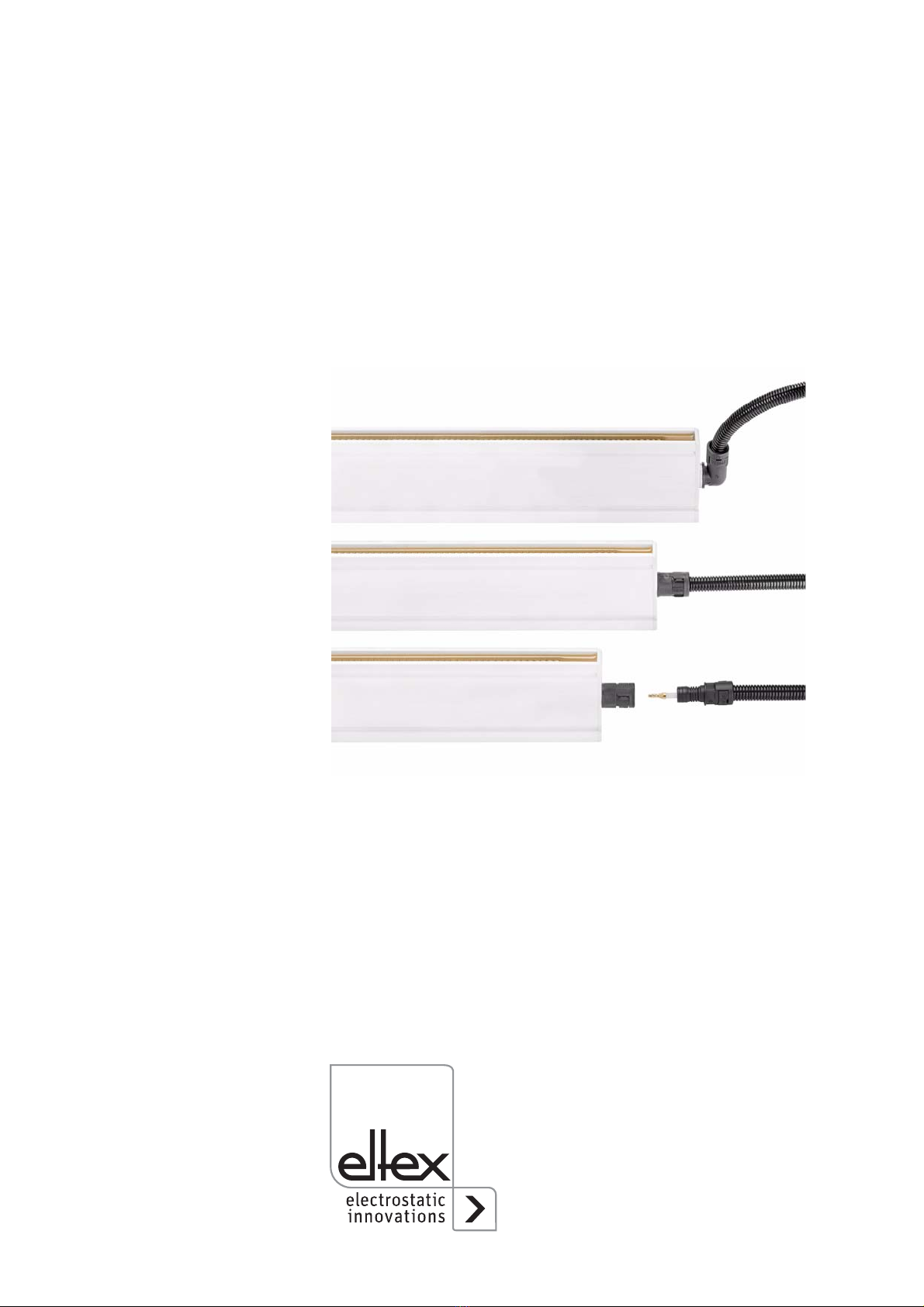
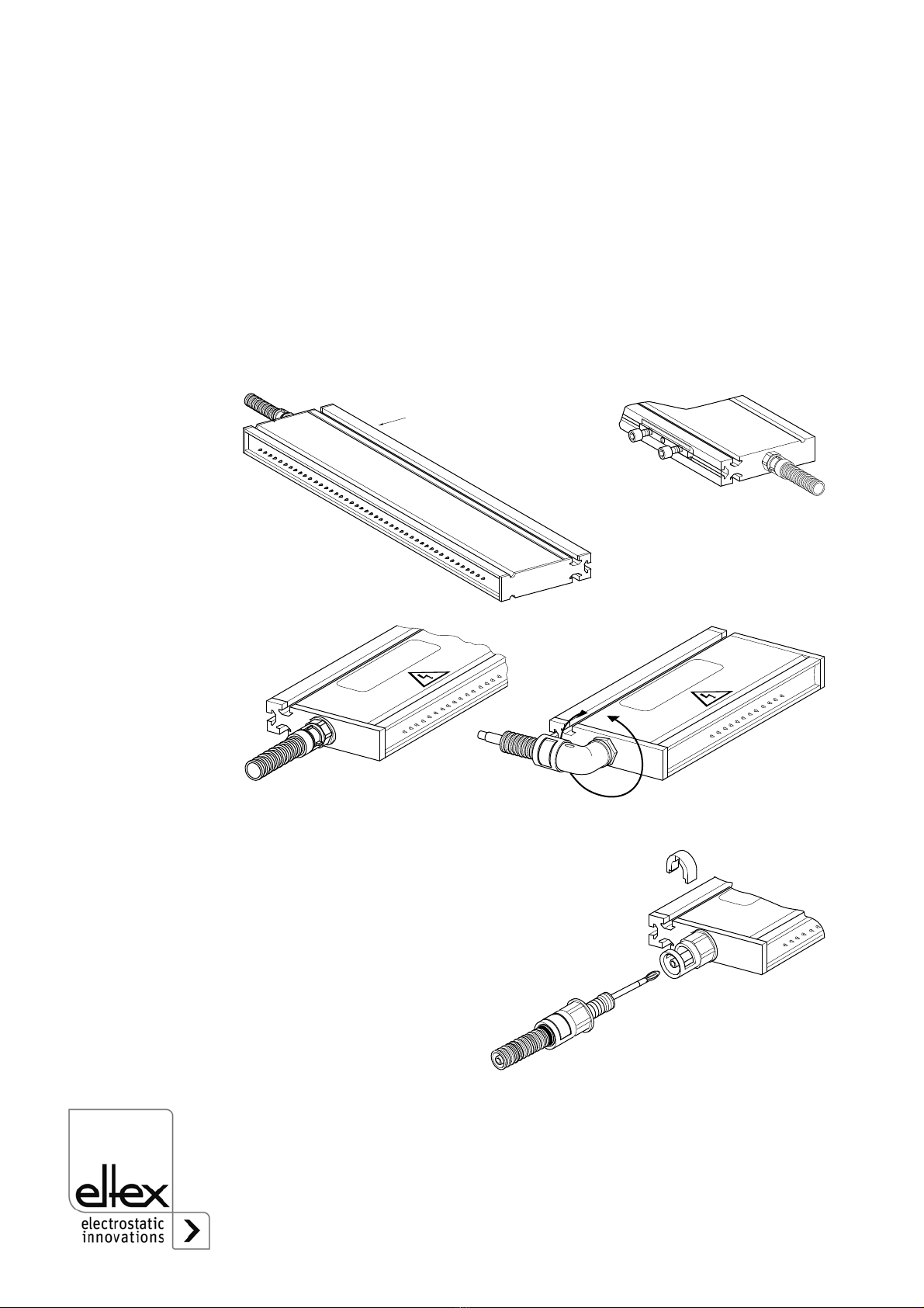
kept clean (see chapter 3.6 "Connecting the high voltage cable of the
charging bar to the high voltage generator POWER CHARGER PC_ _”,
page 18).
• The operating voltages of the charging bars are different. Make sure
that the correct distance between the charging bar and the material sur-
face is maintained (see chapter 4 "Operation”, page 20).
• The current must not be allowed to exceed 1 mA per meter of active
charging bar length. The minimum operating current for any stable-cur-
rent working point must be >0.5 mA (see chapter 4.1 "Operating voltage
for the R130A / R130A3L / R131A / EXR130A / EXR130A3L charging
bars”, page 20, chapter 4.2 "Operating modes”, page 20).
• When cleaning the bars do not soak the bars and the high voltage cable
in solvent and do not damage the emission tips; allow the solvent to
evaporate completely before restarting the unit. No continuous sparking
(electric arc) must be visible on the bar tips (see chapter 5 "Mainte-
nance”, page 21).
• Check the units and the high voltage cables at regular intervals and
before startup for any damage. Any damaged components must be
repaired or replaced professionally before continuing to operate the
unit, or the units must be disabled.
• Make sure that the units are clean at all times.
Dirt results in malfunctions and in premature wear of the units.
• Do not touch the emission tips - risk of injury.
If the high voltage supply is connected, reflex responses to electrical irri-
tation can lead to secondary accidents; the charging bar as such is safe
to touch. If contact is made, the energy transferred is so low
(≤ 20 tips) that there is no risk of injury.
• Potential dangers for persons with cardiac pacemakers
The contact of several emission tips with the hand can trigger or sup-
press a single impulse. Such a single influence is irrelevant. A repeated
contact during a short period can be excluded because the electrical irri-
tation causes a warning effect. The charging bar as such is safe to
touch. If contact is made, the energy transferred is so low that there is
no risk of injury.
• If electrically conductive substrates or substrates coated with conduc-
tive material (e.g. metal foil or metal composites) are used (e. g. in the
printing process), the charging voltage must be disabled (in these prin-
ting units), if applicable the supply voltage of the generator must also be
disabled.
• The operation of the bars can generate ozone. The ozone concentration
levels developing near the bars depend on many different factors such
as site of installation, bar current and voltage, air circulation, etc., and
can therefore not be specified in general terms.
If the maximum allowable concentration of ozone must be observed at

BA-en-3020-2101_R130A / R130A3L / R131A / EXR130A / EXR130A3L 11
the site of installation of the bar, the concentration must be measured
on site.
The AGW value (maximum admissible concentration) serves to assess
the ozone concentration at the workplace. The user must make sure
that the appropriate national AGW value is at no times exceeded, e.g.
in Germany the ozone concentration occurring during the operation of
the system must not exceed the recommended value based on interna-
tional limits of 0.06 ml/m³ (0.12 mg/m³).
• Static on personnel
Static charges on personnel are unlikely if the bars are installed pro-
perly. Personnel must wear conductive footwear.
Please note all national regulations regarding electrostatic charge (e.g.
TRGS 727 in Germany).
Caution!
Please observe the safety notices in the operating instructions of the
systems or generator used with the EXR130A / EXR130A3L charging
bar, and the notices on Ex approvals of the EXR130A / EXR1303AL in
the Technical Specifications.
2.4 Contact protection
The site of installation and/or use of the units is outside the control of
Eltex, contact protection against inadvertent contact of the bars and of live
components by personnel as specified by the employer’s liability insu-
rance association may have to be provided (e.g. DGUV V3 in Germany).
Contact protection devices made of conductive material must be
grounded.
2.5 Inspection of the protective resistors - contact protection
The function and the appearance of the protective resistors must be
inspected at regular intervals. The inspection intervals are specified in the
accident prevention regulations, as amended (e.g. in Germany DGUV
V3).
The function of the series resistors must be checked using a suitable
measuring device. The test voltage must be 1,000V. The measured resis-
tance between the high-voltage connection and the individual emission tip
must not fall below 320 MOhm and not exceed 480 MOhm.
2.6 Technical advance
The manufacturer reserves the right to make changes to the technical
specifications without prior notice in order to adapt the units to state-of-
the-art engineering. Eltex will provide the latest information on any
changes or modifications in the operating instructions on request.

12 BA-en-3020-2101_R130A / R130A3L / R131A / EXR130A / EXR130A3L
3. Installation and assembly
3.1 Length of the charging bar
Depending on intended use, the total length of the charging bar may be
selected within the range from 85 mm to 3,985 mm in steps of 20 mm
each. The total length is made up of active length plus 70 mm.
For operating voltages >30 kV add 120 mm or 220 mm instead of 70 mm
(see Fig. 1). Another 100 mm (approx.) must be provided for plugs and
bending radius of the cable.
3.2 Length of the high voltage cable
The standard length of the high voltage cable feeding the charging bar is
5 meters. Special lengths on request. For cable extension use high
voltage distributor box (connection of high voltage plug see Chapter 3.5).
3.3 Adjust the angle coupling
If the bar has a angle coupling, then it is aligned towards the tips during ex
factory delivery.
To turn the angle connection, proceed as follows:
• loosen the lock nut.
• turn the angle coupling in its desired position.
• re-tighten the lock nut.
The maximum permissible angle of turn of the angle coupling is 360°.
Fig. 3:
Angle coupling
1 Lock nut
2 Angle coupling 0…360°(max. 1 revolution)
Z000065
1
2

BA-en-3020-2101_R130A / R130A3L / R131A / EXR130A / EXR130A3L 13
3.4 Installation of the charging bar
Use flame-retardant GRP assembly material (rods and isolators) to attach
the charging bar to the machine. Examples for installation and notes are
given in Fig. 4, Fig. 5 and Fig. 6. The charging bar is bolted to the GRP
holders via sliding nuts pushed into one of the three profile flutings. Nor-
mally, the GRP rod is attached to the machine via a metal angle piece.
The charging bar is attached with the GRP holder to the machine wall.
The GRP holder is bolted with sliding nuts in the fluting of the charging
bar. Any of the three flutings may be used for installation.
Possible applications: Stabilizing material webs, reducing the air gap,
improving heat transfer.
The installation may also be carried out using fitting material supplied by
Eltex. The material consists of two insulators with GRP base plate plus
four sliding nuts with bolts. The insulators maintain the 150 mm creepage
distance.
Order No. for the Eltex assembly kit: BMO08613.
Fig. 4:
Installation
example showing
charging bar with
GRP holder,
charging against
earth (roller)
1GRProd
2Bar
3 Creepage
distance
4 Machine wall
5 High voltage
cable with
protection tube
Z00066y
>200
>150
>150
12
345

14 BA-en-3020-2101_R130A / R130A3L / R131A / EXR130A / EXR130A3L
Possible applications. tacking protective foil, laminating decorative mate-
rial etc.
Fig. 5:
Installation
example using
Eltex fitting
material
1Bar
2 Eltex fitting
material
3 Machine wall
Z00067y
a
>200
1
2
3
Fig. 6:
Installation
example using
Eltex fitting
material,
charging a foil
against earth with
positive high
voltage
Z00068y
a

BA-en-3020-2101_R130A / R130A3L / R131A / EXR130A / EXR130A3L 15
Install the bar such that no creepage currents develop through the bars
and the attachment fittings during subsequent operation. Creepage cur-
rents can cause irreparable damage to the bar and the attachment fittings.
Minimum installation distances:
• No conductive material to be fitted at a distance of 40 mm around the
charging bar
• Maintain a creepage distance of >150 mm between the charging bar
and earth potential.
• High voltage cable to be mounted with a minimum clearance in air of
200 mm before attaching it to the machine wall.
• Depending on intended use, the spacing distance (a) between the
charging bar and the material web may be selected between 8 and
40 mm. The required operating voltage and the operating current are
specified in Chapter 4.
Caution!
The specifications given above apply to a maximum operating voltage of
30 kV for R130A3 / R130A3L / R131A.
For higher voltages (special versions) increase the values:
up to 60 kV with factor 2,
up to 120 kV with factor 4.
Caution!
The charging bars must be installed in dry ambient air to prevent conden-
sation from settling on the surface of the charging bars.

16 BA-en-3020-2101_R130A / R130A3L / R131A / EXR130A / EXR130A3L
The installation profile of the charging bar has 3 flutings. Any of these
three flutings may be used for installation. The sliding nuts are pushed into
these flutings, and the charging bar is bolted to these sliding nuts.
Caution!
Observe the bolt depth!
ACharging bar profile with 3 flutings
BProfil section
Max. bolt depth 6.5 mm
Torque :
• 4 Nm metallic screw and sliding nut
• 0.4 Nm plastic screw and sliding nut
Secure bolts against working loose (e.g. Loctite 243)
CSliding nut
Total length below 1 meter = 2 off
Total length below 2 meters = 3 off
Total length below 3 meters = 4 off
Total length below 4 meters = 5 off
Warning!
In applications with movable charging bar (e.g. film draw strips), attach the
high voltage cables such that there is no cable movement in the connec-
ting zone of the power supply.
Fig. 7:
Assembly details
Z00069y
13
2
7
40
15
7
15
5
M5 (3x)
BA
C

BA-en-3020-2101_R130A / R130A3L / R131A / EXR130A / EXR130A3L 17
3.5 Connecting the high voltage cable to the generators KNH18,
KNH34 / KNH35, KNH64 / KNH65, to the distributor box
KNHV3 / KNHV6 and to the charging bar R131A
The connection of the high voltage cable of the charging bar with max.
25 kV, max, 30 kV and max. 60 kV to the KNH18, KNH34 / KNH35,
KNH64 / KNH65 high voltage generators is described in the operating
instructions of the respective generators.
Warning!
Electric shock hazard!
Work may be carried out only if:
• the supply voltage to the generator has been disconnected,
• the machine is at a standstill because the bars pick up charges if the
material web is running.
Method:
Connect the bars via the prefabricated high voltage cable. Push the high
voltage cables up to the stop into the socket connection. Finally, secure
the adapter inside the socket with the clip provided (see figure).
Cables without adapters have a color-coded marking on the flexible
tubing. This marking must lie flush with the outside edge of the coupling.
Note: The clip must be fully inserted.
Caution!
The high voltage cable must be pushed up to the stop (90 mm for KNH18,
KNH34 / KNH35 and 120 mm for KNH64 / KNH65) into the cable inlet!
The connecting area of the high voltage cable must be kept clean!
Fig. 8:
Connecting the
high voltage cable
Z00178y
Fig. 9:
Inserting the clip correct incorrect
Z00018y

18 BA-en-3020-2101_R130A / R130A3L / R131A / EXR130A / EXR130A3L
3.6 Connecting the high voltage cable of the charging bar to the
high voltage generator POWER CHARGER PC_ _
Warning!
Electric shock hazard!
Work may be carried out only if:
• the supply voltage to the generator has been disconnected,
• the machine is at a standstill because the bars pick up charges if the
material web is running.
Method:
Connect the bars via the prefabricated high voltage cable. Push the high
voltage cables up to the stop into the socket connection. Finally, the crew
connection is tightened.
9 / 9.1 High voltage outputs 10 High voltage cable
9.1 High voltage cable connections with 60 kV
Note:
The screw connection must be fastened with a torque of 3 Nm.
Caution!
The high voltage cable must be pushed up to the stop (150 mm) into the
cable inlet! The connecting area of the high voltage cable must be kept
clean!
Fig. 10:
Connecting the
high voltage cable
Z-116035ay_4
Fig. 11:
Connecting the
high voltage cable
with 60 kV
Z-116035by_7

BA-en-3020-2101_R130A / R130A3L / R131A / EXR130A / EXR130A3L 19
3.7 Disconnecting the high voltage cable
Warning!
Electric shock hazard!
Work may be carried out only if:
• the supply voltage to the generator has been disconnected,
• the machine is at a standstill because the bars pick up charges if the
material web is running.
Take off the clip at the KNH_ _ generators, the KNHV_ distributor boxes
and/or the R131 bar, using a 3 mm screw driver. Then pull out the cable.
Disconnect the union nut (SW18) at the POWER CHARGER PC_ _
generators. Then pull out the cable.

20 BA-en-3020-2101_R130A / R130A3L / R131A / EXR130A / EXR130A3L
4. Operation
4.1 Operating voltage for the R130A / R130A3L / R131A / EXR130A /
EXR130A3L charging bars
R130A, R130A3L, R131A charging bars:
10…30 kV DC
EXR130A, EXR130A3L charging bars:
max. –30 kV DC / +20 kV DC
Make sure that the correct distance between the charging bar and the
material surface is maintained. The distance at an operating voltage of
10 kV is 8...12 mm, and 27...40 mm at 30 kV. The working range is shown
in Fig. 12.
4.2 Operating modes
The charging bars are usually operated with constant voltage, i.e. the high
voltage generated by the generator is non-adjustable. This operating
mode is recommended for all applications in which the material to be
charged has a high intrinsic resistance and where no creepage currents
caused by contamination is expected.
The current must not be allowed to exceed 1 mA per meter of active char-
ging bar length.
If the charging bar is used in applications where strong contamination
must be expected, the operating mode Current Constant ought to be
selected on the generator. This will prevent energy being drawn off in an
uncontrolled manner through creepage currents and damage to charging
bars and installation material.
The minimum operating current for any stable-current working point must
be >0.5 mA.
Fig. 12:
Working range of
the charging bar
asfactorofvoltage
and distance
Z00073y
5 10 15 20 25 30 35 40
30
25
20
15
10
5
0
kV
mm
Example:
The active charging bar length
is 515 mm.
Maximum rated current:
1 mA/metre x 0.515 metre =
0.515 mA
This manual suits for next models
4
Table of contents
Other ELTEX Batteries Charger manuals
Popular Batteries Charger manuals by other brands

Schumacher
Schumacher SC-12000A SpeedCharge owner's manual

Autel
Autel MaxiCharger Quick reference guide

PulseTech
PulseTech XC-QL4-K1 Quick start instruction manual

Schumacher Electric
Schumacher Electric SC1389 owner's manual

Hama
Hama Prima 2/4 operating instructions

Emcotec
Emcotec PowerCharger600 operating instructions