ELTEX TAU-4M.IP User manual

TAU-4M.IP
Operation Manual
Firmware version 2.3.0
VoIP Gateway
IP address: http://192.168.1.1
Username: admin
Password: password
https://eltex-co.com/support/downloads/

____________________________________________________________________________________
____________________________________________________________________________________
2 TAU-4M.IP Subscriber gateway
Document version
Issue data
Revisions
Version 1.2
31.01.2020
Updated according to firmware version 2.3.0
Version 1.1
28.05.2018
Updated according to firmware version 2.1.0
Version 1.0
15.01.2018
First issue
Firmware version
Firmware version: 2.3.0
Web-interface version: 2.3.0.53

____________________________________________________________________________________
____________________________________________________________________________________
TAU-4M.IP Subscriber gateway 3
SYMBOLS
Symbol
Description
Bold font face
Notes, warnings, section headings, titles and table titles are written in bold.
Calibri Italic
Important information is written in Calibri Italic.
NOTES AND WARNINGS
Notes contain important information, tips, or recommendations on device
operation and setup.
Warnings inform users about hazardous conditions which may cause injuries or
device damage and may lead to the device malfunctioning or data loss.

____________________________________________________________________________________
____________________________________________________________________________________
4 TAU-4M.IP Subscriber gateway
TABLE OF CONTENTS
INTRODUCTION ............................................................................................................................................... 6
1 PRODUCT DESCRIPTION ............................................................................................................................. 7
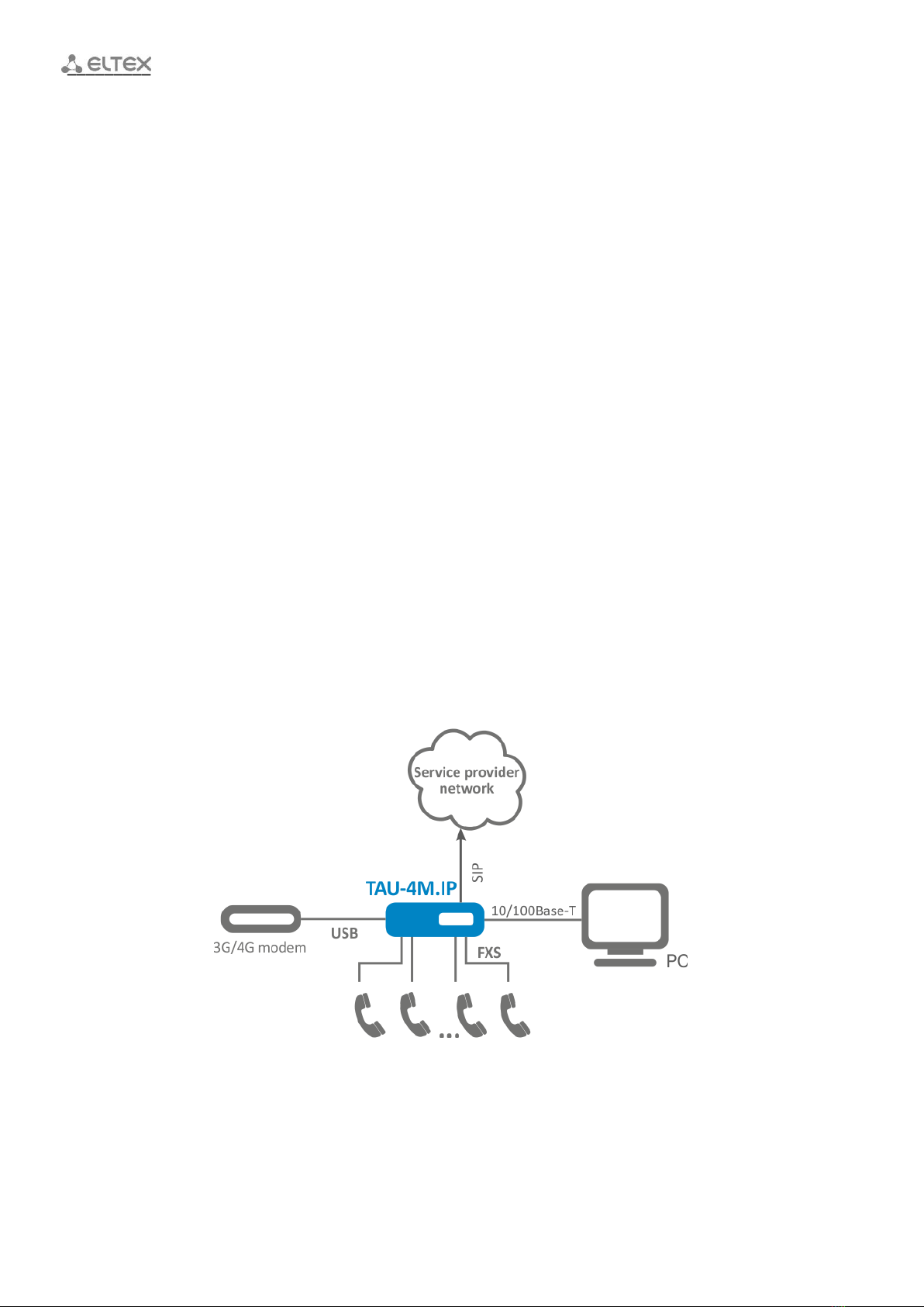
1.1 Purpose............................................................................................................................................... 7
1.2 Device specification............................................................................................................................ 7
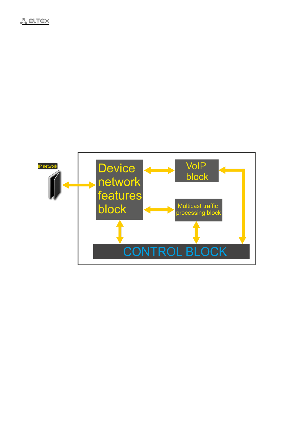
1.3 Device Design and Operating Principle .............................................................................................. 9
1.4 Main Specifications........................................................................................................................... 11
1.5 Design ............................................................................................................................................... 12
1.5.1 Top panel of the device .......................................................................................................... 12
1.5.2 Rear panel of the device ......................................................................................................... 13
1.6 Light indication ................................................................................................................................. 13
1.7 Reset to factory settings................................................................................................................... 14
1.8 Delivery Package............................................................................................................................... 14
2 DEVICE MANAGEMENT VIA WEB CONFIGURATOR..................................................................................15
2.1 Getting started.................................................................................................................................. 15
2.2 Changing users.................................................................................................................................. 15
2.3 WEB interface operation modes ...................................................................................................... 16
2.4 Applying and discarding changes made to configuration ................................................................ 17
2.4.1 Applying configuration............................................................................................................ 17
2.4.2 Discarding changes ................................................................................................................. 17
2.5 ‘Quick configuration’ menu.............................................................................................................. 18
2.5.1 Internet................................................................................................................................... 18
2.5.2 VoIP......................................................................................................................................... 21
2.5.3 IPTV......................................................................................................................................... 22
2.5.4 System..................................................................................................................................... 22
2.6 Advanced settings............................................................................................................................. 23
2.6.1 WEB interface basic elements ................................................................................................ 23
2.6.2 'Network' menu ...................................................................................................................... 23
2.6.3 'VoIP' menu............................................................................................................................. 45
2.6.4 'IPTV' menu............................................................................................................................. 74
2.6.5 'System' menu......................................................................................................................... 75
2.7 System Monitoring ........................................................................................................................... 94
2.7.1 'Internet' submenu ................................................................................................................. 94
2.7.2 'VoIP' submenu ....................................................................................................................... 95
2.7.3 'Ethernet Ports' submenu....................................................................................................... 98
2.7.4 'DHCP' submenu ..................................................................................................................... 99
2.7.5 'ARP' submenu........................................................................................................................ 99
2.7.6 'Device' submenu.................................................................................................................. 100
2.7.7 'CPU' submenu...................................................................................................................... 100
2.7.8 'Conntrack' submenu............................................................................................................ 101
2.7.9 'Routes' submenu ................................................................................................................. 102
2.7.10 'Call History' submenu ....................................................................................................... 103
2.7.11 ‘Diagnostics’ submenu....................................................................................................... 104
2.8 Configuration example ................................................................................................................... 105
3 VALUE ADDED SERVICES USAGE ............................................................................................................108
3.1 Call Transfer.................................................................................................................................... 108
3.2 Call Waiting..................................................................................................................................... 111
3.3 Three-way conference.................................................................................................................... 111
3.3.1 Local conference................................................................................................................... 111
3.3.2 Remote conference .............................................................................................................. 113
4 CONNECTION ESTABLISHMENT ALGORITHMS....................................................................................... 114
4.1 Algorithm of a Successful Call via SIP Protocol............................................................................... 114
4.2 Call Algorithm Involving SIP Proxy Server....................................................................................... 115

____________________________________________________________________________________
____________________________________________________________________________________
TAU-4M.IP Subscriber gateway 5
4.3 Call Algorithm Involving Forwarding Server................................................................................... 116
5 DEVICE AUTOMATIC UPDATE ALGORITHM BASED ON DHCP................................................................ 117
6 SYSTEM RECOVERY AFTER A FIRMWARE UPDATE FAILURE...................................................................120
APPENDIX A. CALCULATION OF PHONE LINE LENGTH ................................................................................121
APPENDIX B. RUNNING USER-DEFINED SCRIPT UPON SYSTEM STARTUP...................................................122
APPENDIX C. DHCP CLIENTS CONFIGURATION IN MULTISERVICE MODE................................................... 123

____________________________________________________________________________________
____________________________________________________________________________________
6 TAU-4M.IP Subscriber gateway
INTRODUCTION
Today, VoIP is one of the most rapidly evolving telecommunication services. TAU-4M.IP series gateways
(hereinafter the "device") are designed to provide VoIP services to the network clients.
TAU-4M.IP VoIP gateway allows connecting analogue phones to packet-based data networks accessible via
Ethernet.
The device is intended for operation in home or small offices (SMB).
This operation manual describes intended use, key specifications, configuration, monitoring, and firmware
update for TAU-4M.IP VoIP gateways.

____________________________________________________________________________________
____________________________________________________________________________________
TAU-4M.IP Subscriber gateway 7
1PRODUCT DESCRIPTION
1.1 Purpose
TAU-4M.IP is a high-performance VoIP gateway with the full set of features that allow users to take
advantage of VoIP functionality.
TAU-4M.IP gateway allows connecting an analogue phone or a fax modem to IP networks. With a built-in
router, the device enables connection of local network equipment to a broadband access network. It is possible
to connect one PC that will be able to access the Internet using integrated NAT/DHCP server features. The USB
port is used to connect external drive, 3G/4G USB modem.
1.2 Device specification
Interfaces:
FXS: 4 x RJ-11 ports
LAN: 1 x Ethernet RJ-45 10/100BASE-T port
WAN: 1 x Ethernet RJ-45 10/100BASE-T port
USB: 1 x USB2.0 port
The gateway is powered via 12V DC adapter for 220V electrical networks.
Functions:
Network functions:
–Operation in ‘bridge’ or ‘router’ mode;
–PPPoE support (PAP, SPAP and CHAP authorization, PPPoE compression);
–PPTP support;
–L2TP support;
–Static IP address and DHCP support (DHCP client on WAN side, DHCP server on LAN side);
–DNS support;
–NAT support;
–Firewall;
–NTP support;
–QoS support (QoS via DSCP and 802.1P);
IPTV function support;
VoIP protocols: SIP;
Echo cancellation (G.168 recommendations);
Voice activity detection (VAD);
Comfort noise generation;
DTMF signals detection and generation;
DTMF transmission (INBAND, rfc2833, SIP INFO);

____________________________________________________________________________________
____________________________________________________________________________________
8 TAU-4M.IP Subscriber gateway
Fax transmission:
–G.711A/G.711U;
–T.38;
Operation w/ and w/o a SIP server;
Value Added Services (VAS):
–Call Hold;
–Call Transfer;
–Call Waiting;
–Call Forward at Busy;
–Call Forward at No answer;
–Call Forward Unconditional;
–DND (Do not disturb);
–Caller ID: FSK, DTMF;
–Hotline;
–Group call;
–Call Pickup;
–Three-way conference call;
–Flexible dial plan;
Firmware update via web interface;
DHCP-based auto provisioning support;
TR-069;
Remote monitoring, configuration and setup: web-interface, Telnet.
Figure1 shows TAU-4M.IP connection diagram.
Figure 1 –TAU- 4M.IP operation diagram

____________________________________________________________________________________
____________________________________________________________________________________
TAU-4M.IP Subscriber gateway 9
1.3 Device Design and Operating Principle
TAU-4M.IP terminal consists of the following subsystems:
Controller that includes:
–Realtek RTL8972C highly-integrated System-on-a-Chip (SoC), including a CPU, 100 Mbit
switch with a built-in PHY, hardware L2/L3/L4 acceleration, USB 2.0 ports, PCI-E controller
and 8 PCM channels for VoIP applications;
–Flash memory –8MВ;
–SDRAM –128МВ.
4 x SLIC subscriber units;
1 x LAN port RJ-45 10/100BASE-T;
WAN Ethernet module: RJ-45 10/100BASE-T;
USB Host port.
Block diagram for the device is shown in Figure2.
Figure 2 –TAU- 4M.IP design diagram
The device runs under Linux operating system. Basic control functions are performed by Realtek processor
which enables IP packet routing, VoIP operation, group traffic proxying and etc.
The device may functionally be divided into four blocks:
Device network features block;
VoIP block;
Multicast traffic processing block;
Control block (Linux operating system).

____________________________________________________________________________________
____________________________________________________________________________________
10 TAU-4M.IP Subscriber gateway
Device network features block enables IP packet transmission and switching according to the device
routing table. Depending on the network interface, this block can process both tagged and untagged packets.
Supports DHCP, PPPoE, PPTP, L2TP.
VoIP block enables SIP protocol operation for transmission of voice signals through the network that
features packet switching. Subscriber’s voice signal is transferred to the SLIC subscriber unit module, where it is
converted into digital form. The digitized signal is transferred to VoIP block to be encoded using one of the
selected standards and is transferred further in the form of digital packets to the controller via the intrasystem
backbone. In addition to voice signals, digital packets contain control and interaction signals.
Multicast traffic processing block enables processing of IGMP messages and multicast traffic for IPTV
functions support.
Control block based on Linux operating system monitors operation of all the other blocks and the device
subsystems and manages their interaction.
Fig 3 shows TAU-4M.IP functional diagram.
Figure 3 –TAU- 4M.IP functional diagram

____________________________________________________________________________________
____________________________________________________________________________________
TAU-4M.IP Subscriber gateway 11
1.4 Main Specifications
Table 1 contains main device specifications.
Table 1 –Main specifications
VoIP protocols
Supported protocols
SIP
Voice codecs
Codecs
G.729, annex A, annex B
G.711а, G.711u,
G.723.1, G.722, G.726-24, G.726-32
Modem transmission: G.711а, G.711u
Fax transmission: G.711а, G.711u, T.38
Ethernet WAN interface specifications:
Number of ports
1
Electrical connector
RJ-45
Data rate, Mbps
10/100, autodetection
Supported standards
BASE-T
Ethernet LAN interface specifications:
Number of interfaces
1
Electrical connector
RJ-45
Data rate, Mbps
10/100, autodetection
Supported standards
BASE-T
Analogue user port specifications
Number of ports
4
Loop resistance (phone resistance excluded)
up to 800 Ω
Dialling reception
pulse/frequency (DTMF)
Subscriber terminal protection
current and voltage
Caller ID broadcasting
FSK BELL202/FSK V.23/DTMF
Control
Remote control
web interface, Telnet, SSH, SNMP, TR-069
Access restriction
password
General parameters
Power supply
power adapter 12V DC, 2.0 А.
Power consumption
up to 12.5 W (max. current consumption is 1.1A)
Operation temperature range
from +5 to +40°С
Relative humidity at 25°С
up to 80%
Dimensions
187х120х32.5 mm
Weight
0.25 kg

____________________________________________________________________________________
____________________________________________________________________________________
12 TAU-4M.IP Subscriber gateway
1.5 Design
TAU-4M.IP subscriber terminal is enclosed into 187х120х32.5 mm plastic housing.
1.5.1 Top panel of the device
The TAU-4M.IP top panel appearance is shown in Figure 4.
Figure 4 - TAU-4M.IP top panel appearance
Connectors, LEDs and controls located on TAU-4M.IP top panel are described in Table 2:
Table 2 –Description of LEDs and controls located on the front panel
Top panel of the device
Description
1
Power
Device power and operation status indicator
2
Status
Device operation status indicator
3
Alarm
Device alarm indicator (indicator is disabled in the firmware version 2.3.0)
4
USB
External USB device operation indicator (USB flash, external HDD, 3G/4G USB
modem)
5
Analogue phone indicators
6
LAN
LAN interface indicator
7
WAN
WAN interface indicator

____________________________________________________________________________________
____________________________________________________________________________________
TAU-4M.IP Subscriber gateway 13
1.5.2 Rear panel of the device
The TAU-4M.IP rear panel appearance is shown in Figure 5.
Figure 5 - TAU-4M.IP rear panel appearance
Connectors and controls located on TAU-4M.IP rear panel are described in Table 3.
Table 3 –Description of connectors and controls located on TAU-4M.IP rear panel
Rear panel element
Description
8
ON/OFF
ON/OFF switch
9
12V
Power adapter connector
10
USB
USB port for external USB device connection (USB flash, external HDD,
3G/4G USB modem)
11
Phone
4 x RJ-11 ports for analogue phone connection
12
LAN
10/100BASE-T Ethernet (RJ-45) port for local network device connection
13
WAN
10/100BASE-T Ethernet (RJ-45) port for external network connection
1.6 Light indication
WAN, LAN, Phone, Power indicators located on TAU-4M.IP top panel show the device current status.
Table 4 lists possible states of the LEDs.
Table 4 - Light indication of TAU-4M.IP states
Indicator
Indicator State
Device state
WAN
Solid (green - 10 Mbps, orange -
100Mbps)
Connection between station terminal and
subscriber device is established
Flashes
Packet data transmission via WAN interface
LAN
Solid (green - 10 Mbps, orange -
100Mbps)
Connection to the network device is established
Flashes
Packet data transmission via LAN interface
Green, solid
Phone is off-hook (line is active)
Off
Phone is on-hook, normal operation
Green, flashes with 20Hz frequency for
second, then 4seconds pause.
Incoming call is on the phone port
Green flashes slowly in period
Subscriber port is not registered at SIP proxy

____________________________________________________________________________________
____________________________________________________________________________________
14 TAU-4M.IP Subscriber gateway
server
Green, double short flashes in 3
seconds intervals
Line test is in progress
USB
Green, solid
USB device is connected
Off
USB device is not connected
Alarm
Off
Indication is not available in the firmware
version 2.3.0
Status
Green, solid
Normal device operation
Green, solid
Internet is not accessible
Red, solid
Device starts up
Flashes red and green intermittently in
periods
Device is being reset to factory settings
Power
Red
Device power supply is on
1.7 Reset to factory settings
In order to reset the device to factory settings, press the 'F' button located on the device side panel when
the device is powered up and hold it until the 'Power' indicator begins to flash red and green intermittently.
Device will be rebooted automatically. Factory settings: DHCP client is launched on WAN interface, LAN interface
address—192.168.1.1, subnet mask—255.255.255.0; username/password for web interface access:
admin/password.
1.8 Delivery Package
TAU-4M.IP standard delivery package includes:
Multi-purpose subscriber terminal:
220/12V, 2A power adapter;
Installation and configuration guide.

____________________________________________________________________________________
____________________________________________________________________________________
TAU-4M.IP Subscriber gateway 15
2DEVICE MANAGEMENT VIA WEB CONFIGURATOR
2.1 Getting started
In order to start the operation, you should connect to the device via LAN interface using a web browser:
1. Open a web browser (hypertext document viewer).
2. Enter the device IP address in the browser address bar.
Factory default IP address: 192.168.1.1, subnet mask: 255.255.255.0
When the device is successfully detected, username and password request page will be shown in the
browser window.
3. Enter your username into ‘Login’ and password into ‘Password’ field.
4. Click the ‘Log in’ button. The quick configuration menu will be shown in the browser window, see
Figure 6.
2.2 Changing users
There are three user types for the device: admin, user and viewer. Admin (administrator, default
password: password) has the full access to the device: read/write any settings, full device status monitoring.
User (non-privileged user, default password: user) may configure PPPoE in order to connect to the Internet,
may not access the device status monitoring. Viewer (spectator, default password: viewer) may only view full
device configuration without editing privileges; may access full device status monitoring.
When you click the Logout button, the current user session will be terminated; login window will be
displayed:
Factory settings: login: admin, password: password.

____________________________________________________________________________________
____________________________________________________________________________________
16 TAU-4M.IP Subscriber gateway
To change the access, you should specify the corresponding username and password and click the Log in
button.
2.3 WEB interface operation modes
TAU-4M.IP WEB interface can operate in three modes:
Monitoring –system monitoring mode –allows viewing device operation information: network
connection availability, phone port state, amount of data received/transferred via network
interfaces, etc.
Tiles–quick system configuration mode –each tile contains settings grouped by their functions:
Internet, VoIP, IPTV and etc. A tile only displays basic parameters that allow the quickest possible
configuration of a specific device function.
Settings –advanced system configuration mode (full configuration mode) –enables full device
configuration.
To switch between web interface modes, use the panel located on the left hand side in web interface. The
panel will open when you move a mouse cursor on it.
To proceed from the Tiles mode into Settings, you may also click ‘more’ link in the tile.

____________________________________________________________________________________
____________________________________________________________________________________
TAU-4M.IP Subscriber gateway 17
2.4 Applying and discarding changes made to configuration
2.4.1 Applying configuration
Click the Apply button to save the configuration into the device flash memory and apply new
settings. All settings will be applied without device restart.
‘Apply’button in the quick configuration menu and the advanced settings menu will appear as follows:
; .
Web interface visual indication of the current status of the setting application process is described in
Table 5.
Table 5 –Visual indication of the current status of the setting application process
Appearance
Description
When you click the 'Apply' button, settings will be applied and stored into the device
memory. This is indicated by the icon in the tab name and on the 'Apply' button.
Successful settings saving and application are indicated by icon in the tab name.
If the parameter value being specified contains an error, you will see a message with the
reason description and the icon will appear in the tab name, when you click the Apply
button.
2.4.2 Discarding changes
You may discard changes only until ‘Apply’button is clicked. In this case, edited parameters on
the page will be updated with the values currently stored in the device memory. After you click
‘Apply’, you will not be able to restore previous settings.
Cancel button in the quick configuration menu and the advanced settings menu will appear as follows:
; .

____________________________________________________________________________________
____________________________________________________________________________________
18 TAU-4M.IP Subscriber gateway
2.5 ‘Quick configuration’menu
In the quick configuration menu, you will find basic device settings, see Figure 6.
Figure 6 –Quick configuration menu
Settings are divided into the following categories:
Internet –quick Internet access configuration;
VoIP –quick VoIP configuration;
IPTV –device configuration to support IPTV features;
System –configure access to web interface via WAN port.
2.5.1 Internet
In order to access the Internet, you should specify basic settings in the Internet section. To specify
additional parameters, go to advanced settings mode by clicking the ‘more’ link.
Work mode —the device operation mode:
–Router —router mode is established between LAN and WAN (LAN is isolated from WAN);
–Bridge —bridge mode is established between WAN and LAN interfaces: data is
transmitted transparently from LAN to WAN and back.
Protocol —select the protocol that will be used for device WAN interface connection to provider
network:

____________________________________________________________________________________
____________________________________________________________________________________
TAU-4M.IP Subscriber gateway 19
–Static –operation mode where IP address and all the necessary parameters for WAN
interface are assigned statically. When ‘Static’type is selected, the following parameters
will be available for editing:
WAN IP –specify device WAN interface IP address in the provider network;
Netmask —external subnet mask;
Default gateway —address where the packet will be sent to, when route for it is not
found in the routing table;
1st DNS Server, 2nd DNS Server —domain name server addresses (allows identifying the
IP address of the device by its domain name). You may leave these fields empty, if they
are not required.
–DHCP –operation mode where IP address, subnet mask, DNS address, default gateway
and other necessary settings for network operation are automatically obtained from
DHCP server.
Supported options:
1 –network mask;
3 –default network gateway address;
6 –DNS address;
12 –device network name;
15 –domain name;
26 –MTU size;
28 –network broadcast address;
33 –static routes;
42 –NTP server address;
43 –specific vendor information;
60 –alternative Vendor ID;
66 –TFTP server address;
67 –firmware file name (to download via TFTP from the server specified in Option 66);
82 –DHCP Relay agent information;
120 –SIP server outbound;
121 –classless static routes;
In Option 60 DHCP request, the device will send vendor information in the following format:
[VENDOR:vendor][DEVICE:device type][HW:hardware version] [SN:serialnumber][WAN:WAN
interface МАС address][LAN:LAN interface MAC address][VERSION:firmware version]
Example:
[VENDOR:Eltex][DEVICE:TAU-4M.IP][HW:1.0][SN:VI23000118][WAN:A8:F9:4B:03:2A:D0]
[LAN:02:20:80:a8:f9:4b][VERSION:#2.3.0]
The list of DHCP options used on each network interface (Internet, VoIP, Management) can
be set manually. You will find the setup information in the Appendix B.
–PPPoE –operation mode when PPP session is established on WAN interface. When PPPoE
is selected, the following parameters will be available for editing:
User name –user name for authorization on PPP server;
Password –password for authorization on PPP server;
Service-Name –Service-Name tag value in PADI message for PPPoE connection (this
parameter is optional, and configured only on the provider's request);

____________________________________________________________________________________
____________________________________________________________________________________
20 TAU-4M.IP Subscriber gateway
Secondary access —type of access to local network resources.
You may select 2 options:
DHCP –dynamic access when IP address and all other required parameters are obtained via
DHCP;
Static –in this case, you should specify access settings manually: IP address, Subnet mask,
DNS, Gateway.
–PPTP –operation mode when the Internet access is established via a tunnel, using PPTP.
When PPTP is selected, the following parameters will be available for editing:
PPTP Server –PPTP server address (domain name or IP address in IPv4 format);
User name –user name for authorization on PPTP server;
Password –password for authorization on PPTP server;
Secondary access —type of access to local network resources and PPTP server.
You may select 2 options:
DHCP –dynamic access when IP address and all other required parameters are obtained via
DHCP;
Static –in this case, you should specify PPTP server access settings manually:
IP address –when the static access is used, PPTP server will be accessed from this
address;
Netmask –subnet mask for static access;
DNS server –when the static access is used, local area network DNS;
Gateway –when the static access is used, gateway for PPTP server access (if necessary).
–L2TP –operation mode when the Internet access is established via a tunnel, using L2TP.
When ‘L2TP’is selected, the following parameters will be available for editing:
L2TP Server –L2TP server address (domain name or IP address in IPv4 format);
User name –user name for authorization on L2TP server;
Password –password for authorization on L2TP server;
Secondary access —type of access to local network resources and L2TP server.
You may select 2 options:
DHCP –dynamic access when IP address and all other required parameters are obtained via
DHCP;
Static –in this case, you should specify L2TP server access settings manually:
IP address –when the static access is used, PPTP server will be accessed from this
address;
Netmask –subnet mask for static access;
DNS server –when the static access is used, local area network DNS;
Gateway –when the static access is used, gateway for L2TP server access (if
necessary).
PPTP and L2TP allow establishing secure communication link over the Internet between
the remote user's computer and organization's private network. PPTP and L2TP are based on
Point-to-Point Protocol (PPP) and act as its extension. First, the OSI model higher level data is
encapsulated into PPP, and then into PPTP or L2TP for tunnel transmission via public data
networks. PPTP and L2TP functionality differs. L2TP may be used not only in IP networks,
service messages for tunnel creation and data transfer use the same format and protocols.
PPTP may be used only in IP networks, it requires a dedicated TCP connection for tunnel
Table of contents
Other ELTEX Gateway manuals