www.eltherm.com
7
Operation Manual
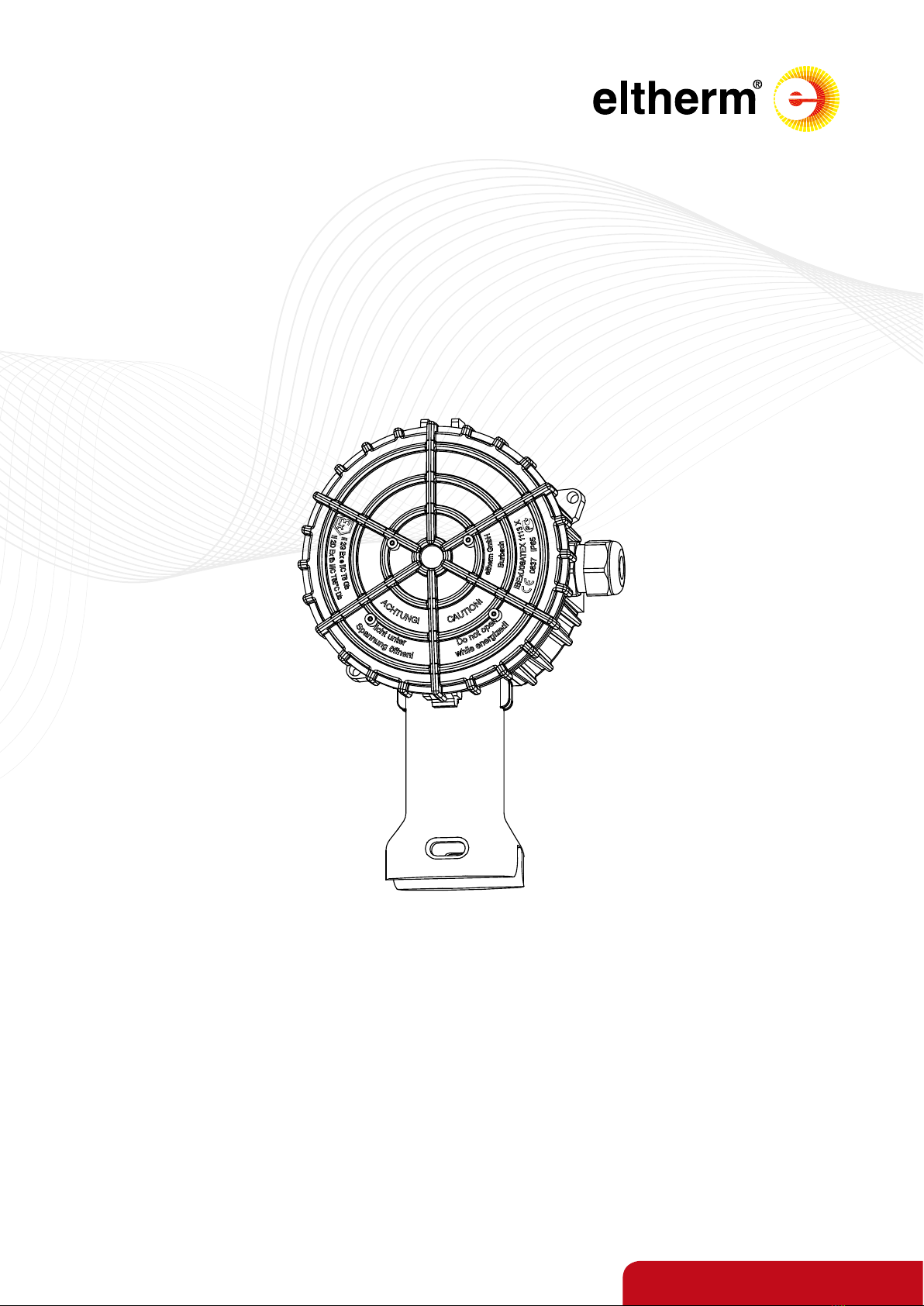
Ex – Junction box Ex-it-R
BU-139
Revision 0
ATTENTION
• The following steps should only be carried out by
persons trained in handling explosive equipment.
• Strict compliance with the relevant safety regulations in
potentially explosive atmospheres is a requirement for
the safety of persons, plants and equipment.
• The persons entrusted with the planning, installation
and maintenance bear a special responsibility and must
therefore be thoroughly familiar with the applicable
regulations.
• These instructions are intended for this group of people
and contain all the important information required for
the safe handling of the ELAK-Ex-R junction boxes.
• The instructions must be kept together with the system
documentation for later use and must be kept and be
available during the entire service life of the product.
SAFETY INSTRUCTIONS
RECEIPT OF THE GOODS
On receipt of the goods, check the junction boxes and the
accessories and compare the type information with the infor-
mation on the delivery note to ensure that the correct mate-
rial has been delivered.
STORAGE
Storage should be in a dry, clean place at an ambient
temperature from 0°C to 50°C.
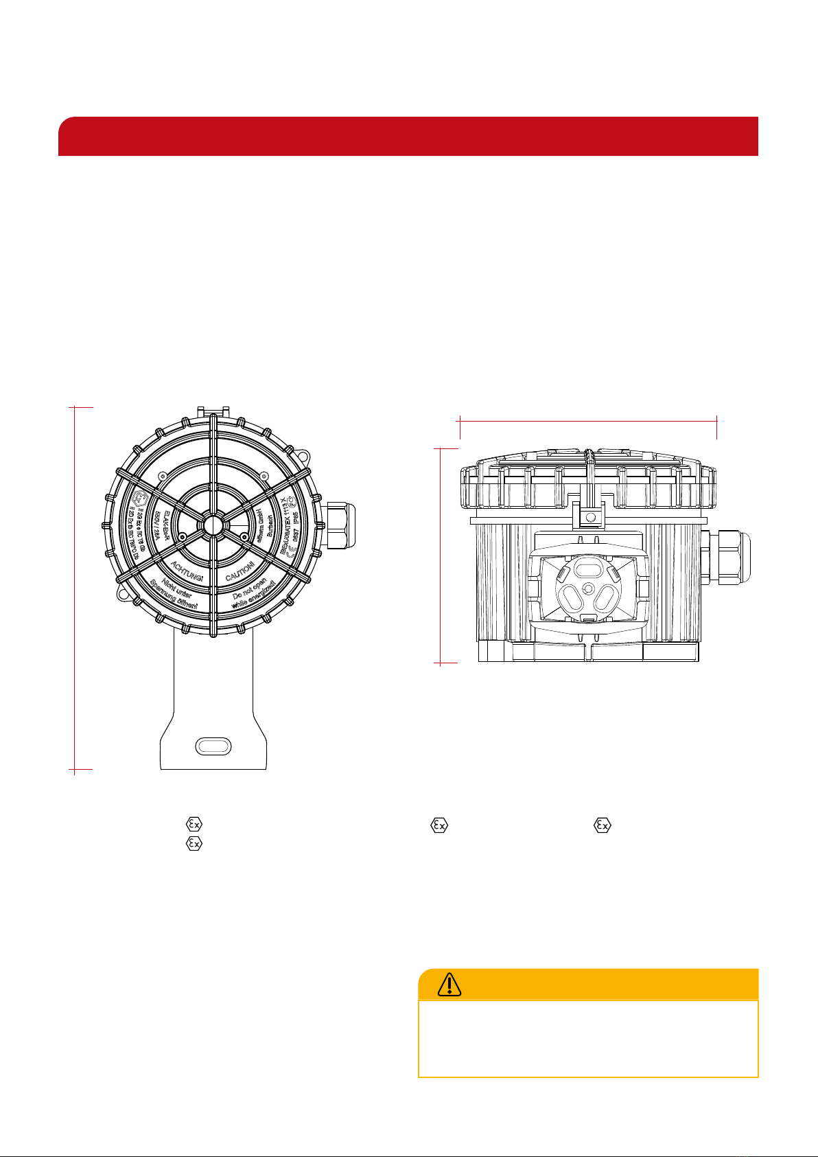
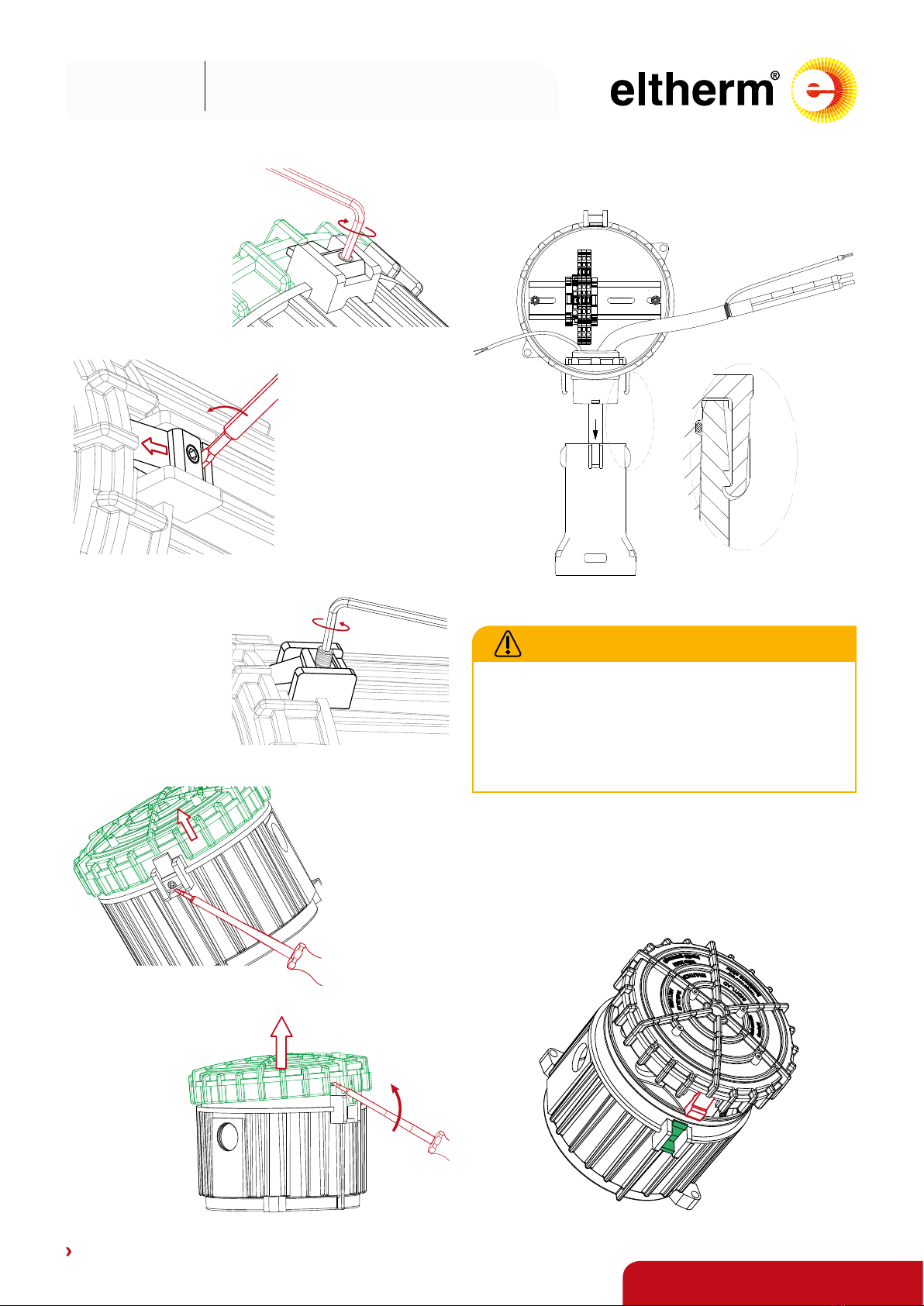
INSTALLATION
RECOMMENDED TOOLS
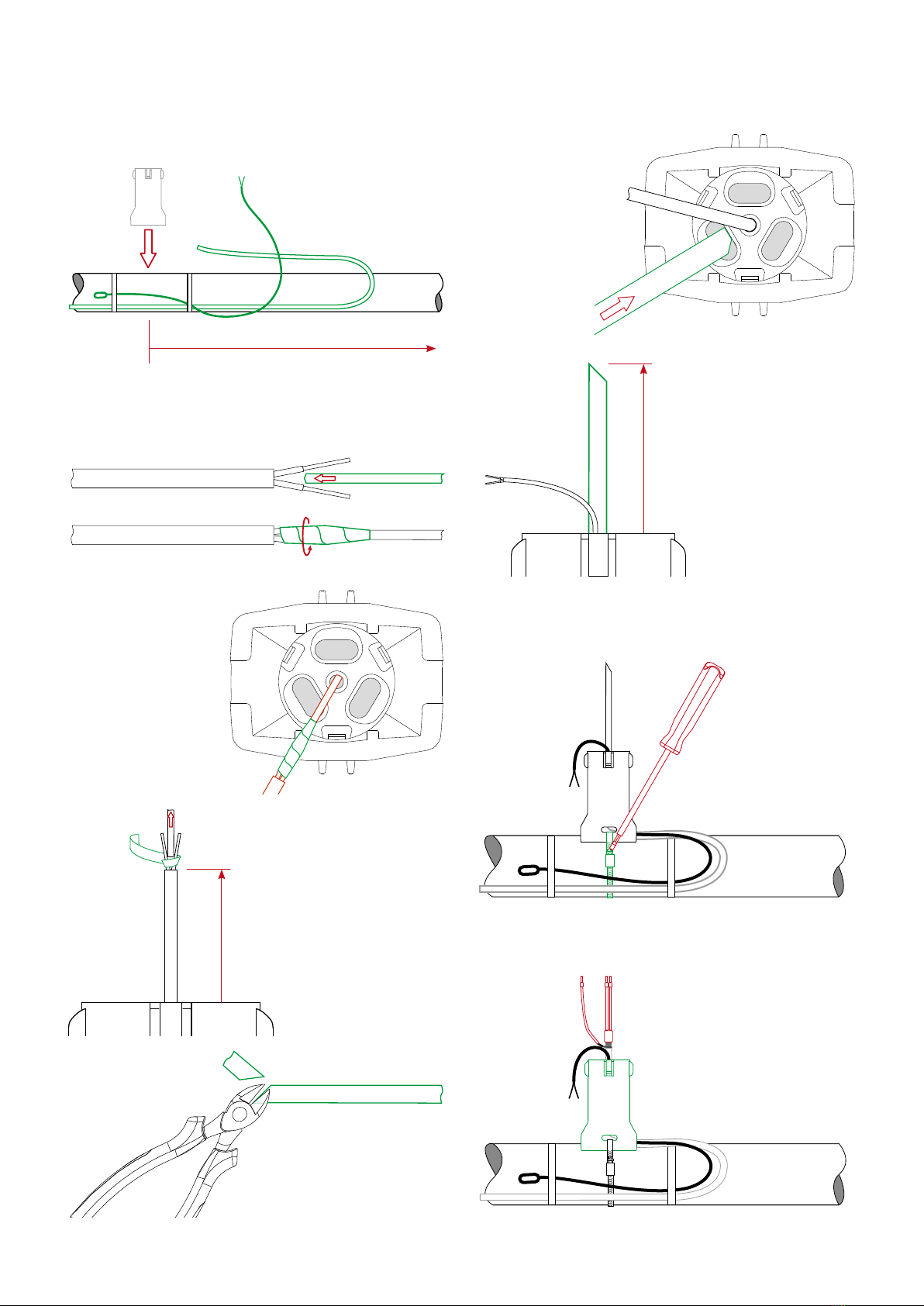
ASSEMBLY INSTRUCTIONS
ATTENTION
• When selecting the mounting location, take into ac-
count the degree of mechanical danger to the junction
box and the cable entries as well as the permissible am-
bient temperature.
• Ensure that the surface on which the junction box is
mounted is capable of bearing loads.
• Cables inserted into the junction box must be laid firmly
and secured against being pulled out of the cable entry
(e.g. by a cable clamp).
• Unused clamping points must be tightened.
• All cable entries, reducers and blind plugs may only be
used in conjunction with threaded connection seals, O-
rings or moulded sealing elements and must be separa-
tely tested and approved for type of protection „e“ or „t“
with EPL Gb or Db.
• Seals in the cable entries must not be exchanged or ne-
sted.
• Threaded boreholes can be reduced in size. However,
several reducers must not be reductions must not be
nested.
• Before inserting blind plugs, reducers or conduit entries
into free threaded boreholes, make sure that the threa-
ded borehole is clean and undamaged and that the re-
spective threads fit together.
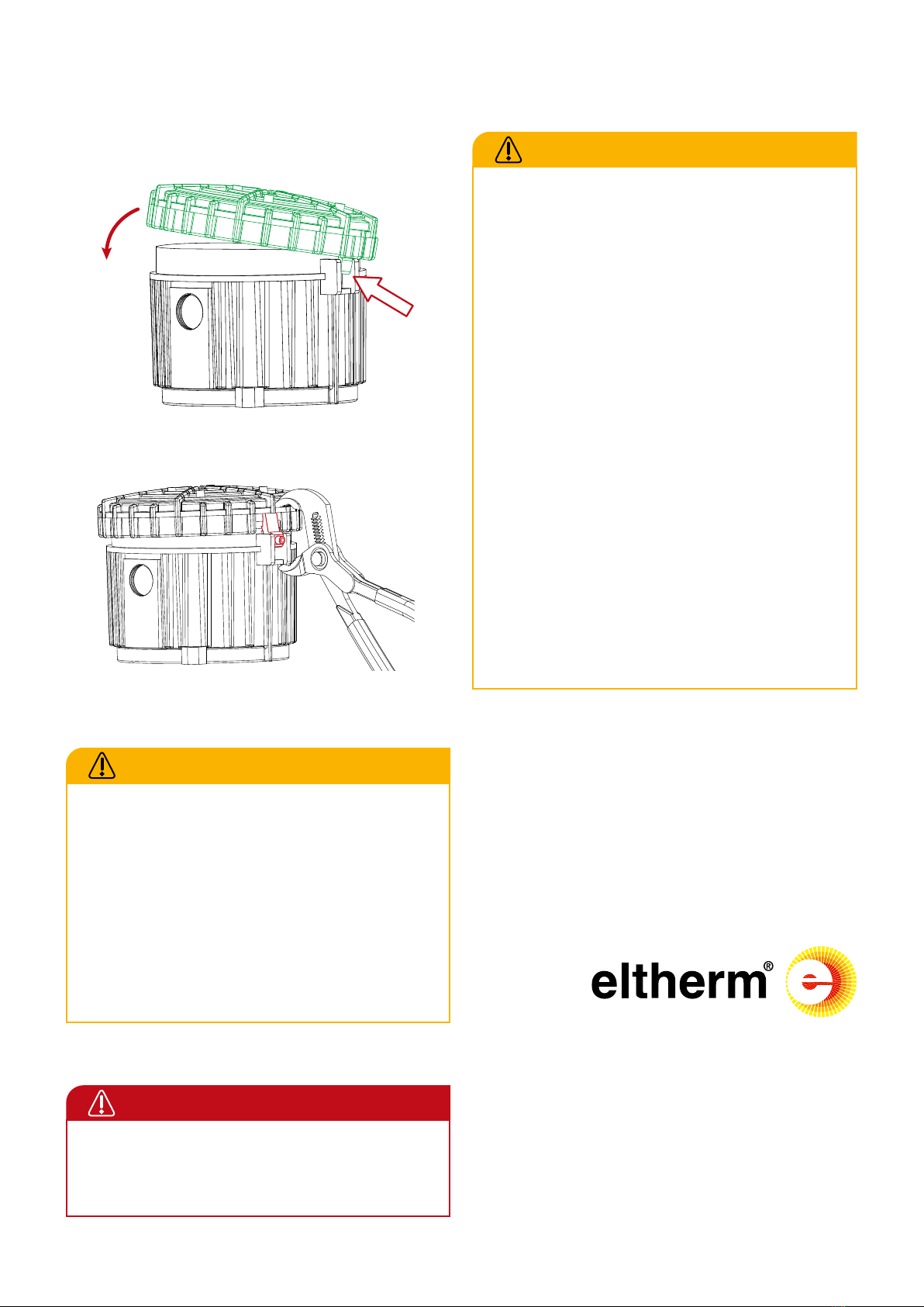
• After connection, all openings must be closed tightly
(cover, threaded boreholes, cable entries). Use suitable
open-end, ring or socket spanners to tighten the cable
entries. The torques (see before) must be observed.
• ATTENTION: Excessive tightening may impair the IP pro-
tection class!
• The lid of the junction box is designed to mount a iden-
tification plate provided by the customer. Use screws Ø
2.2 x 6 mm for fastening.
REQUIRED WRENCH SIZES
Size
Clamping
range
Wrench
size
Torques
Thread Screw
[mm] [mm] [Nm]
M20 5,5 - 13 24 3,75 3,5 - 2,5
M25 8 - 17 29 5 5 - 3