ELV Elektronik ETH Comfort User manual
Funk-Fensterkontakt
ETH comfort
Bedienungsanleitung
1. Bestimmungsgemäßer Einsatz
Der Fensterkontakt dient dazu, das Öffnen eines Fensters zu
detektieren. Ist der Fensterkontakt an einen Funk-Elektronik-
Thermostat angelernt (siehe 6), regelt dieser die Tempera-
tur im Raum während des Lüftens automatisch herunter.
Durch das automatische Temperaturabsenken bei geöff-
neten Fenstern lassen sich Heizkosten einsparen.
Betreiben Sie das Gerät nur in Innenräumen und vermei-
den Sie den Einfluss von Feuchtigkeit, Staub sowie Son-
nen- oder Wärmebestrahlung. Jeder andere Einsatz als
in dieser Bedienungsanleitung beschrieben ist nicht be-
stimmungsgemäß und führt zu Garantie- und Haftungs-
ausschluss. Dies gilt auch für Umbauten und Verände-
rungen. Die Geräte sind ausschließlich für den privaten
Gebrauch gedacht.
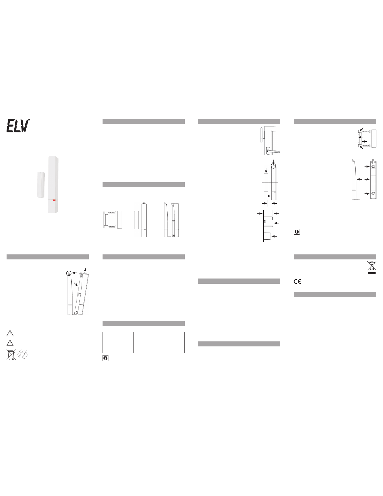
2. Übersicht
3. Vorbereitung der Montage
Der Fensterkontakt besteht grundlegend
aus zwei Elementen, einem Magneten (1)
und einer Elektronikeinheit (2). Ein Ele-
ment muss am Rahmen montiert sein,
das andere am Fenster. Dadurch kann
die Elektronikeinheit bei einer Fenster-
öffnung registrieren, dass sich der Ma-
gnet nun nicht mehr im direkten Umfeld
befindet und es wird ein „Fenster-auf“
Signal gesendet.
Montageort:
Wählen Sie zuerst das Fenster aus, das•
oft zum Lüften verwendet wird und an
dem der Fensterkontakt angebracht
werden soll.
Der Magnet (1) kann links oder rechts•
von der Elektronikeinheit (2) montiert
werden.
Die Elektronikeinheit (2) muss hoch-•
kant, mit der Entriegelungslasche (3)
oben, angebracht werden.
Abstände:
Der Abstand zwischen Magnet (1) und•
Elektronikeinheit (2) darf nicht größer
als 8mm (A) sein.
Der Magnet (1) und die Elektronikein-•
heit(2)müssen nebeneinanderauf einer
Ebene (B) angebracht werden.
Der Magnet (1) und die Elektronikein-•
heit (2) müssen mittig (C) nebeneinan-
der platziert sein.
4. Montage
Verwenden Sie zum Ausrichten die•
WandhalterungenderElektronikein-
heit (2) und des Magneten (1).
Markieren Sie gegebenenfalls die•
Bohrlöcher (a) von Magnet (1) und
Elektronikeinheit (2) an Rahmen und
Fenster mit einem Stift.
Die Befestigung von Magnet (1) Elektronikeinheit (2) kann
auf zwei Arten geschehen:
Klebestreifen-Variante
Hierbei entstehen keine Beschädi-•
gungen an Tür oder Fenster.
Verwenden Sie die mitgelieferten•
Klebestreifen.
K l e b e n S i e d i e S t r e i f e n a u f d i e R ü c k-•
seiten der Halterungen (1 und 2).
Drücken Sie dann die Halterungen•
an Rahmen und Fenster.
Schrauben-Variante
Bei hartem Untergrund sollten Sie die angezeichneten•
Löcher (a) mit einem 1,5 mm Bohrer vorbohren.
Verwenden Sie zur Befestigung der Elektronikeinheit (2)•
die mitgelieferten Senkkopfschrauben.
Nach Befestigung kann der tatsächliche Magnet (3) in•
die Magnethalterung (1) eingesetzt werden. Setzen Sie
abschließend die Abdeckkappe auf den Magneten.
Durch eine Schraubbefestigung wird der Rahmen
bzw. das Fenster beschädigt. Bei Mietwohnungen
könnte dies zu einer Schadensersatzforderung oder
zum Einbehalt der Mietkaution führen.
5. Batterien einlegen (wechseln)
Der Fensterkontakt wird mit 2 Batterien vom Typ LR03
(Micro/AAA) betrieben.
Drücken Sie die Entriegelungslasche•
(1) nach hinten.
Ziehen Sie das Oberteil nach schräg•
oben (2) von der Halterung ab.
Legen Sie 2 neue Micro-Batterien•
(LR03/AAA)polungsrichtig indas Bat-
teriefach (3) des Oberteils ein.
Setzen Sie das Oberteil wieder auf•
die Halterung und lassen Sie es ein-
rasten.
Bei zwei Fensteröffnungen für zwei
Stunden je Tag beträgt die Lebensdauer
neuer Alkali-Batterien ca. 5 Jahre.
Ein dreimaliges kurzes Blinken beim Öffnen oder Schließen
weist darauf hin, dass die Batterien auszutauschen sind.
Normale Batterien dürfen niemals aufgeladen wer-
den. Es besteht Explosionsgefahr.
Batterien nicht ins Feuer werfen!
Batterien nicht kurzschließen!
Verbrauchte Batterien gehören nicht in
den H ausmüll! Entsorg en Sie diese in Ihre r
örtlichen Batteriesammelstelle!
6. Anlernen von Funkkomponenten
Damit Funkkomponenten miteinander kommunizieren
können, müssen Sie aneinander angelernt sein. Der Fens-
terkontakt kann an Systemkomponenten wie einen Funk-
Elektronik-Thermostat angelernt werden.
Zuerst muss der Empfänger in den Anlernmodus ver-•
setzt werden. Lesen Sie dazu die Bedienungsanleitung
des entsprechenden Geräts.
Dann muss der Fensterkontakt zum Anlernen ein Signal•
aussenden. Öffnen oder schließen Sie dazu das Fenster.
I s t d e r F e n s te r k o n t a k t n o c h n i c h t m o nt i e r t, k a n n m a n M a -•
gnet und Elektronikeinheit einfach von einander trennen
oder aneinander legen. Bitte beachten Sie, dass dazu
die Batterien bereits eingelegt sein müssen.
Beim Senden leuchtet die LED des Fensterkontakts auf.•
Ein Fensterkontakt kann an beliebig viele Stellantriebe
angelernt werden.
7. LED Blinkfolgen und Sendeverhalten
Die Blinkfolge der LED hat unterschiedliche Bedeutungen:
Blinkfolge Bedeutung
1x blinken Kontakt/Fenster geschlossen
2x blinken Kontakt/Fenster geöffnet
3x blinken Batterie austauschen
Sollte der Fensterkontakt während des Sendens
(nach einer Fensteröffnung oder -schließung) fest-
stellen, dass die Batteriespannung zu niedrig ist, wird
nach dem Sendevorgang die Blinkfolge „Batterien
austauschen“ ausgegeben.
Nach einer Fensteröffnung oder -schließung sendet der
Fensterkontakt für 5 Sekunden. Während des Sendens
wird nicht auf weitere Änderungen reagiert. Sollte die
Position währenddessen geändert worden sein, wird der
neue Zustand direkt im Anschluss per Funk übertragen
und mittels LED-Blinkfolge dargestellt.
8. Hinweise zum Funkbetrieb
Die Funk-Übertragung wird auf einem nicht exklusiven
Übertragungsweg realisiert, weshalb Störungen nicht aus-
geschlossen werden können. Störeinflüsse können u.a.
durch Schaltvorgänge, Elektromotoren oder auch defek-
te Elektrogeräte hervorgerufen werden.
Die Reichweite in Gebäuden kann stark von der im Frei-
feld abweichen. Außer der Sendeleistung und den Emp-
fangseigenschaften der Empfänger spielen Umwelteinflüs-
se wie Luftfeuchtigkeit neben baulichen Gegebenheiten
eine wichtige Rolle.
Hiermit erklärt die ELV Elektronik AG, dass sich dieses
Gerät in Übereinstimmung mit den grundlegenden An-
forderungen und den anderen relevanten Vorschriften der
Richtlinie 1999/5/EG befindet. Die vollständige Konformi-
tätserklärung finden Sie unter www.elv.de.
9. Sicherheitshinweise
Die Geräte sind keine Spielzeuge, erlauben Sie Kindern
nicht damit zu spielen. Verpackungsmaterial nicht achtlos
liegen lassen, dies kann für Kinder zu einem gefährlichen
Spielzeug werden.
Öffnen Sie das Gerät nicht, es enthält keine durch den
Anwender zu wartenden Teile. Im Fehlerfall schicken Sie
das Gerät an den Service.
10. Entsorgungshinweis
Gerät nicht im Hausmüll entsorgen!
Elektronische Geräte sind entsprechend der Richt-
linie über Elektro- und Elektronik-Altgeräte über
die örtlichen Sammelstellen für Elektronik-Altge-
räte zu entsorgen!
Das CE-Zeichen ist ein Freiverkehrszeichen, das sich
ausschließlich an die Behörden wendet und keine
Zusicherung von Eigenschaften beinhaltet.
18. Technische Eigenschaften
Versorgungsspannung: 3 V
Batterien: 2x LR03 / Micro / AAA
Batterielebensdauer: ca. 5 Jahre
(2 Fensteröffnungen á 2h/Tag)
Empfängerfrequenz: 868,3 MHz
Reichweite im Freifeld: 30 m
Gehäuseabmessungen
Elektronikeinheit: 15 x 100 x 22 mm (B x H x T)
Magnet: 12 x 48 x 12 mm (B x H x T)
Technische Änderungen, die zur Verbesserung
dienen, sind vorbehalten.
Lesen Sie diese Anleitung sorgfältig, um das Gerät in Be-
trieb zu nehmen. Bewahren Sie die Anleitung zum späte-
ren Nachschlagen auf.
5
2
6
3
7
4
8
Elektronikeinheit
2
Fensterkontakt
1 2
Magnet
12
A
C
1
3
B
2
1
a
a
1
3
a
a
2
1
2
3
1. Ausgabe Deutsch 08/2009
Dokumentation © 2009 ELV Elektronik AG
Alle Rechte vorbehalten.
90401, V1.1, www.elv.com
ELV Elektronik AG · PF 1000 · D-26787 Leer

Radio shutter (window) contact
ETH comfort
Operating Manual
1. Intended use
This window contact is used to detect when a window is
opened. If the window contact is taught-in to radio electronic
thermostats (see 6), these devices will automatically reduce
the temperature in the room during ventilation. Using the au-
tomatic temperature reduction function whilst windows are
open enables heating costs to be lowered.
The device may only be operated indoors and must be pro-
tected from the effects of damp and dust, as well as solar
or other methods of heat radiation. Using the device for any
purpose other than what is described in this operating man-
ual does not fall within the scope of intended use and shall
invalidate any warranty or liability. This also applies to any
conversion or modification work. This device is intended for
domestic use only.
2. Overview
3. Preparing for installation
The window cont ac t consists of t wo fun-
damental ele m- ents: a magnet (1) and an
electronic unit (2). One of the elements
must be mounted on the frame, the other
on the window. This ensures that, when
the window is opened, the electronic unit
registers that the magnet is no longer in
the immediate vicinity and a “window
open” signal is transmitted.
Installation location:
First selectthewindowthat isfrequently•
used for ventilation and which the win-
dow contact is to be attached to.
The magnet (1) can be installed on the•
left or right of the electronic unit (2).
The electronic unit (2) must be at-•
tached upright with the release clip
(3) at the top.
Distances:
The magnet (1) and electronic unit•
(2) may not be any more than 8 mm
(A) apart.
The magnet (1) and electronic unit (2)•
must be attached next to one another
so that they are level (B).
The magnet (1) and electronic unit (2)•
must be positioned so that they are in
alignment next to one another (C).
4. Installation
Use the wall brackets for the elec-•
tronic unit (2) and magnet (1) to
align them.
If necessary, use a pen to mark the•
bore hole positions (a) for the mag-
net (1) and electronic unit (2) on the
frame and window.
•
The magnet (1) and electronic unit (2) can be fastened in
two ways:
Adhesive strip method
This does not damage the door or•
window in any way.
Use the adhesive strips supplied.•
Stick the strips on the rear sides of•
the brackets (1 and 2).
Then press the brackets onto the•
frame and window.
Screw method
If you are working with a hard surface, you should drill•
the holes marked (a) using a 1.5 mm drill.
Use the countersunk head screws supplied to fasten•
the electronic unit (2).
O n c e f a s t e n e d , t h e m a g ne t (3 ) c a n b e i n s e r te d i n t he m a g -•
net bracket (1). Then place the cap on the magnet.
Using screws will damage the frame and/or window.
For those living in rented accommodation, this could
lead to a landlord making a claim for compensation
or holding back a tenant’s deposit.
5. Inserting (replacing) batteries
The window contact is operated with 2 LR03 (Micro/AAA)
batteries.
Push the release clip (1) backwards.•
Pull the upper part of the device up•
and at an angle (2), and remove it
from the bracket.
Insert 2 new micro batteries (LR03/•
AAA) in the battery compartment (3)
of the upper part (making sure they
are the right way round).
Place the upper part back onto the•
bracket, allowing it to latch into
place.
The service life of new alkaline batter-
ies is approximately 5 years, based on
opening the window twice a day for two hours at a time.
If the LED flashes three times when the window is opened
or closed, this indicates that the batteries need to be
replaced.
Never recharge standard batteries. Doing so will
present a risk of explosion.
Do not throw the batteries into a fire.
Do not short-circuit batteries.
Used batteries should not be disposed
of with regular domestic waste. Instead,
they should be taken to your local battery
disposal point.
6. Teaching-in to radio components
To enable radio components to communicate with one
another,theyneed tobetaught-intooneanother.Thewindow
contact can be taught-in to system components such as a
radio electronic thermostat.
The first step is to switch the receiver) to teach-in mode.•
For information on how to do this, please refer to theope-
rating manual for the relevant device.
Following this, the window contact needs to transmit a•
signal for teaching-in purposes. To initiate this, open or
close the window.
If the window contact has not yet been installed, you•
can simply separate the magnet and electronic unit or
rest them against one another. However, please note
that the batteries must already have been inserted in
order to do this.
When a signal is transmitted, the window contact LED•
lights up.
A window contact can be taught-in to any number of ac-
tuators.
7. LED flashing sequences & transmission behaviour
The LED’s flashing sequences have different meanings:
Flashing sequence Meaning
1x flash Contact/window closed
2x flashes Contact/window open
3x flashes Replace batteries
If, whilst a signal is being transmitted (after the win-
dow has been opened or closed), the window contact
detects that the battery power is too low, the LED will
emit the “replace batteries” flashing sequence once the
signal has finished transmitting.
After a window has opened or closed, the window con-
tact transmits a signal for 5 seconds. Any further chan-
ges that are attempted while the signal is being transmit-
ted will not provoke a response. However, if the position
has been changed during this time, the new status will be
transmitted directly afterwards and indicated by an LED
flashing sequence.
8. Information on radio operation
Radio transmission is performed on a non-exclusive
transmission path, which means that there is a possibility
of interference occurring. Switching operations, electric
motors or faulty electric devices are some of the reasons
why interference may occur.
The range of transmission within buildings can deviate
greatly from open air distances. Besides the transmitting
power and the reception characteristics of the receiver,
environmental influences such as humidity in the vicinity
and structures also play an important role.
ELV Elektronik AG hereby declares that this device con-
forms with the essential requirements and other relevant
regulations of Directive 1999/5/EC. The full declaration of
conformity is provided at www.elv.de.
9. Safety instructions
These devices are not toys: do not allow children to play
with them. Do not leave packaging material lying around,
as this can be dangerous in the hands of a child.
Do not open the device: it does not contain any compon-
ents that need to be serviced by the user. In the event of
an error, please return the device to t he s ervice d epartmen t.
10. Disposal instructions
Do not dispose of the device with regular domestic
waste.
Electronic devices must be disposed of in ac-
cordance with the Waste Electrical and Electronic
Equipment Directive via local disposal points for
electronic waste.
The CE sign is a free trade sign addressed exclu-
sively to the authorities and does not warrant any
properties.
18. Technical caracteristics
Supply voltage: 3 V
Batteries: 2x LR03 / micro / AAA
Battery life: Approx. 5 years
(window opened twice a day for
2 hours at a time)
Transmission frequency: 868.3 MHz
Range of transmission
in open air: 30 m
Housing dimensions
Electronic unit: 15 x 100 x 22 mm (W x H x D)
Magnet: 12 x 48 x 12 mm (W x H x D)
We reserve the right to make any technical changes
that constitute an improvement to the device.
Please read this manual carefully in order to help you put
the device into operation. Keep the manual handy so you
can refer to it at a later date.
Electronic unit
2
Window contact
1 2
Magnet
12
A
C
1
3
B
2
1
a
a
1
3
a
a
2
1
2
3
Issue 1 English 08/2009
Documentation © 2009 ELV Elektronik AG
All rights reserved.
90401, V1.1, www.elv.com
5
2
6
3
7
4
8
ELV Elektronik AG · P.O.Box 1000 · D-26787 Leer
Table of contents
Languages:
Popular Indoor Furnishing manuals by other brands

Regency
Regency LWMS3015 Assembly instructions

Furniture of America
Furniture of America CM7751C Assembly instructions

Safavieh Furniture
Safavieh Furniture Estella CNS5731 manual

PLACES OF STYLE
PLACES OF STYLE Ovalfuss Assembly instruction

Trasman
Trasman 1138 Bo1 Assembly manual

Costway
Costway JV10856 manual


