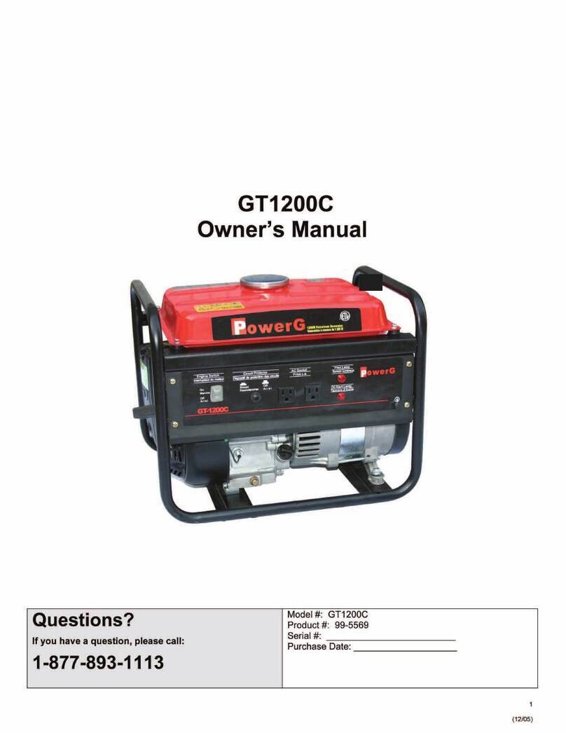
Elverk CCMAX 1200i Quick start guide

INVERTER GENERATOR
OPERATIONAL MANUAL

It contains how to use generator set in proper way, please read the operational
manual before use it. Safe & proper operation help the generator set in normal
running and prolongs its life span.
The issuing of technical data and drawings in this operational manual are all in
accordance with the newest products. For revision or other changes, the content of
this operational manual may be a little difference with actual situation. We reserve
the right to revise the operational manual in any time and without notice. Thanks for
understanding.
The ownership of this operational manual belong to our company, anyone
without permission in; written form is not allowed to issue copy Or you will be
prosecuted.
The operational manual is the permanent part of generator set. If the generator
be resold, the operational manual should be attached with together.

1

2
1.Safety Insruction.........................................................................................................
2.Component Identification............................................................................................
3.Operation and Control System....................................................................................
4.Start Generator..........................................................................................................
5.Stop The Generator...................................................................................................
6.Use Generator...........................................................................................................
7.Check Before Operation...........................................................................................
8.Start Engine And Connect The Load........................................................................
9.Maintenance..............................................................................................................
10.Storage And Transportation....................................................................................
11.Trouble Shooting....................................................................................................
12.Circuit Diagram......................................................................................................
13.Parameter...............................................................................................................
4
7
8
10
11
11
16
17
18
22
23
24
25

3
1.Safety Insruction

4

5

6
2.Component Identification
6
7
9
10
10.Choke valve
4
1
2
53
11
11.Oil switch
1.Fuel tank cap 2.Control panel
base
3.Control panel 4.Recoil starter
grip
5.Left shell 6.Handle
7.Muffler cover
plate
8.Appearance
cover plate
9.Engine oil
cover plate
1 ) Control Panel
1.Running light 2.Overload light 3.Engine oil lamp 4.Engine switch 5.Energy-
saving switch
7.Earthing terminal
8.AC socket 9.Reset switch
10.Parallel socket
4 5 3 2 19
10 8 11
6
7
6.DC breaker
11.DC plug

7
1) Generator Switch
The generator starts when the engine oil switch and flameout switch are on and the
choke is off.
2) Oil Indicator
When the oil in the crankcase is below the
safety line, the oil protection system will
automatically shut down the engine, and the oil
alarm indicator will be on; only when the oil is
filled to the oil level can the engine be started
again.
Tip: if the engine stops or fails to start, press
the switch to the "on" position, and then pull
the start handle. If the oil indicator flashes for a
few seconds, the oil capacity is insufficient. Fill
in oil and restart.
Overload light
Engine oil lamp
3) Overloaded Indicator
When the overload light is on, the generator detects that the output of the
connected electrical equipment has been overloaded, which causes the inverter to
overheat or the AC current to increase. At this time, the AC protector works and
stops the generator to protect the generator and the connected electrical equipment.
The AC indicator (green) is off and the overload indicator (red) is on, but the
engine will not stop.
When the overload indicator is on and the unit has no output, please take the
following measures:
1. Turn off the switch of the connected electrical equipment or pull out the
plug.
2. Press the self recovery reset button on the panel, and the operation indicator
on the panel turns green.
3. Reduce the load power of electrical equipment ≤ 1.1 times the rated output
power.
4. Press the idle switch to "off".
5. Turn on the power switch or plug in the power plug.
Tip: when using the electrical equipment with high starting current (such as
compressor, submersible pump, etc), the overload indicator light is just started It
may light up for a few seconds, but this is not the fault mentioned earlier.

8
4) AC Indicator
AC Indicator
5) DC Protector
6) ECO Switch
4350

9
7) Fuel Tank Cap
Turn counter clockwise to remove the tank cap.
8) Grounding Terminal
When the ground terminal is connected to the ground wire, to prevent electric
shock. When the electrical equipment is grounded, the generator must be grounded.
Grounding terminal
4.Start Generator
1) Turn the fuel tank cap knob to “ON”.
2) Turn the engine switch to “ON”.
3) a.Open the fuel
b.Choke closed

10
4) Stabilize the generator and pull the handle outward to make the generator run.
5) Turn the choke to “ON” to the left.
Notice: when pulling the hand starter, grasp the handling handle of the generator to
prevent the generator from overturning.
5.Stop The Generator
6.Use Generator
1)Generator Operating Environment
1) Stop all the electric equipment.
2) Turn the engine switch to “OFF”.
3) Turn the oil switch to “OFF”.
4) Put the cap ventilate button to “OFF” position when the generator totally cold.

11
OK ON
OK
2)Generator Wire Connection

12
Before starting the generator, it should be confirmed that the total power of
load electrical appliances should not exceed the rated power of the generator.
Overload working will shorten the generator life .
If there are several loads or equipments connected on the generator at the same
time, make sure firstly start the equipment that with highest starting current, then
middle one, finally to the lowest starting current one.
3)Generator Grounding
When using power electrical equipment above 800W, the energy saving switch
should be pressed to OFF.

13
Output Powe 1000W 800W 350W

14
If the carburetor which is suitable for high altitude be assembled on the
generator that is used in low altitude, the rare mixed gas will make the
generator power down, too hot or serious damage.
6)Used in High Altitude Area

15
Fuel the highest level
7.Check Before Operation
span
Synthetic 5W/30 oil is recommended
104F
86
68
50
32
14
4
-22
40C
30
20
10
0
-10
-20
-30
SAE 30
10W-30
*
Synthetic 5W-30
5W-30

16
l) Starting Engine
(4) Turn the choke handle to the right to the “close” position.
2) Connected To The Load
When using electrical equipment that needs large starting current, such as inductive and
capacitive loads, the fuel saving switch must be set in “off ” position;
8.Start Engine And Connect The Load

17
3) Overload Processing
or AC output current increases

18
0.33
Skin long -term and regular exposure to oil may cause skin cancer. Although this is not necessarily
necessary, it is recommended to use soap and water to wash the skin immediately and thoroughly.
From an environmental point of view, please deal with the waste oil produced after use. We strongly
recommend that you put the waste oil into a sealed container and send it to a local service station or a
waste oil recycling center. Remember: do not thrown into the garbage or dumped on the ground, ditch.
1)Oil Change
Table of contents
Popular Portable Generator manuals by other brands
EWM
EWM Tetrix 451 AC/DC Smart 2.0 FW operating instructions
Westinghouse
Westinghouse iGen2200c user manual
Bowens
Bowens QUAD BWL-0350/1 user guide
Generac Power Systems
Generac Power Systems XP Series owner's manual
Mosa
Mosa FPT GE 335 FSX Use and maintenance manual

Parker
Parker N2-120 Installation, operation & maintenance manual

