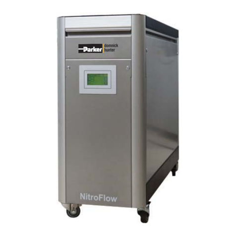
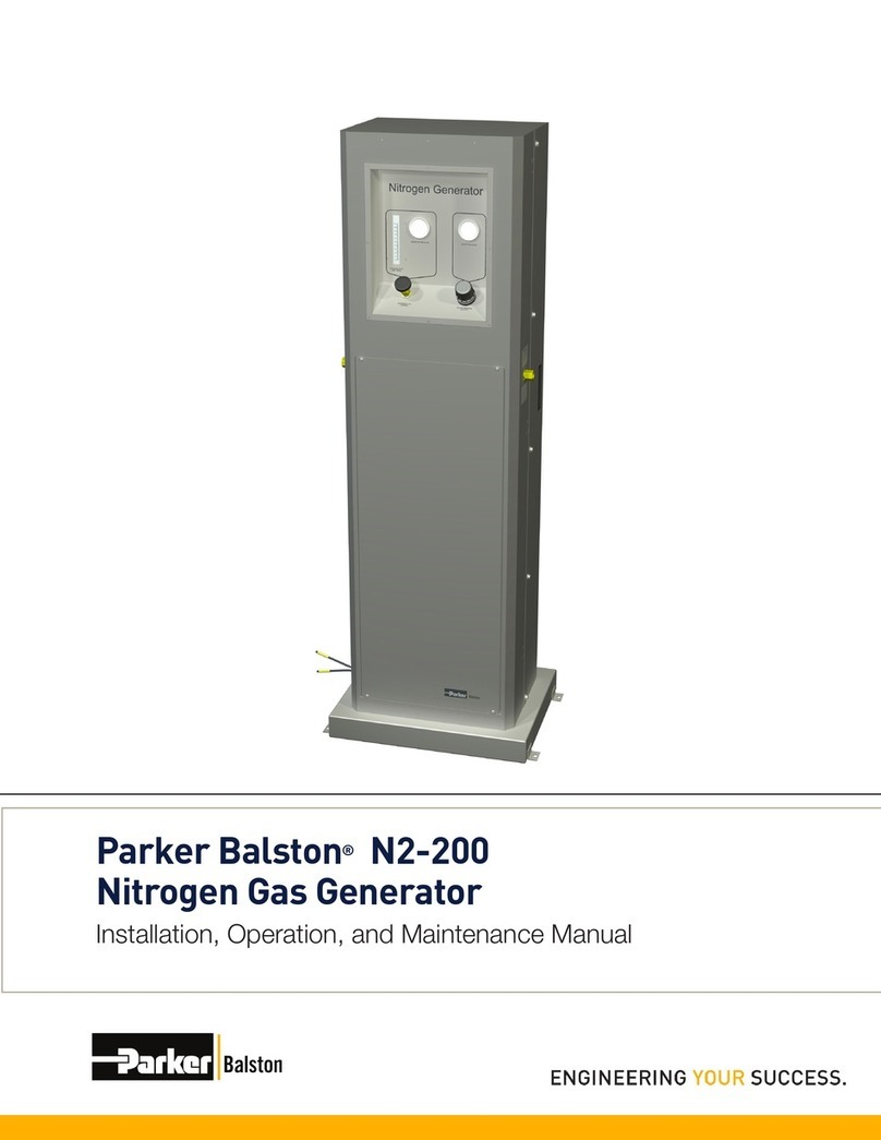
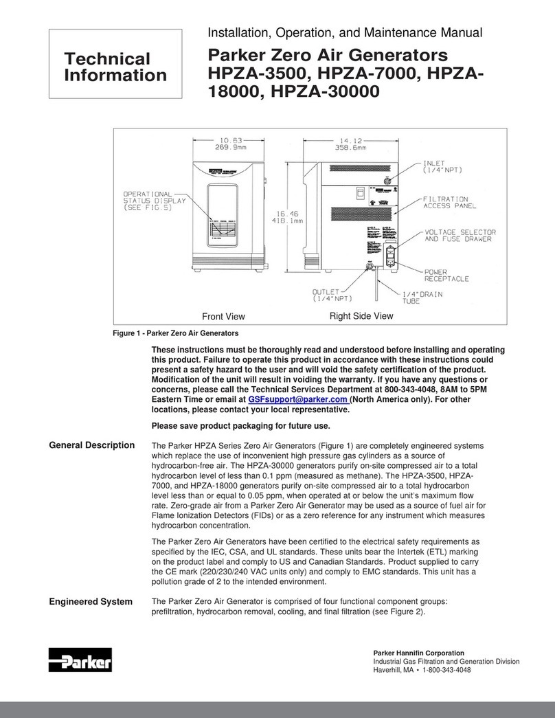
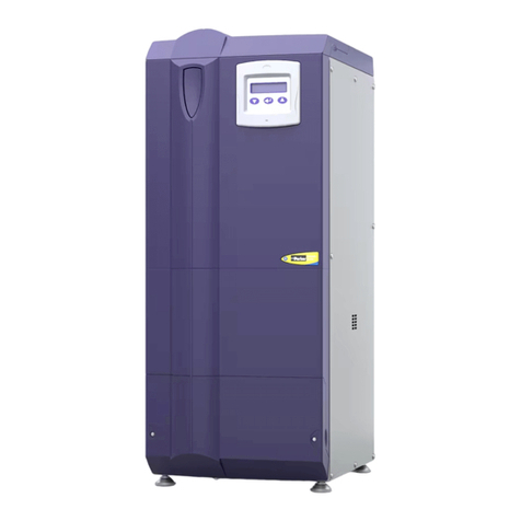
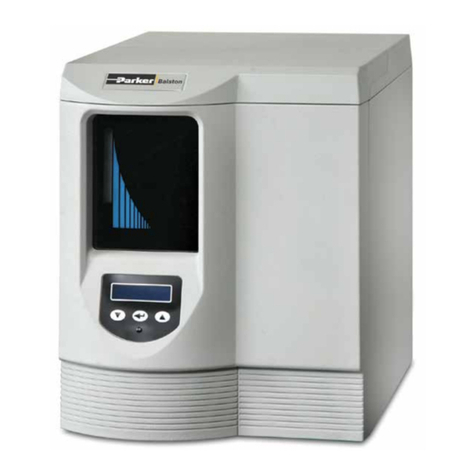
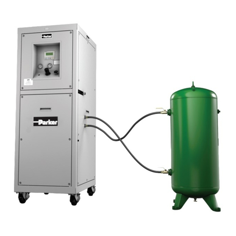
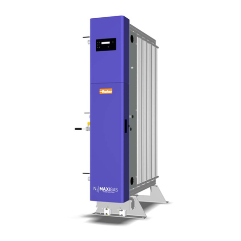
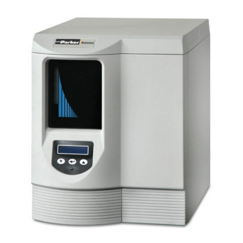
Parker N2-120 Instruction manual

Nitrogen Generator Installation,
Operation, & Maintenance Manual
Models: N2-120, N2-160, N2-240

NITROGEN GENERATORSINSTALLATION, OPERATION, AND MAINTENANCE MANUAL
1

2
NITROGEN GENERATORSINSTALLATION, OPERATION, AND MAINTENANCE MANUAL
TABLE OF CONTENTS
Page
1. WARRANTY.............................................................................................................3
2. SAFETY PRECAUTIONS...........................................................................................4
3. GENERAL DESCRIPTION.........................................................................................5
4. ENGINEERED SYSTEM............................................................................................5
4.1 Prefiltration .......................................................................................................6
4.2. Air Separation ..................................................................................................6
4.3 Final Filtration ....................................................................................................6
4.4 Controls ............................................................................................................6
5. OXYGEN MONITORING ...........................................................................................7
6. INSTALLATION .......................................................................................................7
6.1 Moving..............................................................................................................7
6.2 General.............................................................................................................8
6.3 Location............................................................................................................9
6.4 Utilities..............................................................................................................9
6.5 Installation with a Receiver Tank........................................................................ 10
7. OPERATION ......................................................................................................... 11
7.1 Startup............................................................................................................ 11
7.2 System Adjustment for Desired Outlet Purity...................................................... 11
8. NITROGEN FLOW AT GIVEN OPERATING PRESSURE AND PURITY .......................... 12
9. OPERATION ADJUSTMENT PROCEDURES.......................................................... 14
9.1 Atmospheric Pressure Applications (<10 psig / 0.7 barg).................................... 14
9.2 Elevated Pressure Applications (>10 psig) ......................................................... 15
9.3 Receiving Tank Applications ............................................................................. 16
9.4 Temperature Equilibrium .................................................................................. 16
9.5 Evaluation ....................................................................................................... 17
9.6 System Upsets ................................................................................................ 17
9.7 Shutting Down ................................................................................................. 17
10. MAINTENANCE................................................................................................... 17
10.1 Cleaning........................................................................................................ 18
10.2 Filter Cartridge Replacement .......................................................................... 18
10.3 Activated Carbon Filter Replacement............................................................... 19
10.4 Ordering Information...................................................................................... 19
11. NITROGEN GENERATION SYSTEM SPECIFICATIONS ........................................... 20
11.1 Approximate Inlet Air Consumption at 68°F by Purity and Pressure..................... 20
11.2 Optional Accessories...................................................................................... 21
11.3 Cautions........................................................................................................ 21
12. TROUBLESHOOTING .......................................................................................... 22
3
NITROGEN GENERATORSINSTALLATION, OPERATION, AND MAINTENANCE MANUAL
1. WARRANTY
SERIAL NUMBER
Each major component in this unit has a serial number. A serial number for the entire unit is
attached to the left side panel, near the inlet port. For your own records, and in case service is
required, please record the following:
Date In Service:
Serial No.
WARRANTY (NORTH AMERICA ONLY)
(FOR INFORMATION CONTACT YOUR LOCAL REPRESENTATIVE)
Parker Hannifin guarantees to the original purchaser of this product, that if the product fails
or is defective within 12 months from the date of purchase, when this product is operated and
maintained according to the instructions provided with the product, then Parker guarantees, at
Parker’s option, to replace the product, repair the product, or refund the original price for the prod-
uct. This warranty applies only to defects in material or workmanship and does not cover: ring and
valve wear on compressors, routine maintenance recommended by the instructions provided with
this product, or filter cartridges. Any modification of the product without written approval from
Parker will result in voiding this warranty. Complete details of the warranty are available on request.
This warranty applies to units purchased and operated in North America.
MEMBER OF
R
E
C
Y
C
L
A
B
L
E
•
R
E
C
Y
C
L
A
B
L
E
•
R
E
C
Y
C
L
A
B
L
E
•

4
NITROGEN GENERATORSINSTALLATION, OPERATION, AND MAINTENANCE MANUAL
2. SAFETY PRECAUTIONS
These instructions must be thoroughly read and understood before installing and operating
this product. Failure to operate this product in accordance with the instructions set forth in this
manual and by other safety governing bodies will void the safety certification of this product. Any
modification of the product will void the warranty. If you have any questions or concerns, please
call the Technical Services Department at 1-800-343-4048, 8 AM to 5 PM Eastern Time or email
at GSFsupport@parker.com. (North America only). For other locations, please contact your
local representative.
EXPLANATION OF WARNING SYMBOLS
Caution. Refer to accompanying documents for explanation.

5
NITROGEN GENERATORSINSTALLATION, OPERATION, AND MAINTENANCE MANUAL
3. GENERAL DESCRIPTION
The Parker Nitrogen Generators are completely engineered systems which will convert a compressed
air supply into a 95% to 99.5% purity compressed nitrogen gas. Nitrogen purities as high as 99.9%
can be achieved with significant reduction in output flow. The system is based on state-of-the-art
membrane separation technology. Hollow fiber membranes are used to separate air into a concentrated
nitrogen output stream and an oxygen enriched permeate stream. The model number of the generator
represents the approximate nitrogen flow in standard liters per minute that can be achieved at a
purity of 97% with a 100 psig (6.9 barg) outlet pressure. To achieve this outlet pressure, the inlet
pressure needs to be approximately 110-115 psig (7.6-7.9 barg).
4. ENGINEERED SYSTEM
The Parker N2-120, N2-160, and N2-240 Nitrogen Generators have been certified to IEC 1010
Standards (CSA 22.2 No. 61010-1-12). The generators bear the CSA safety marking on the
product label.
The Parker Nitrogen Generators include all the components required to generate high purity
nitrogen gas from compressed air. The user need only connect a supply of compressed air to the
inlet of the nitrogen generator and connect the outlet of the generator to the process requiring high
purity nitrogen.
The flow schematic (Figure 2) shows all of the major components of the system. The system can
be broken down into four primary functional groups. These are: prefiltration, air separation, flow
controls, and final filtration.
Figure 1
Nitrogen Generators

6
NITROGEN GENERATORSINSTALLATION, OPERATION, AND MAINTENANCE MANUAL
4.1 Prefiltration
Two Balston®high efficiency coalescing filters, an activated carbon filter, and a particulate filter are
incorporated into the Parker Nitrogen Generators to protect the membrane module from contamina-
tion. The coalescing filters are located behind the filtration access panel. They remove liquids and
particulate matter from the incoming air supply to 0.01 micron. These filters are equipped with float
drains which automatically open to empty any liquids which accumulate inside the filter housing. The
drains are connected to 1/4" O.D. plastic tubing which discharges to atmosphere on the left side of
the generator (see Figure 1).
The activated carbon filter removes hydrocarbons from the compressed air before it enters the
separation module. A Balston high efficiency particulate filter is installed between the activated
carbon filter and the separation module to protect the membrane from carbon dust.
4.2 Air Separation
Air separation takes place in the membrane modules. The modules consist of bundles of hollow
fiber membranes. As the air passes through these hollow fibers, oxygen and water molecules pass
through the membrane wall at a higher rate than nitrogen molecules. This differential permeation
results in a high purity, dry nitrogen gas stream exiting the membrane module. The oxygen enriched
permeate stream is exhausted through ports on the membrane module at a very low pressure.
4.3 Final Filtration
The final filter on the generators is a Balston Grade GS membrane filter. The final membrane
filter removes particulate contamination to 0.01 micron (absolute), and assures the user a clean,
commercially sterile supply of high purity nitrogen.
4.4 Controls
The flow controls integral to the Parker Nitrogen Generators comprise: an operating pressure
gauge, a flowmeter, a flow control valve, an outlet pressure gauge, and an outlet pressure regulator
(see Figures 1 and 2). Proper use of these controls will assure the user of a 95% to 99.5% purity
nitrogen outlet stream. The pressure gauges, mounted on the front panel, measure operating pres-
sure and outlet pressure. The outlet pressure regulator allows the user to set the pressure of the outlet
nitrogen process stream. The flow control valve sets the flow rate of nitrogen exiting the membrane
module. The scale on the flowmeter is dimensionless because the operating pressure can range from
60 psig (4.1 barg) to 145 psig (10 barg). The flowmeter adjustment label on the control panel is used
to convert the dimensionless flowmeter reading into standard liters per minute of outlet nitrogen
based on operating air pressure.

7
NITROGEN GENERATORSINSTALLATION, OPERATION, AND MAINTENANCE MANUAL
5. OXYGEN MONITORING
Note: In hazardous applications where the oxygen content is critical (i.e., blanketing explosive
chemicals or packaging food for extended shelf life), an oxygen monitor and/ or trace oxygen
analyzer should be used in conjunction with safety interlocks and/or alarm systems to assure
proper nitrogen purity levels at all times.
If an oxygen analyzer is needed, Parker Model 72-730NA, which has built-in alarms for connection
to external relays, may be used. This oxygen analyzer has all the controls necessary to assure safe
and accurate monitoring of the oxygen concentration in a process stream. It can be easily installed
on top of the nitrogen generator and connected to the outlet nitrogen line using appropriate fittings.
6. INSTALLATION
All installation, operation, and maintenance procedures should be performed by suitable
personnel using reasonable care.
6.1 Moving
The Parker N2-120, N2-160, and N2-240 Nitrogen Generators are shipped on a wooden skid.
Use a lifting device designed for moving skidded products to move the generator to its installation
location. Gently move the generator from the skid to its final installation position. Secure to floor
if desired. If a future move is required, the generator should be returned to a skid and moved as
detailed above. For moves over short distances, the generator may be slid on its supporting base
or moved using a two-wheeled moving device.
Figure 2
Flow Schematic

8
NITROGEN GENERATORSINSTALLATION, OPERATION, AND MAINTENANCE MANUAL
Figure 3
Top View of Base Holes
6.2 General
The Nitrogen Generators are free-standing units. Do not suspend the nitrogen generator from
a wall or ceiling. Its considerable weight and size could pose a falling hazard. Holes have been
pre-drilled in the base of the generator (see Figure 3) to secure it to the floor, if desired.
The inlet and outlet ports on the nitrogen generators are 1/2" female NPT. A 1/2" male connector
which will withstand 145 psig (10 barg) should be used to connect to the nitrogen generator. Parker
offers an installation kit (P/N IK75880) which combines all the basic fittings and refrigeration grade
copper tubing required to bring the system online. This kit can be used to connect the generator
to up to 2 instruments and to the compressed air supply. See Figure 4 for the recommended
installation schematic.
Shutoff Valve - A shutoff valve should be installed directly upstream from the nitrogen generator
to facilitate routine maintenance and troubleshooting procedures. The valve should always be
opened slowly. Opening a valve quickly will pressurize the membrane too rapidly and may cause
membrane rupture. Membrane failures resulting from improper valve installation will not be covered
under warranty.
Pressure Regulator - A pressure regulator should be installed directly upstream from the nitrogen
generator to set and maintain the inlet air pressure. Maintaining a constant inlet air pressure is
critical to the performance of the system.
Flow Controller - If the application requires nitrogen at pressures higher than 10 psig (0.7 barg),
install a flow controller downstream from the nitrogen generator, close to the point of use
(see Adjustment Procedure section, page 14).

9
NITROGEN GENERATORSINSTALLATION, OPERATION, AND MAINTENANCE MANUAL
Figure 4
Recommended Installation
6.3 Location
The generator should be located indoors, protected from severe weather conditions, and free
from excessive ambient dust or dirt. Do not install the generator outdoors. Ensure that the
ambient temperature of the air surrounding the generator is within the range of that specified for
the generator (see specifications page 20). Allow a minimum of 6" (15 cm) clearance on all sides
of the generator.
The environment surrounding the nitrogen generator should also be adequately ventilated. The
generator creates a 30% to 40% oxygen permeate stream which may pose a flammability risk
in an oxygen sensitive environment.
6.4 Utilities
Compressed Air - The Parker Nitrogen Generators require a source of compressed air at room
temperature and relatively free of water, compressor oil, hydrocarbons, and particulate matter. An oil
content <0.01 mg/m3is recommended. The dewpoint of the incoming air is recommended to be less
than or equal to 40°F (5°C) at 145 psig. The compressed air should be as close to instrument quality
as possible and regulated to a pressure between 60 psig and 145 psig (4.1 barg and 10 barg),
depending on downstream flow and purity desired.
DO NOT OPERATE THE NITROGEN GENERATOR WITHOUT THE FRONT SHEET METAL FILTER
ACCESS PANEL SECURED IN PLACE.
Note: The piping and fittings on the inlet air delivery system should be at least the same size as the
inlet port on the generator. This will help ensure an adequate supply of air to the generator.
Drain Lines - The 1/4" plastic drain lines from the first two stages of prefiltration (see Figure 1)
should be piped away to an appropriate disposal container. The liquid in this drainage will consist
primarily of water and compressor oil and should be disposed of properly.

10
NITROGEN GENERATORSINSTALLATION, OPERATION, AND MAINTENANCE MANUAL
6.5 Installation with a Receiver Tank
In many applications, the process flow requirement for nitrogen fluctuates with time. A receiver
tank can be installed between the nitrogen generator and the process to accommodate fluctuations
in nitrogen demand while maintaining nitrogen purity.
If a receiver tank is to be used, a back pressure regulator and a check valve should be installed
between the Parker Nitrogen Generator and the receiver tank (see Figure 5). The Balston 72-460-
V883 Back Pressure Controller contains both components and may be ordered as an accessory for
the Nitrogen Generator. The adjustable back pressure regulator, when set to the appropriate pres-
sure, will maintain a constant pressure drop across the flow control valve. By controlling the pressure
drop across the flow control valve, the nitrogen flow and purity will be kept constant. The check valve,
when installed properly, will prevent any backflow of nitrogen from the receiver, providing a more
effective means of storing the nitrogen.
Figure 5
Recommended Installation with a Receiving Tank

11
NITROGEN GENERATORSINSTALLATION, OPERATION, AND MAINTENANCE MANUAL
7. OPERATION
7.1 Startup
The inlet and outlet connections to the Parker Nitrogen Generator must be checked for leaks prior
to system start-up. After the system is properly installed and checked for leaks, the inlet gate valve
can be slowly opened to introduce compressed air to the system.
During start-up and adjustment of the system, the nitrogen produced by the system will vary in
purity. If the application for the nitrogen is critically dependent on purity, the nitrogen produced
during start-up or adjustment should be vented.
If the outlet nitrogen flow is closed, the system will still consume compressed air. The inlet air is
simply vented to atmosphere through the permeate ports of the membrane module. To eliminate
compressed air consumption if nitrogen is not required for the process, shut off the compressed
air supply to the generator.
7.2 System Adjustment for Desired Outlet Purity
The inlet air pressure must be constant for the system to supply nitrogen of consistent purity to
the application. The inlet pressure to the Parker Nitrogen Generator should be maximized (within
process and generator parameters) to optimize the operation of the membrane module. The inlet
air consumption for different operating pressures is shown in the table on page 20. Nitrogen purities
and flow rates for different operating pressures are shown on page 12.
Flowmeter settings for a given operating pressure are shown on the Nitrogen Purity label attached
to the front of the unit and displayed on the next page. There may be a 5 psig to 15 psig pressure
differential between the pressure of the compressed air supply at the inlet and the operating pressure
of the membrane module. The pressure differential observed is dependent on the outlet nitrogen flow
rate as well as the operating pressure. This pressure loss must be taken into account when
determining the inlet pressure which will deliver the desired purity and flow of nitrogen from
the generator.
To adjust the pressure regulator on the front panel of the generator, pull the knob out, adjust
the pressure and push the knob back in to lock the setting.

12
NITROGEN GENERATORSINSTALLATION, OPERATION, AND MAINTENANCE MANUAL
8. NITROGEN FLOW AT GIVEN OPERATING PRESSURE AND PURITY
Notes on flow rate and purity:
1. On the generator, the flow meter units are dimensionless. For N2-160 & N2-240, read
flowmeter at the middle of the ball. For N2-120, read flow meter at the top of the ball. The
actual flow at various operating pressures is converted into standard liters per minute (SLPM)
in the purity label on the unit.
2. Minimum purity is shown in percent nitrogen. All nitrogen purities are ±0.5%. If a more
accurate reading is required, an oxygen analyzer is recommended.
3. All data shown in the table is based on an operating temperature of 25°C (77^F).
4. All flows should be verified with an auxiliary flowmeter at the point of use.
MIN
Purity
% N2
60 PSIG 70 PSIG 80 PSIG 90 PSIG 100 PSIG 125 PSIG 145 PSIG
Meter SLPM Meter SLPM Meter SLPM Meter SLPM Meter SLPM Meter SLPM Meter SLPM
99.50 0.7 32 0.9 43 1.1 54 1.3 66 1.5 78 1.9 110 2 .1 133
99.00 1.0 43 1.2 55 1.5 71 1.7 89 2.0 106 2.5 149 2.9 183
98.00 1.4 60 1.7 79 2.1 101 2.4 124 2.7 147 3.6 212 4.1 258
9 7.0 0 1.8 76 2.2 102 2.7 130 3.1 159 3.5 187 4.5 264 5 .1 325
96.00 2.1 90 2.7 125 3.3 159 3.8 194 4.2 228 5.4 320 6.3 400
95.00 2.5 107 3 .1 141 3.7 180 4.3 222 5.0 268 6.3 375 7.4 467
Model N2-240
MIN
Purity
% N2
4 BARG 5 BARG 6 BARG 7 BARG 8 BARG 9 BARG 10 BARG
Meter SLPM Meter SLPM Meter SLPM Meter SLPM Meter SLPM Meter SLPM Meter SLPM
99.50 0.7 30 1.0 46 1.3 63 1.6 80 1.8 100 2.0 117 2.1 133
99.00 0.9 40 1.3 58 1.7 83 2.1 108 2.3 133 2.7 158 2.9 183
98.00 1.3 57 1.8 83 2.4 117 2.9 150 3.3 192 3.8 225 4.1 258
9 7.0 0 1.6 71 2.3 108 3.1 150 3.7 192 4.1 233 4.8 283 5.1 325
96.00 1.9 83 2.9 133 3.8 183 4.3 233 4.9 283 5.8 342 6.3 400
95.00 2.3 100 3.2 150 4.3 208 5.2 275 5.7 333 6.7 400 7.4 467
Model N2-240

13
NITROGEN GENERATORSINSTALLATION, OPERATION, AND MAINTENANCE MANUAL
MIN
Purity
% N2
60 PSIG 70 PSIG 80 PSIG 90 PSIG 100 PSIG 125 PSIG 145 PSIG
Meter SLPM Meter SLPM Meter SLPM Meter SLPM Meter SLPM Meter SLPM Meter SLPM
99.50 0.9 24 1.2 32 1.4 41 1.6 50 1.9 59 2.4 83 2.7 100
99.00 1.3 32 1.5 41 1.9 53 2.2 66 2.5 79 3.2 112 3.7 138
98.00 1.8 45 2.2 59 2.6 75 3.1 93 3.5 110 4.6 159 5.2 194
9 7.0 0 2.2 57 2.8 76 3.4 97 3.9 119 4.4 141 5.7 198 6.5 244
96.00 2.7 68 3.4 94 4.2 119 4.8 145 5.4 171 6.9 240 8.0 300
95.00 3.1 80 3.9 106 4.7 135 5.5 167 6.4 201 8.1 281 9.4 350
Model N2-160
MIN
Purity
% N2
4 BARG 5 BARG 6 BARG 7 BARG 8 BARG 9 BARG 10 BARG
Meter SLPM Meter SLPM Meter SLPM Meter SLPM Meter SLPM Meter SLPM Meter SLPM
99.50 0.9 23 1.3 34 1.6 47 2.0 60 2.2 75 2.5 88 2.7 100
99.00 1.2 30 1.6 44 2.2 63 2.7 81 2.9 100 3.4 119 3.7 138
98.00 1.7 43 2.3 63 3.0 88 3.7 113 4.2 144 4.8 169 5.2 194
9 7.0 0 2 .1 53 3.0 81 3.9 113 4.8 144 5.1 175 6.1 213 6.5 244
96.00 2.5 63 3.7 100 4.8 138 5.8 175 6.4 213 7.3 256 8.0 300
95.00 2.9 75 4.1 113 5.4 156 6.8 206 7.6 250 8.6 300 9.4 350
Model N2-160
MIN
Purity
% N2
60 PSIG 70 PSIG 80 PSIG 90 PSIG 100 PSIG 125 PSIG 145 PSIG
Meter SLPM Meter SLPM Meter SLPM Meter SLPM Meter SLPM Meter SLPM Meter SLPM
99.50 -16 -22 -27 -33 2.0 39 2.2 55 2.5 67
99.00 -21 -28 2.0 36 2.0 44 2.3 53 2.9 74 3.4 92
98.00 -30 2.0 39 2.4 50 2.8 62 3.2 73 4.2 106 4.7 129
9 7.0 0 2.0 38 2.6 51 3 .1 65 3.6 79 4.1 94 5.2 132 6.0 163
96.00 2.4 45 3.1 62 3.8 80 4.4 97 4.9 114 6.3 160 7.4 200
95.00 2.9 53 3.6 71 4.3 90 5.0 111 5.8 134 7.4 187 8.6 233
Model N2-120

14
NITROGEN GENERATORSINSTALLATION, OPERATION, AND MAINTENANCE MANUAL
MIN
Purity
% N2
4 BARG 5 BARG 6 BARG 7 BARG 8 BARG 9 BARG 10 BARG
Meter SLPM Meter SLPM Meter SLPM Meter SLPM Meter SLPM Meter SLPM Meter SLPM
99.50 -15 -23 -31 2.0 40 2.2 50 2.3 58 2.5 67
99.00 -20 -29 2.0 42 2.3 54 2.9 67 3.1 79 3.4 92
98.00 -28 2.1 42 2.8 58 3.3 75 4.2 96 4.4 113 4.7 129
9 7.0 0 -35 2.7 54 3.6 75 4.2 96 5.1 117 5.6 142 6.0 163
96.00 2.3 42 3.4 67 4.4 92 5.0 117 6.1 142 6.7 171 7.4 200
95.00 2.8 50 3.8 75 5.0 104 5.9 138 7.2 167 7. 2 200 8.6 233
Model N2-120
9. OPERATION ADJUSTMENT PROCEDURES
9.1 Atmospheric Pressure Applications (<10 psig / 0.7 barg)
If the Nitrogen Generator is being used to deliver nitrogen at or near atmospheric pressure
(e.g. purging or blanketing applications), use the following procedure for start-up and adjustment
of the system.
1. Open the (customer installed) inlet air gate valve.
2. Adjust the (customer installed) inlet air pressure regulator until the Operating Pressure
gauge (see Figure 1) shows the pressure required to deliver nitrogen at the desired flow
rate (per flowmeter adjustment label).
3. Set the Flow Control Valve to its fully open position.
4. Adjust the Outlet Pressure Regulator (see Figure 1) until the Outlet Pressure gauge displays
the desired process pressure (<10 psig/0.7 barg).
5. Consult the Nitrogen Purity Label on the control panel of the generator to determine the
proper dimensionless flow meter setting necessary to achieve the desired nitrogen purity.
Adjust the flow control valve on the control panel (see Figure 1) to yield the proper flow
meter reading.

15
NITROGEN GENERATORSINSTALLATION, OPERATION, AND MAINTENANCE MANUAL
6. Allow the system to reach equilibrium at the desired flow rate, pressure, and purity parame-
ters. This should take approximately 15 minutes. Vent substandard nitrogen if necessary
(see Figure 4).
7.. Check the purity readings on the oxygen analyzer on a routine basis. If nitrogen purity falls
below the desired level, check the calibration of the oxygen analyzer, and readjust the flow
control valve until the proper nitrogen purity level is reached. (Note: If more than minor
adjustments of the flow control valve are required to reach the desired purity level,
please see the Troubleshooting section of this manual for further guidance.)
9.2 Elevated Pressure Applications (>10 psig)
If the Nitrogen Generator is being used to deliver nitrogen at an elevated pressure (>10 psig/0.7
barg), use the following procedure for start-up and adjustment of the system. (Note: In elevated
pressure applications, the customer should install a flow controller downstream from the
application, as detailed in the Installation section of this manual.)
1. Open the (customer installed) inlet air gate valve.
2. Adjust the (customer installed) inlet air pressure regulator until the Operating Pressure
gauge (see Figure 1) shows the pressure required to deliver nitrogen at the desired flow rate
(per flowmeter adjustment label.)
3. Turn the flow control valve to its fully open position.
4. Set the Outlet Pressure Regulator (see Figure 1) to the desired outlet nitrogen pressure.
5. Consult the Nitrogen Purity Label on the control panel of the generator to determine the
proper dimensionless flow meter setting necessary to achieve the desired nitrogen flow. Adjust
the (customer installed) flow controller until the dimensionless flowmeter shows the correct
reading (based on the label).
6. Allow the system to reach equilibrium at the desired flow rate, pressure, and purity parame-
ters. This should take approximately 15 minutes. Vent substandard nitrogen if necessary (see
Figure 4).
7. Check the nitrogen purity readings using an oxygen analyzer for a critical process. If nitrogen
purity falls below the desired level, check the calibration of the Oxygen Analyzer, and readjust
the (customer installed) downstream flow controller until the proper nitrogen purity level is
reached. (Note: If more than minor adjustments of the downstream flow controller are
required to reach the desired purity level, please see the Troubleshooting section of this
manual for further guidance.)

16
NITROGEN GENERATORSINSTALLATION, OPERATION, AND MAINTENANCE MANUAL
9.3 Receiving Tank Applications
After all the components have been properly installed (see Figure 5), the following procedure should
be followed to ensure optimal operation of the entire nitrogen supply system (which incorporates
the use of a receiving tank).
1. Set the inlet pressure to the Parker Nitrogen Generator using the customer-provided pres-
sure regulator and initiate the air flow through the system.
2. Set the flow control valve to its fully open position. The nitrogen flowmeter reading should be
at the top of the scale.
3. Close the shutoff valve to the process and open the vent valve downstream from the receiv-
ing tank to prevent substandard nitrogen from entering the process.
4. Fully open the outlet pressure regulator on the nitrogen generator and adjust the back pres-
sure controller until the outlet pressure gauge on the nitrogen generator reads 10 psig (0.7
barg) less than the desired nitrogen storage pressure. Maximize the storage pressure to min-
imize the size of the receiver tank needed.
5. Set the flow control valve on the front panel of the nitrogen generator to the proper reading,
as specified by the Flowmeter Adjustment Label.
6. Purge the entire system, venting the initial nitrogen stream through the vent valve to
atmosphere. Purge time is dependent on receiver size and length of piping installed.
7. Close the vent valve, open the process shutoff valve, and initiate the flow of nitrogen to
the process.
The use of a receiving tank upstream from the process, as detailed in this literature, significantly
reduces the effects of fluctuating nitrogen demand on the purity of the emergent nitrogen process
stream from the Parker Nitrogen Generator. Parker recommends a thorough purge of the system
(see Steps 3 through 7 above) each time the unit is started.
9.4 Temperature Equilibrium
If the temperature of the inlet air to the Parker Nitrogen Generator differs from the temperature of
the module (i.e. ambient temperature), the system must be allowed to reach thermal equilibrium
before a nitrogen stream of consistent purity can be delivered from the system. If the temperature
difference is 10°F-20°F (5°C-10°C), this equilibrium period may take up to 60 minutes. The inlet air
temperature and, more importantly, inlet air dewpoint, must not be higher than the temperature of
the system, or condensation of water within the system may occur, resulting in inefficient perfor-
mance of and/or damage to the system.

17
NITROGEN GENERATORSINSTALLATION, OPERATION, AND MAINTENANCE MANUAL
9.5 Evaluation
Performance of the Parker Nitrogen Generator is highly dependent on the temperature of the
inlet air. The data on the flow rate presented in this bulletin is based on an inlet air temperature
of 77^F (25^C).
The performance and operating conditions of the Parker Nitrogen Generator should be monitored
on a routine basis, as dictated by the application. This routine system check should include correcting
any changes in the flow meter reading, confirming operating and outlet pressure gauge reading stability,
checking the downstream flow meter (if applicable) to ensure flows are consistent with the rated
capacity of the generator. If these readings have changed significantly from their original settings,
adjustments must be made as described in the Adjustment Procedure section of this bulletin.
9.6 System Upsets
System upsets relative to pressure or flow rate (e.g., compressor malfunctions or plumbing
leaks) will result in variations in the purity of the outlet gas. System upsets relative to temperature,
dewpoint, or hydrocarbon content of the inlet compressed air may also result in variations of the
system performance. These types of upsets should be eliminated from the compressed air delivery
system to assure consistent performance of the Parker Nitrogen Generator.
9.7 Shutting Down
Proper shutdown of the Parker Nitrogen Generator can be accomplished by simply closing the
(customer supplied) inlet air gate valve (see Figure 4 or 5). If this valve is left open, the system
will continue to consume compressed air. Closing the outlet flow control valve will not prevent air
consumption because the membrane module permeate port is open to atmosphere.
10. MAINTENANCE
To avoid system damage and/or personal harm, isolate the Parker Nitrogen Generator
from the compressed air supply and fully depressurize prior to performing any maintenance
activities. All maintenance activities for the N2-120, N2-160, and N2-240 Nitrogen Generators
should be performed by suitable personnel using reasonable care.
The primary maintenance tasks required by the Parker Nitrogen Generators every 6 months are:
changing the prefilter cartridges, changing the carbon dust filter, changing the final membrane
filter, and replacing the activated carbon filter. See Figure 6 for the locations of the various mainte-
nance items. A summary of the replacement part numbers and recommended service frequency
is shown at the end of this Maintenance section.
Replacement prefilter cartridges, carbon dust filter cartridges, final membrane filter cartridges,
and activated carbon filters may be ordered through your local Parker representative. Parker also
offers a convenient Filtration Maintenance Kit (P/N 75478) which contains two Grade DXE coalesc-
ing filters, two Grade BXE coalescing filters, two Grade BXE carbon dust filters, and two GS Grade
Membrane filters.

18
NITROGEN GENERATORSINSTALLATION, OPERATION, AND MAINTENANCE MANUAL
10.1 Cleaning
This product is not intended for use in extremely dirty environments. The Nitrogen Generators may
be wiped clean with a dry cloth on an as needed basis. Do not use water, aerosols, or other
cleaning agents to clean the unit. Use of any liquid detergent to clean the generator could
present an electrical hazard.
10.2 Filter Cartridge Replacement
All filter housings which require routine service are easily accessible when the front filtration access
panel is opened. (Remove four 10-32 screws). No tools are required to change the filter cartridges
in the prefilters, carbon dust filter, or final membrane filter. Depressurize generator prior to
changing filter cartridges. The two coalescing prefilters are Balston 2104N-1B1-DX and
2104N-1B1-BX filter assemblies. Replace these filter cartridges with Balston 100-18-DXE and 100-
18-BXE filter cartridges. When replacing the prefilter cartridges, be sure to install the proper grade
filter in the proper housing (the housings are labeled). The particulate filter is a Balston CO2-2265
filter assembly. Replace this particulate filter with a Balston 100-25-BXE filter cartridge. The final
membrane filter is a Balston 2104N-OAO-95 filter assembly. Replace this membrane filter with a
Balston Grade GS 100-25-95 membrane filter cartridge.
The filter cartridges in the filter assemblies may be removed by loosening the bowl from the head
of the filter assembly (turn bowl 1/4 revolution counterclockwise), lowering the filter bowl away from
the filter head, and unscrewing the element retainer from the base of the cartridge. Insert the new
filter cartridge and reassemble the housing in reverse order.
The time required to service all four stages of filtration (above) is less than 30 minutes.
Figure 6
Maintenance Items

19
NITROGEN GENERATORSINSTALLATION, OPERATION, AND MAINTENANCE MANUAL
10.3 Activated Carbon Filter Replacement
The activated carbon filter (P/N 75344) must be changed every six months to protect the separation
membrane from hydrocarbon buildup. Failure to replace the carbon filter every six months could
cause premature failure of the membrane and will void the warranty. The carbon filter is located
behind the filtration access panel. Contact the local Parker representative for ordering information
and pricing for a replacement carbon filter. Spent carbon towers may be disposed of locally by the
user. If there are disposal concerns, please contact the Technical Services Department at 800-343-
4048, 8AM-5PM Eastern Time.
The only tool required to change the carbon filter is a 7/8" open end wrench. The procedure for
replacing the activated carbon filter is as follows:
1. Turn off the air supply to the generator and allow the system to depressurize.
2. Disconnect the upper hose from the filter using the 7/8" open end wrench.
3. Remove the two lockdown knobs to release the filter.
4. Disconnect the lower hose (exposed by removing the lockdown knobs) using the open end
wrench and remove the filter from the generator.
5. Install the new activated carbon filter by reversing the removal process. Tighten the inlet and
outlet fittings to 1-1/4 turns past finger tight.
6. Dispose of the spent carbon filter according to local regulations.
The time required to replace the activated carbon filter is approximately 30 minutes.
10.4 Ordering Information
1st Prefilter 2nd Prefilter Activated Carbon Filter
Replacement
Component 10 0 -18 - DX E 10 0 -18 -B X E 75344
Change Frequency 6 Months 6 Months 6 Months
Carbon Dust Filter Final Membrane Filter
Replacement
Component 100-25-BXE G S -10 0 -2 5 -9 5
Change Frequency 6 Months 6 Months
Filter Maintenance Kit 75478 (carbon tower not included.)
Note: To ensure consistent product performance and reliability, use only genuine Balston
replacement parts and filter cartridges.
This manual suits for next models
2
Table of contents
Other Parker Portable Generator manuals

Parker
Parker Balston NitroFlow TG2 Series User manual

Parker
Parker domnick hunter UHP10ZA-S User manual

Parker
Parker MAXIGAS MX104 User manual

Parker
Parker Balston HFX-3 Manual

Parker
Parker NitroFlow Basic Series User manual

Parker
Parker NitroFlow Lab User manual

Parker
Parker H2PEMPD-510 User manual

Parker
Parker DB Series User manual

Parker
Parker Oildyne 108 Series User manual

Parker
Parker CVX0260B User manual