EM Acoustics ST-215 Operational manual

ST-215 Subwoofer
Product User Manual
v2 November 2019
LOUDSPEAKERS REDEFINED

Page
2
of
57
ST-215 User Manual
v2 November 2019
Contents
DECLARATION OF CONFORMITY ................................................................................................................ 5!
1.0 - Introduction .............................................................................................................................................6!
Unpacking.......................................................................................................................................................6!
2.0 – ST-215 & Accessories..........................................................................................................................7!
ST-215 ............................................................................................................................................................7!
FG-HALO-B.....................................................................................................................................................7!
GS-HALO-B.....................................................................................................................................................7!
WC-T215.........................................................................................................................................................8!
Padded transit covers................................................................................................................................ 8!
Castor Set....................................................................................................................................................... 8!
SAFETY-HALO-B ..........................................................................................................................................8!
CHAIN-HALO-B .............................................................................................................................................8!
3.0 – Simulation.................................................................................................................................................9!
Ease Focus 3 .................................................................................................................................................9!
4.0 - Safety Considerations....................................................................................................................... 10!
System Overview ..................................................................................................................................... 10!
IMPORTANT SAFETY CONSIDERATIONS ......................................................................................... 10!
Secondary Safeties.................................................................................................................................. 11!
Safety Inspections................................................................................................................................... 11!
5.0 – Rigging System Overview ............................................................................................................... 12!
5.1 – ST-215 Cabinet Hardware Overview..................................................................................... 12!
5.2 - FG-HALO-B........................................................................................................................................ 13!
FG-HALO-B Instruction Label – Spine, Left side........................................................................ 15!
FG-HALO-B Instruction Label – Spine, Right side ..................................................................... 16!
FG-HALO-B Instruction Label – Side .............................................................................................. 17!
5.6 - GS-HALO-B........................................................................................................................................ 18!
6.0 – System Setup....................................................................................................................................... 19!
6.1 – Preparing ST-215 subwoofers for flying or stacking....................................................... 19!
6.1.1 – Extending the rigging links................................................................................................ 19!
6.1.2 – Cardioid Use............................................................................................................................. 20!
6.1.3 – Using the WC-T215 transit wheelcart........................................................................... 21!
6.2 – Flying ST-215 subwoofers......................................................................................................... 22!

Page
3
of
57
ST-215 User Manual
v2 November 2019
6.2.1 – Flying ST-215 subwoofers alone .................................................................................... 22!
6.2.2 – Flying HALO-B underneath ST-215 subwoofers ....................................................... 24!
6.3 – Ground Stacking ST-215 subwoofers .................................................................................... 29!
6.3.1 – Using ST-215 subwoofers alone ..................................................................................... 29!
6.3.2 - Ground Stacking with HALO-B & FG-HALO-B .............................................................. 30!
6.3.3 – Ground Stacking with HALO-B & GS-HALO-B .............................................................. 35!
6.4 Using the CHAIN-HALO-B lifting chain ..................................................................................... 37!
6.5 – Fitting castors ................................................................................................................................. 38!
7.0 – Powering the System........................................................................................................................ 39!
7.1 - Amplifier and Processing Requirements............................................................................... 39!
7.1.1 - Connections............................................................................................................................. 39!
7.1.2 - Connector Options................................................................................................................. 39!
7.1.3 – Amplifier Requirements ...................................................................................................... 40!
7.1.4 – Processing Requirements................................................................................................... 40!
7.2 - Presets and Settings .................................................................................................................... 41!
7.2.1 – Standard ST-215 Preset ..................................................................................................... 41!
7.2.2 – Cardioid Array Preset............................................................................................................ 41!
7.2.2 - FIR Latency .............................................................................................................................. 42!
7.2.3 - Geometric Delay..................................................................................................................... 42!
7.2.4 - Applying EQ.............................................................................................................................. 42!
7.3 - Use with the DQ Series Advanced System Amplifiers ..................................................... 43!
7.3.1 - Connections............................................................................................................................. 43!
7.3.2 - Preset Recall............................................................................................................................ 43!
7.4 - System Connectivity..................................................................................................................... 44!
7.4.1 - Cable Length and Specification........................................................................................ 44!
7.4.2 - Available Cable Accessories............................................................................................... 44!
7.4.3 – Crossover Cable Use ............................................................................................................. 45!
7.5 - Use with the DQRack.................................................................................................................... 46!
7.5.1 - DQRack Overview .................................................................................................................. 46!
7.5.2 - System Examples with the DQRack................................................................................ 47!
8.0 – Servicing Information........................................................................................................................ 49!
8.2 – ST-215: Removing the drive units ......................................................................................... 50!
8.3 – ST-215: Replacing a Rigging flying pin ................................................................................ 51!
Appendix A – Technical Specifications .................................................................................................. 52!

Page
4
of
57
ST-215 User Manual
v2 November 2019
ST-215 medium format flyable subwoofer.................................................................................... 52!
Appendix B – Technical Drawings ........................................................................................................... 53!
Appendix C – Spare Parts List ................................................................................................................... 56!
Appendix D – Warranty Information ....................................................................................................... 57!
Limited Warranty ................................................................................................................................. 57!
Warranty Coverage ............................................................................................................................. 57!
Returning your EM Acoustics loudspeaker................................................................................. 57!

Page
5
of
57
ST-215 User Manual
v2 November 2019
DECLARATION OF CONFORMITY
The products contained within this manual conform to the
requirements of the EMC Directive 89/336/EEC, amended by
92/31/EEC and to the requirements of the Low Voltage Directive
73/23/EEC amended by 93/68/EEC.
EMC Emission EN55103-1:1996
Immunity EN55103-2:1996
Electrical Safety EN60065:1993
RECYCLING
This product and its packaging constitute the applicable product according
to the WEEE directive. Please ensure that at the end of the working life of
this product, it is disposed of sensibly in accordance with local and national
recycling regulations. The packaging supplied with this product is
recyclable. Please retain all packaging, however if disposing of this
packaging please ensure that you comply with local recycling regulations.
These products also all comply to the RoHS Directive 2002/95/EC.

Page
6
of
57
ST-215 User Manual
v2 November 2019
1.0 - Introduction
Thank you for purchasing the ST-215 subwoofer from EM Acoustics. This product has been
designed and rigorously tested to give you the utmost in sonic performance and many
years of reliable, trouble-free operation. Please take the time to read this user manual
thoroughly to ensure you get the best performance from your system and to ensure you
set it up correctly and safely. If you have any questions or are in any doubt whatsoever
about any aspect of your new product, please do not hesitate to contact us directly or your
local EM Acoustics representative.
The ST-215 is a compact, high-powered subwoofer, intended for a wide variety of low
frequency applications. The ST-215 is at home in permanent installations, although with
its rugged construction and flying system it is optimised for touring use. Two state of the
art neodymium 15” drive units provide effortless low frequency extension and overall SPL
capability within a rugged enclosure, and full flying hardware is included. Various
accessories are available to help you get the best out of this product – from flying and
stacking to transport and storage.
This manual contains all the information you should need on topics of set up, amplifier
connection, flying & stacking and basic service. If you feel we have missed anything, or
you have a question not covered by this manual, please visit our website
www.emacoustics.co.uk and send us a message or give us a call – we’re only too happy to
help.
Unpacking
Please take care when unpacking your loudspeaker system. Once unpacked, please inspect
each enclosure thoroughly for any transit damage and in the case of any damage please
notify your carrier immediately. It is the responsibility of you, the consignee, to instigate
any claim. Please retain all original packaging in case of future re-shipment.

Page
7
of
57
ST-215 User Manual
v2 November 2019
2.0 – ST-215 & Accessories
The ST-215 subwoofer has a range of accessories available for flying, stacking and
transport in different configurations.
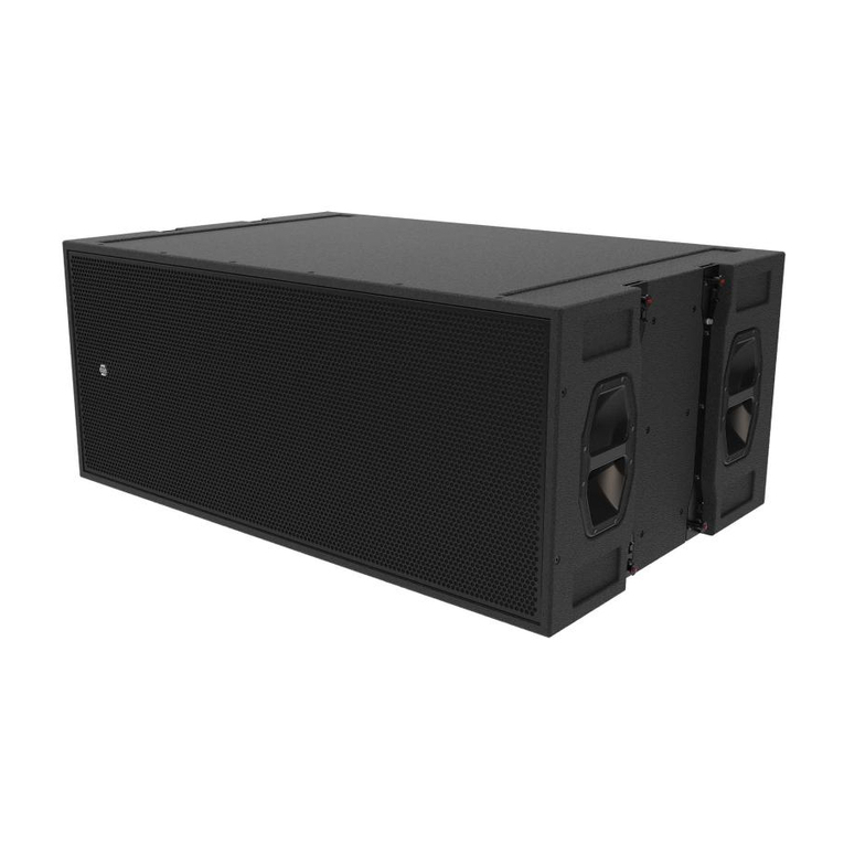
ST-215
Medium format touring subwoofer
FEATURES & BENEFITS
•Signature EM Acoustics “maximum headroom” design approach ensures
consistency of performance regardless of SPL level.
•Intuitive, simple 4-point flying system, assembled from ultra-high tensile
strength steel.
•Flying and stacking system allows assembly of cardioid arrays.
•Enclosure coated with 3-step polyurethane process - ensuring the cabinets
are not only weather resistant but more resilient to impact damage.
•Various features and accessories for easy moving & handling.
•Single amplifier channel required.
KEY SPECIFICATIONS
!
ENCLOSURE TYPE:
DRIVE UNITS:
FREQUENCY RESPONSE:
NOMINAL DISPERSION1:
MAXIMUM SPL:
NOMINAL IMPEDANCE:
DIMENSIONS (HxWxD):
NET/SHIPPING WEIGHT:
!
!
Medium format flyable reflex subwoofer
2 x 15” neodymium LF drive units
40Hz - 150Hz +/-3dB
omniirectional
133dB continuous, 139 dB peak
4 ohms
550 (21.7) x 772 (30.4) x 752 (29.6) mm/(ins)
73/77kg (161/169lbs)
FG-HALO-B
Master Flying Grid
The FG-HALO-B is the master flying grid for the both the ST-215 the HALO-B
system and provides a means of safely and swiftly flying arrays of ST-215
subwoofers. Up to 9 ST-215 subwoofers can be safely flown in any
configuration with a safety factor of 10:1. The FG-HALO-B is supplied with
two pickup links to use as suspension points - it is strongly recommended that
arrays larger than four subwoofers use two lifting points for control and ease
of use.
The FG-HALO-B can also be used as a means of ground stacking HALO-B on
top of ST-215 subwoofers.
The FG-HALO-B is supplied with four 2t WLL bow shackles.
Weight (without shackles) 32.5kg / 71.5lbs
Weight (including supplied shackles) 33.9kg / 74.6lbs
GS-HALO-B
Ground Stack Plate
The GS-HALO-B is a simple plate designed for ground stacking small HALO-
B arrays on stages, or larger arrays on top of ST-215 subwoofers. M8
locking knobs secure the GS-HALO-B to the ST-215 for neat arrays of up to
6 HALO-B elements. The GS-HALO-B can also be used as a neat base plate
when using HALO-B as a front-fill enclosure.
In installation applications, the GS-HALO-B can be used to mount pairs or
single elements from ceilings if required.
Weight 10.8kg / 23.8lbs

Page
8
of
57
ST-215 User Manual
v2 November 2019
CHAIN-HALO-B
Extension Lift Chain
The CHAIN-HALO-B assembly is intended to go between a motor and
the FG-HALO-B or CG-HALO-B pickup link. It is a variable length chain,
intended to give extra vertical clearance to accommodate motor lift
chain bags. It has a SWL of 760kg and an effective maximum working
length of 1000mm.
Weight 1.7kg / 3.6lbs
The SAFETY-HALO-B assembly is a 2-leg bridle chain assembly,
intended to connect the two safety points on the FG-HALO-B or CG-
HALO-B to a single point for application of a secondary safety. It has
an effective working length of 510mm and the following SWL:
2 tonne 0-45 degrees
1.4 tonne 45-60 degrees
The angle between the chain legs must not exceed 60 degrees.
Weight 1.6kg / 3.5lbs
WC-T215
Transit Wheelcart
Designed to safely transport columns of up to three ST-215 subwoofers
ready to fly, the WC-T215 is a steel frame construction wheelcart that
allows the ST-215 to lock securely to it.
Subwoofers can be assembled in cardioid arrays as well as front-facing,
and the WC-T215 is sized to fit three-wide across a standard width truck.
Four individually braked castors and protective polymer bumpers
complete the touring package.
Weight 26.7kg / 58.7lbs
Padded transit covers
Three padded transit cover options are available for the ST-215:
TC-T215 single subwoofer cover, designed to protect individual units
when fitted with the optional castor set.
TC-T215-2 dual subwoofer cover, designed to protect pairs of ST-215
subwoofers when on the WC-T215 wheelcart.
TC-T215-3 triple subwoofer cover, designed to protect three ST-215
subwoofers when on the WC-T215 wheelcart.
SAFETY-HALO-B
Chainset
Castor Set
For single subwoofer transport, tour-grade castors can be fitted to the
rear of the enclosure to allow the ST-215 to be easily moved around.

Page
9
of
57
ST-215 User Manual
v2 November 2019
3.0 – Simulation
Ease Focus 3
For safety and acoustic reasons, it is advised that users familiarize themselves with Ease Focus 3.
Along with providing the user with accurate simulations for setting up ST-215 subwoofers, it also
provides importing safety information with regards to load limits.
Ease Focus 3 can be downloaded for free from the AFMG website at http://focus.afmg.eu and is
currently available as a stand-alone application for Windows (XP or Higher) only. It can also be
downloaded directly from the EM Acoustics website with all the current product files embedded.
Tutorials for Ease Focus 3 are available from with the application itself.
For training on the design and implementation of ST-215 subwoofers including the specific use of
Ease Focus 3, please contact your local distributor.

Page
10
of
57
ST-215 User Manual
v2 November 2019
4.0 - Safety Considerations
System Overview
The flying system for the ST-215 has been specifically designed to be flexible, intuitive and reliable.
Please read this section of the user manual extremely carefully as the rigging of loudspeakers is a
very serious matter with potentially fatal consequences should anything go wrong. If you are in
ANY DOUBT WHATSOEVER, contact a reputable rigging company or your local EM Acoustics
representative.
IMPORTANT SAFETY CONSIDERATIONS
The ST-215 rigging system has been designed and constructed to a very high standard of safety,
and tested to demanding specifications. To ensure the highest standards of safety, the following
information on array assembly must be exactly followed and understood.
Only use EM Acoustics recommended rigging hardware and accessories, which are specifically
designed for the purpose. Do not use ST-215 flying hardware for any other loudspeaker system –
the components are specifically designed to work with the ST-215 product and are not
interchangeable with any other EM Acoustics loudspeaker product or any other loudspeaker system
unless clearly specified. The use of ST-215 flying hardware with other manufacturers’ systems may
compromise the safety standards and EM Acoustics is in no way liable for any loss, damage or injury
caused by such practice.
Do not modify or alter the ST-215 hardware or accessories, nor use them in any way other than that
described in this manual. Rigging components supplied as part of the ST-215 system are in no way
interchangeable and should not be used as such.
The component parts of the ST-215 rigging assembly should only be assembled in the manner
described in this manual, using the fasteners and fixings stated herein. The use of fasteners and
methods of assembly not described in this manual may result in an unsafe assembly and as such
EM Acoustics will not be responsible for any loss, damage or injury caused by such practice. Welding,
drilling or any other means of modifying any part of the flying hardware or permanently fixing
components to each other is strictly forbidden.
Rigging assemblies must only be assembled using the appropriate parts and fixings as described in
this manual, explicitly following the assembly instructions given herein. Rigging components must
only be fixed to EM Acoustics ST-215 subwoofers, using the correct cabinet location points,
assembly methods and fasteners specifically described within this manual.
Walls, floors and ceilings must be capable of supporting the actual load placed upon them. The
rigging hardware must be safely and securely fixed to both the loudspeaker system and the
supporting structure.

Page
11
of
57
ST-215 User Manual
v2 November 2019
Secondary Safeties
It is imperative that all loudspeakers flown in any given environment should be provided with a
second, independent and properly rated safety suspension point in addition to the principle load
bearing means of suspension. Steel wire ropes or steel chains of an approved construction and load
rating only may be used as secondary safeties. Plastic covered steel chains may not be used as
secondary safeties under any circumstances. Also ensure that all local and national laws are
complied with when determining your primary and secondary suspension points.
Safety Inspections
Carefully inspect all flying system components prior to use for defects or signs of damage prior to
assembling a HALO Arena array. If any components damaged or you suspect them to be damaged,
DO NOT USE THEM.
Regular scheduled tests – which are much more rigorous than visual inspections – of all rigging
components must also be carried out. Safety legislation, and test/inspection requirements, will vary
from country to country and as such it is the user’s responsibility to ensure that local regulations
are adhered to. In most cases, annual independent tests & inspections carried out by a suitably
approved and qualified inspector will be required.
EM Acoustics recommends detailed logbooks be kept of all inspections and load tests to ensure an
accurate record is kept of the testing for each EM Acoustics rigging accessory.
When flying any loudspeaker system, always wear protective headwear, footwear and eye
protection in accordance with local regulations.
The rigging of a flown loudspeaker system may be dangerous if not undertaken by a suitably
experienced and qualified rigger. Installation & fixing of all hanging points should only be
carried out by a professional rigger in accordance with local legislation as well as the rules of
the venue. The house rigger and/or venue manager must always be consulted.

Page
12
of
57
ST-215 User Manual
v2 November 2019
5.0 – Rigging System Overview
5.1 – ST-215 Cabinet Hardware Overview
[2]
[4]
[6]
[1]
[3]
[5]
[7]
[8]
1
Lifting & Carrying Handle
2
Rigging Link (retracted)
3
Rigging Link Lock Pin
4
Enclosure Link Pin
5
Floor Runner
6
Stacking Recess
7
M20 Threaded Polemount
8
M8 Threaded Fitting

Page
13
of
57
ST-215 User Manual
v2 November 2019
5.2 - FG-HALO-B
[6]
[1]
[3]
[4]
[8]
[7]
[9]
[11]
[12]
[6]
[4]
[2]
[2]
[4]
[4]

Page
14
of
57
ST-215 User Manual
v2 November 2019
[1] – Front Link Attachment Point
[2] – Rear Link Attachment Point
[3] – Splay Link Attachment Point
[4] – Sub Link Attachment Point
[5] – Cable Pick
[6] – Safety Points
[7] – Inclinometer Mounting Point
[8] – Inclinometer Laser Aperture
[9] – Pickup Link Location Holes
[10] – Pickup Links (Stowed)
[11] – Pickup Links (Full Position)
[12] – Pickup Links (Half Position)
This clevis forms the area where HALO-B or ST-215
enclosure front links should be engaged. A 0.313” ball-
lock pin secures each link in place.
This clevis forms the area where ST-215 subwoofer
rear links should be engaged. A 0.313” ball-lock pin
secures each link in place.
This location is only used for flying HALO-B enclosures
– please refer to the HALO-B user manual for full details.
A secondary safety must always be used on flown
arrays. Both safety points should be connected to avoid
the array swinging in the event of a primary lift failure.
The SAFETY-HALO-B 2-leg bridle is designed for this
purpose.
A range of laser inclinometers can be fitted to the FG-
HALO-B including TEQSAS devices. An aperture is
provided in the front beam for the laser to pass through.
The retractable cable pick gives a location to safely
secure the array cables at the back of the FG-HALO-B
grid. It can be stowed away when not being used.
Opening in the front grid load member for the
inclinometer laser beam to pass through.
Stow locations for the two pickup links when the FG-
HALO-B is being used for ground stack, or being stored
or transported.
When using a single pick point, reference Ease Focus 3
for the pick point for the desired angle. For a full
position, line up the white arrow with the number on
the spine
When using a single pick point, reference Ease Focus 3
for the pick point for the desired angle. For a half
position, line up the red arrow between the appropriate
numbers on the spine
Holes are numbered 1 to 39, the appropriate locations
are determined by your EASE Focus simulation. Links
must be secured with the two 0.375” ball-lock pins
attached.
When attaching an FG-HALO-B between ST-215
subwoofers and HALO-B enclosures, four rotating links
at the top of the grid in each corner engage into the
bottom of the subwoofer.

Page
15
of
57
ST-215 User Manual
v2 November 2019
FG-HALO-B Instruction Label – Spine, Left side

Page
16
of
57
ST-215 User Manual
v2 November 2019
FG-HALO-B Instruction Label – Spine, Right side

Page
17
of
57
ST-215 User Manual
v2 November 2019
FG-HALO-B Instruction Label – Side

Page
18
of
57
ST-215 User Manual
v2 November 2019
5.6 - GS-HALO-B
[1] – Front Link Attachment Point
[2] – Splay Link Attachment Point
[3] – ST-215 Attachment Point
[4] – M8 lobe knob
[5] – Installation Points
[3]
``
[5]
``
[1]
``
[2]
``
This clevis forms the area where HALO-B enclosure
front links should be engaged. A 0.313” ball-lock pin
secures each link in place.
The splay link of the first HALO-B enclosure should
engage in this slot in the spine. Pay attention to the
label details with regards the indicated angle compared
to actual angle for the first element in the array.
Three M8 clearance holes are provided in the GS-HALO-
B surface to secure it to an ST-215 subwoofer in ground
stack use. Use the three supplied M8 lobe knobs.
Three M8 lobe knobs to secure to an ST-215. These
knobs are stowed in the captive threaded bushes at the
rear of the GS-HALO-B.
For permanent installation of HALO-B enclosures, five
11mm diameter mounting holes are provided in the GS-
HALO-B surface.
[4]
``
[5]
``
[5]
``

Page
19
of
57
ST-215 User Manual
v2 November 2019
6.0 – System Setup
6.1 – Preparing ST-215 subwoofers for flying or stacking
6.1.1 – Extending the rigging links
Remove the Link Lock pin from
the top of each rigging assembly
Extend all four rigging links
Reinstate all four Link Lock pins to lock link in place
Safety label visible when link is retracted
Safety label hidden when link is correctly extended
Step 1.
Step 2.
Step 3.

Page
20
of
57
ST-215 User Manual
v2 November 2019
Standard subwoofer column
All subwoofers forward
Cardioid subwoofer column
One subwoofer in three reversed
6.1.2 – Cardioid Use
The ST-215 rigging locations are symmetrical front-to-back, so subwoofers can be
reversed to create cardioid arrays. Simply assemble the subwoofer stack or flown column
as normal but reverse every third subwoofer. The rigging hardware can and should be
engaged as normal.
For guidance on correct cabling for cardioid subwoofer arrays, see Chapter 7 of this manual.
IMPORTANT NOTE:
If flying a cardioid column of subwoofers and suspending from a single point on the
FG-HALO-B flying grid, consult EASE Focus 3 for the most suitable pickup point to use
to ensure the column hangs straight.
For all sections of this manual describing flying or stacking ST-215 subwoofers, the
procedure is identical when assembling cardioid subwoofer arrays.
Table of contents
Other EM Acoustics Subwoofer manuals

EM Acoustics
EM Acoustics Quake MSE-118 User manual

EM Acoustics
EM Acoustics ST-218 Operational manual

EM Acoustics
EM Acoustics EMS-115 User manual
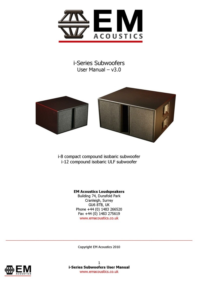
EM Acoustics
EM Acoustics S-18 Operational manual

EM Acoustics
EM Acoustics S-48 Operational manual

EM Acoustics
EM Acoustics EMS-215 User manual

EM Acoustics
EM Acoustics i-8 User manual
EM Acoustics
EM Acoustics EMS-112 User manual
EM Acoustics
EM Acoustics EMS-118 User manual
EM Acoustics
EM Acoustics S-218 User manual