EM Acoustics S-218 User manual

S-218 Subwoofer
Product User Manual
v1 November 2019
LOUDSPEAKERS REDEFINED

Page
2
of
25
S-218 User Manual
v1 October 2019
Contents
DECLARATION OF CONFORMITY ................................................................................................................4!
1.0 - Introduction ............................................................................................................................................. 5!
Unpacking.......................................................................................................................................................5!
2.0 – S-218 Subwoofer .................................................................................................................................. 6!
S-218 ...............................................................................................................................................................6!
3.0 – Simulation................................................................................................................................................. 7!
Ease Focus 3 .................................................................................................................................................7!
4.0 - Safety Considerations..........................................................................................................................8!
General Considerations in use................................................................................................................8!
Personal Injury.........................................................................................................................................8!
Ground Stacking......................................................................................................................................8!
Rigging and Suspension.......................................................................................................................9!
Material Damage from Magnetism ...................................................................................................9!
5.0 – Loudspeaker Hardware..................................................................................................................... 10!
5.1 – S-218 Cabinet Hardware Overview......................................................................................... 10!
5.2 – Stacking S-218 subwoofers....................................................................................................... 11!
5.5 – Fitting castors ................................................................................................................................. 12!
5.6 – Cardioid Use................................................................................................................................. 13!
6.0 – Powering the System........................................................................................................................ 14!
6.1 - Amplifier and Processing Requirements............................................................................... 14!
6.1.1 - Connections............................................................................................................................. 14!
6.1.2 - Connector Options................................................................................................................. 14!
6.1.3 – Amplifier Requirements ...................................................................................................... 15!
6.1.4 – Processing Requirements................................................................................................... 15!
6.2 - Presets and Settings .................................................................................................................... 16!
6.2.1 – Standard S-18 Preset........................................................................................................... 16!
6.2.2 – Cardioid Array Preset............................................................................................................ 16!
6.2.3 - Geometric Delay..................................................................................................................... 17!
6.2.4 - Applying EQ.............................................................................................................................. 17!
6.3 - Use with the DQ Series Advanced System Amplifiers ..................................................... 18!
6.3.1 - Connections............................................................................................................................. 18!
6.3.2 - Preset Recall............................................................................................................................ 18!

Page
3
of
25
S-218 User Manual
v1 October 2019
6.4 - System Connectivity..................................................................................................................... 19!
6.4.1 - Cable Length and Specification........................................................................................ 19!
7.0 – Servicing Information........................................................................................................................ 20!
7.1 – S-218/ST-218: Removing the grille....................................................................................... 20!
7.2 – S-218/ST-218: Removing the drive units ........................................................................... 21!
Appendix A – Technical Specifications.................................................................................................. 22!
S-218 large format flyable subwoofer............................................................................................. 22!
Appendix B – Technical Drawings ........................................................................................................... 23!
Appendix C – Spare Parts List ................................................................................................................... 24!
Appendix D – Warranty Information ....................................................................................................... 25!
Limited Warranty ................................................................................................................................. 25!
Warranty Coverage ............................................................................................................................. 25!
Returning your EM Acoustics loudspeaker................................................................................. 25!

Page
4
of
25
S-218 User Manual
v1 October 2019
DECLARATION OF CONFORMITY
The products contained within this manual conform to the
requirements of the EMC Directive 89/336/EEC, amended by
92/31/EEC and to the requirements of the Low Voltage Directive
73/23/EEC amended by 93/68/EEC.
EMC Emission EN55103-1:1996
Immunity EN55103-2:1996
Electrical Safety EN60065:1993
RECYCLING
This product and its packaging constitute the applicable product according
to the WEEE directive. Please ensure that at the end of the working life of
this product, it is disposed of sensibly in accordance with local and national
recycling regulations. The packaging supplied with this product is
recyclable. Please retain all packaging, however if disposing of this
packaging please ensure that you comply with local recycling regulations.
These products also all comply to the RoHS Directive 2002/95/EC.

Page
5
of
25
S-218 User Manual
v1 October 2019
1.0 - Introduction
Thank you for purchasing the S-218 subwoofer from EM Acoustics. This product has been
designed and rigorously tested to give you the utmost in sonic performance and many
years of reliable, trouble-free operation. Please take the time to read this user manual
thoroughly to ensure you get the best performance from your system and to ensure you
set it up correctly and safely. If you have any questions or are in any doubt whatsoever
about any aspect of your new product, please do not hesitate to contact us directly or your
local EM Acoustics representative.
The S-218 is a high-power reflex subwoofer, intended for a wide variety of low frequency
applications in medium to large applications. The S-218 is equally at home in permanent
installations as well mobile applications due to its rugged construction. A pair of state-of-
the-art 18” high-excursion neodymium drive units allows a surprising amount of SPL and
low frequency extension from a compact and lightweight cabinet.
This manual contains all the information you should need on topics of set up, amplifier
connection and basic service. If you feel we have missed anything, or you have a question
not covered by this manual, please visit our website www.emacoustics.co.uk and send us
a message or give us a call – we’re only too happy to help.
Unpacking
Please take care when unpacking your loudspeaker system. Once unpacked, please inspect
each enclosure thoroughly for any transit damage and in the case of any damage please
notify your carrier immediately. It is the responsibility of you, the consignee, to instigate
any claim. Please retain all original packaging in case of future re-shipment.

Page
6
of
25
S-218 User Manual
v1 October 2019
2.0 – S-218 Subwoofer
S-218
High-power reflex subwoofer
FEATURES & BENEFITS
•Signature EM Acoustics “maximum headroom” design approach ensures
consistency of performance regardless of SPL level.
•Enclosure coated with 3-step polyurethane process - ensuring the cabinets
are not only weather resistant but more resilient to impact damage.
•Various features and accessories for easy moving & handling.
•Tour grade castor set included.
•Single amplifier channel required.
KEY SPECIFICATIONS
!
ENCLOSURE TYPE:
DRIVE UNITS:
FREQUENCY RESPONSE:
NOMINAL DISPERSION1:
MAXIMUM SPL:
NOMINAL IMPEDANCE:
DIMENSIONS (HxWxD):
NET/SHIPPING WEIGHT:
!
!
High-power reflex subwoofer
2 x 18” neodymium LF drive units
28Hz - 150Hz +/-3dB
omniirectional
137dB continuous, 143 dB peak
2 ohms
550 (21.7) x 1300 (51.2) x 850 (33.5) mm/(ins)
106/108kg (233.2/237.6lbs)

Page
7
of
25
S-218 User Manual
v1 October 2019
3.0 – Simulation
Ease Focus 3
For acoustic reasons it is advised that users familiarize themselves with Ease Focus 3 – this system
provides the user with accurate simulations for setting up S-218 subwoofers.
Ease Focus 3 can be downloaded for free from the AFMG website at http://focus.afmg.eu and is
currently available as a stand-alone application for Windows (XP or Higher) only. It can also be
downloaded directly from the EM Acoustics website with all the current product files embedded.
Tutorials for Ease Focus 3 are available from with the application itself.
For training on the design and implementation of S-218 subwoofers including the specific use of
Ease Focus 3, please contact your local distributor.

Page
8
of
25
S-218 User Manual
v1 October 2019
4.0 - Safety Considerations
General Considerations in use
Loudspeaker systems are potentially dangerous objects if used incorrectly. Please ensure
that you read this section fully, and contact EM Acoustics or your local dealer should you
be in any doubt over correct operation procedures.
Personal Injury
Never stand in the immediate vicinity of loudspeakers when in use at high level.
Professional loudspeaker systems are capable of producing sound pressure levels which
can cause permanent damage to human hearing. Levels in excess of 90dB can cause
hearing damage if people are exposed to them over a long period of time, so care and
attention must be used for both staff and audience members.
When deploying loudspeaker systems on the ground or when flown, please take careful
note of the following important safety considerations:
• Only use accessories and flying hardware supplied or approved by EM Acoustics for
flying or transporting loudspeaker systems. Pay close attention to specific
instructions, especially those considering maximum load capabilities as detailed in
the appropriate user manuals or on the legend labels on the accessories
themselves.
• Ensure all additional accessories, fasteners and secondary safeties are of an
appropriate size, working load limit and safety factor.
• All loudspeakers and accessories should be regularly inspected for signs of wear
and tear, and any damaged parts should be replaced.
• All load bearing parts and assembly bolts on accessories should be regularly
checked to ensure they are tight and not worn.
Ground Stacking
• Ensure that the floor or stage surface can withstand the weight of the system.
• Wherever possible, avoid high stacks and use ratchet straps to secure loudspeakers
together. Please also remember that vibrations from subwoofer systems can shake
other loudspeakers out of place, which may present a toppling hazard. The use of
ratchet straps and non-slip material is recommended to prevent this.

Page
9
of
25
S-218 User Manual
v1 October 2019
Rigging and Suspension
Please see Chapter 5 for further information on the detailed rigging options for your
loudspeaker system.
WARNING: The overhead suspension of loudspeakers is a very serious issue with
potentially lethal consequences should anything go wrong. Rigging should only be
carried out by experienced personnel following safe working practice. Should you be
in any doubt whatsoever, please contact your local dealer who will be able to refer you
to a suitable rigging company.
Material Damage from Magnetism
Loudspeakers produce a static magnetic field at all times – even when not in use. Certain
devices are susceptible to external magnetism, and as such a safe distance should be
maintained to prevent damage. It is recommended that a safe distance of 0.5m (1.5ft) is
maintained from loudspeakers when stored, transported and in use, from devices such as
computer hard drives, magnetic media, bank cards to remove the risk of corruption. Larger
distances may be required for some older cathode ray tube displays.

Page
10
of
25
S-218 User Manual
v1 October 2019
5.0 – Loudspeaker Hardware
5.1 – S-218 Cabinet Hardware Overview
[3]
[1]
[6]
[2]
1
Lifting & Carrying Handle
2
Protective Floor Runner (Landscape)
3
Stacking recess (Landscape)
4
Protective Floor Runner (Portrait)
5
Locking recess
6
Castor attachment point
[4]
[5]

Page
11
of
25
S-218 User Manual
v1 October 2019
5.2 – Stacking S-218 subwoofers
The S-218 subwoofer has two
protective plastic runners on the
underneath, and matching recesses
in the top face of the cabinet. When
stacking S-18 subwoofers, this
provides a neat and clear way of
creating a tidy stack.
PLEASE BE AWARE THAT STACKS SHOULD ALWAYS BE PLACED ON LEVEL GROUND,
AND STRAPS OR SIMILAR SHOULD BE USED TO SECURE THEM.
There are also runners on one end to facilitate using the subwoofer end-up. S-218
subwoofers should
not
be stacked on top of each other in this way. The small recesses in
the opposite end are to ensure you can position stacks of landscape S-218 directly beside
each other.

Page
12
of
25
S-218 User Manual
v1 October 2019
Using a 5mm Allen key, remove the 16 M8 x 20
countersunk socket machine screws on the
rear panel. Ensure that all the threaded fittings
inside the cabinet are still intact and the
threads are clear before proceeding.
Fit each castor to the rear of the cabinet, ensuring
all four bolts are started in their threads before
tightening completely. The Form A (flat) washer
should be in contact with the castor frame, and the
spring washer should be between the flat washer
and the bolt head.
5.5 – Fitting castors
The S-218 is supplied with a set of four tour-grade castors which can be fitted for ease of
movement. The carton should contain:
4pcs 32 x 100mm heavy duty castor
17pcs M8 x 30 hex head set screw
17pcs M8 Form A (flat) washer
17pcs M8 spring washer
Step 1.
Step 2.
M8x30 hex head
set screw
M8 spring washer
M8 Form A washer

Page
13
of
25
S-218 User Manual
v1 October 2019
Standard subwoofer column
All subwoofers forward
Cardioid subwoofer column
One subwoofer in three reversed
5.6 – Cardioid Use
The S-18 feet and recess locations are symmetrical front-to-back, so subwoofers can be
reversed to create cardioid arrays. Simply assemble the subwoofer stack or flown column
as normal but reverse every third subwoofer. The stack of subwoofers should be secured
with ratchet straps or similar for safety.
For guidance on correct cabling for cardioid subwoofer arrays, see Section 6.2.2 of this
manual.

Page
14
of
25
S-218 User Manual
v1 October 2019
6.0 – Powering the System
The S-218 subwoofer can be powered from any amplifier & DSP combinations with the
relevant high & low pass filter, and limiter settings.However, due to the self-contained
nature of the package, the use of DQ Series advanced system amplifiers is highly
recommended. The use of DQ Series amplifiers provides a neat and flexible system that
will encompass all requirements for the system to function correctly, as well as providing
user control for room EQ and system alignment.
6.1 - Amplifier and Processing Requirements
6.1.1 - Connections
The S-218 requires only a single amplifier channel. Inputs to the S-218 enclosure are on
a single Neutrik SpeakON NL4 as illustrated below.
Two-core cable should be used for connecting S-218 subwoofers, and the connections are
as follows:
SpeakON connection 1+ 1- 2+ 2-
Drive unit connection LF + LF - N/C N/C
6.1.2 - Connector Options
The ST-218 is supplied as standard with a single NL4TMP connector, which forms an IP54
rated connection when used with the STX series of SpeakON cable connectors. For more
demanding environments, S-218s can be supplied with other options by special order –
please contact EM Acoustics to discuss your requirement.

Page
15
of
25
S-218 User Manual
v1 October 2019
6.1.3 – Amplifier Requirements
The S-218 is a very powerful subwoofer, making use of some of the most advanced drive
units available in the industry today. It is good practice to ensure that your amplifier can
deliver at least double the RMS power handling of the loudspeaker to ensure full headroom,
and as such the amplifier requirement is:
Product RMS Power Handling Recommended Min. Amplifier Power
S-218/ST-218 2500W @ 2 ohms 5000W @ 2 ohms
All of the DQ Series advanced system amplifiers can be used to power the S-218, however
the DQ6 and DQ10 are lower power models and as such will not provide maximum power
for the subwoofer.
The following table shows the maximum number of ST-218 that can be connected per
channel on the various different amplifiers:
Amplifier Max ST-218 per channel
DQ6 1*
DQ10 1*
DQ20 1
* - The DQ6 and DQ10 do not provide sufficient power for maximum headroom for the S-
218 and as such should only be used in lower SPL environments.
6.1.4 – Processing Requirements
The S-218 requires active high and low pass filters, and appropriate limiter settings. If not
using DQ Series amplifiers, or the DSC48 Digital System Controller, then a suitable DSP
system must be used in conjunction with your S-218 to prevent damage to the subwoofer.
Check the EM Acoustics website for the most up-to-date DSP settings for the S-218.

Page
16
of
25
S-218 User Manual
v1 October 2019
6.2 - Presets and Settings
6.2.1 – Standard S-18 Preset
S-218/ST-218 subwoofers require only a single amplifier channel, and as such the preset
recalled will only require one output from your DQ Series amplifier.
6.2.2 – Cardioid Array Preset
The S-218/ST-218 can be used to create cardioid arrays as detailed in chapter 6 by
ensuring that one in three subwoofers are physically reversed, and the appropriate S-
218/ST-218 Cardioid preset is loaded into the amplifier. This preset requires three
amplifier channels.

Page
17
of
25
S-218 User Manual
v1 October 2019
6.2.3 - Geometric Delay
Appropriate delay will need to be applied to account for physical location differences
between different elements of your system – for example time-aligning subwoofers to the
main system. The use of SMAART or similar can make this task a great deal simpler and
faster.
6.2.4 - Applying EQ
The presets are intended to be a starting point for your system and will almost certainly
require tuning on-site dependent on room characteristics, the rest of your system design
and the system voicing you are aiming for. The S-218 is designed with a significant
amount of system headroom, so applying EQ is perfectly acceptable.

Page
18
of
25
S-218 User Manual
v1 October 2019
The four amplifier channels appear on four
speakON connectors on the rear of the DQ Series
amplifiers. S-218 subwoofers require one
amplifier channel.
6.3 - Use with the DQ Series Advanced System Amplifiers
The S-218 will perform best when using DQ Series advanced system amplifiers, as not only are they
state-of-the-art amplifiers, but the onboard DSP provides appropriate high/low pass filter settings
and limiters to get the best from your subwoofers. Please refer to the DQ Series User Manual for
detailed information on using the amplifiers and the System Engineer software.
6.3.1 - Connections
6.3.2 - Preset Recall
The family of S-218 presets is pre-installed on the DQ amplifiers, and as such can be used
following the normal preset recall procedure. The S-218 and it’s flyable variant the ST-
218 utilise the same presets. The presets available are:
S-218.Sub Standard S-218/ST-218 subwoofer preset
S-218.Card Cardioid Array S-218/ST-218 subwoofer preset
As mentioned above, these presets are intended to be a starting point and additional work
may be required depending on the venue, the style of content and the end result you are
looking for.

Page
19
of
25
S-218 User Manual
v1 October 2019
6.4 - System Connectivity
6.4.1 - Cable Length and Specification
All cables add to the system impedance, and as such careful selection is required depending on your
amplifier setup and overall system impedance. Cables with a cross sectional area of less than
2.5mm2should not be used. Recommended maximum cable lengths are given below:
Conductor Area Maximum Recommended Cable Length
2 ohms 4 ohms 8 ohms
2.5mm2(14 AWG) 15m 30m 60m
4.0mm2(12 AWG) 20m 40m 80m
6.0mm2(10 AWG) 30m 60m 120m

Page
20
of
25
S-218 User Manual
v1 October 2019
7.0 – Servicing Information
All S-218 components can be removed for service purposes if required, using the minimum of tools.
DRAWINGS ILLUSTRATE THE ST-218 FLYABLE VERSION, BUT THE SERVICE DETAILS ARE
IDENTICAL BETWEEN THE S-218 AND ST-218.
7.1 – S-218/ST-218: Removing the grille
TOOLS REQUIRED: 4mm Allen key
1. Lie the enclosure on its’ back and remove the sixteen M6x30 countersunk socket screws using a 4mm
Allen key, and then lift the grille clear of the cabinet.
2. To replace the grille, position the grille on the front of the S-218 (logo badge should be on the left of
the enclosure when in a flown configuration) and ensure the threaded fittings on the grille are lined
up with the mounting holes. Replace each of the sixteen M6x30 countersunk bolts and ensure all
machine screws are started in their threads before beginning to tighten. Ensure they are all tightened
evenly so that the grille sits straight and flat and does not rattle.
Table of contents
Other EM Acoustics Subwoofer manuals
EM Acoustics
EM Acoustics EMS-118 User manual
EM Acoustics
EM Acoustics EMS-215 User manual
EM Acoustics
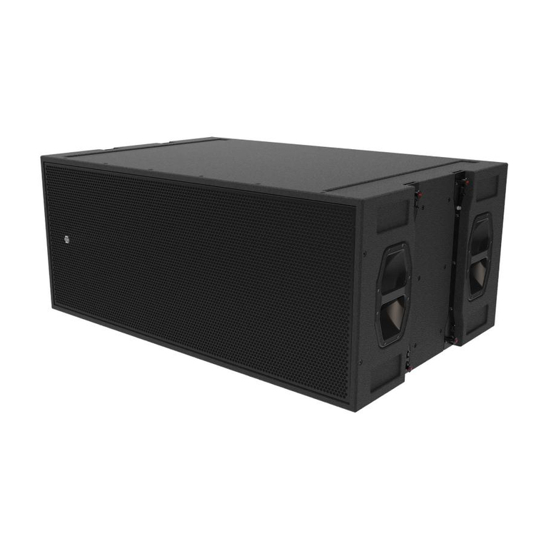
EM Acoustics ST-218 Operational manual
EM Acoustics
EM Acoustics EMS-115 User manual

EM Acoustics
EM Acoustics ST-215 Operational manual
EM Acoustics
EM Acoustics S-48 Operational manual
EM Acoustics
EM Acoustics i-8 User manual
EM Acoustics
EM Acoustics EMS-112 User manual
EM Acoustics
EM Acoustics S-18 Operational manual

EM Acoustics
EM Acoustics Quake MSE-118 User manual
