EMA PCM-9582 User manual

PCM-9582
Onboard Intel® Pentium M EBX
SBC with Audio, VGA, LCD,
SATA
User Manual

PCM-9582 User Manual ii
Copyright
This document is copyrighted, © 2006. All rights are reserved. The orig-
inal manufacturer reserves the right to make improvements to the prod-
ucts described in this manual at any time without notice.
No part of this manual may be reproduced, copied, translated or transmit-
ted in any form or by any means without the prior written permission of
the original manufacturer. Information provided in this manual is
intended to be accurate and reliable. However, the original manufacturer
assumes no responsibility for its use, nor for any infringements upon the
rights of third parties that may result from such use.
Acknowledgements
Award is a trademark of Award Software International, Inc.
VIA is a trademark of VIA Technologies, Inc.
IBM, PC/AT, PS/2 and VGA are trademarks of International Business
Machines Corporation.
Intel and Pentium are trademarks of Intel Corporation.
Microsoft Windows® is a registered trademark of Microsoft Corp.
RTL is a trademark of Realtek Semi-Conductor Co., Ltd.
ESS is a trademark of ESS Technology, Inc.
UMC is a trademark of United Microelectronics Corporation.
SMI is a trademark of Silicon Motion, Inc.
Creative is a trademark of Creative Technology LTD.
CHRONTEL is a trademark of Chrontel Inc.
All other product names or trademarks are properties of their respective
owners.
For more information on this and our other products, please visit
our website at: http://www.emacinc.com
For technical support and service, please visit our support website at:
http://www.emacinc.com/support
This manual is for the PCM-9582.
Part No. 2006958212
3rd Edition,
Jan 2006

iii
Packing List
Before you begin installing your card, please make sure that the following
materials have been shipped:
• 1 PCM-9582 all-in-one single board computer
• 1 CD disk for utility and drivers (p/n DSK-002 optional)
• 1 ATX power cable (p/n:1700001112)
• 1 Mini Jumper*10 PCS Package (p/n: 9689000002)
If any of these items are missing or damaged, contact your distributor or
sales representative immediately.
Model No. List Description
PCM-9582F-00A1 uFCPGA2 SKT478 w/LAN/
Audio/LVDS & optional CPU
PCM-9582FG-00A1 Same as PCM-9582F-00A1
w/GigaLAN & optional CPU
PCM-9582F-M0A1 Same as PCM-9582F-00A1
w/Celeron M 600 MHz 512 KB
PCM-9582F-S1A1 same as PCM-9582F-00A1
w/ Pentium M 1.1 GHz

PCM-9582 User Manual iv
FCC
This device complies with the requirements in part 15 of the
FCC rules: Operation is subject to the following two condi-
tions:
1.This device may not cause harmful interference, and
2. This device must accept any interference received, includ-
ing interference that may cause undesired operation
This equipment has been tested and found to comply with the
limits for a Class A digital device, pursuant to Part 15 of the
FCC Rules. These limits are designed to provide reasonable
protection against harmful interference when the equipment
is operated in a commercial environment. This equipment
generates, uses, and can radiate radio frequency energy
and, if not installed and used in accordance with the instruc-
tion manual, may cause harmful interference to radio commu-
nications. Operation of this device in a residential area is
likely to cause harmful interference in which case the user will
be required to correct the interference at his/her own
expense. The user is advised that any equipment changes or
modifications not expressly approved by the party responsi-
ble for compliance would void the compliance to FCC regula-
tions and therefore, the user's authority to operate the
equipment.
Caution!
!
There is a danger of a new battery exploding if it is incorrectly
installed. Do not attempt to recharge, force open, or heat the
battery. Replace the battery only with the same or equivalent
type recommended by the manufacturer. Discard used batter-
ies according to the manufacturer’s instructions.

v
Additional Information and Assistance
1. Visit the Dristibutators website at www.emacinc.com where you can
find the latest information about the product.
2. Contact your distributor, sales representative, or our customer
service center for technical support if you need additional assistance.
Please have the following information ready before you call:
• Product name and serial number
• Description of your peripheral attachments
• Description of your software (operating system, version, application
software, etc.)
• A complete description of the problem
• The exact wording of any error messages

PCM-9582 User Manual vi

vii
Contents
Chapter 1 Introduction ......................................................2
1.1 Introduction ....................................................................... 2
1.2 Features ............................................................................. 2
1.3 Specifications .................................................................... 3
1.4 Board layout: dimensions.................................................. 6
Figure 1.1:Board layout: dimensions (component side). 6
Figure 1.2:Board layout: dimensions (solder side)......... 7
Chapter 2 Installation ......................................................10
2.1 Jumpers............................................................................ 10
Table 2.1:Jumpers......................................................... 10
2.1.1 Jumpers setting drawing ............................................... 10
2.2 Connectors....................................................................... 12
Table 2.2:Connectors .................................................... 12
2.3 Locating jumpers and Connectors................................... 14
Figure 2.1:Jumper & Connector (component side) ...... 14
Figure 2.2:Jumper & Connector (solder side) .............. 15
2.4 Setting Jumpers ............................................................... 16
2.5 Clear CMOS (JP3) .......................................................... 17
2.6 Installing DIMMs............................................................ 17
2.7 IDE, CDROM hard drive connector (CN15) .................. 18
2.7.1 Connecting the hard drive............................................. 18
2.8 Solid State Disk............................................................... 18
2.8.1 CompactFlash (CN30) .................................................. 18
2.9 Floppy drive connector (CN14) ...................................... 19
2.9.1 Connecting the floppy drive ......................................... 19
2.10 Parallel port connector (CN16) ....................................... 20
2.11 Keyboard and PS/2 mouse connector (CN27) ................ 20
2.12 Front Panel Connector (CN22) ....................................... 20
2.12.1 Power & HDD LED (pin 1-4 of CN22)........................ 20
2.12.2 Reset switch (pin 13-14 of CN22) ................................ 20
2.13 Power connectors (CN25,CN5)....................................... 21
2.13.1 ATX power connector, +5V (CN5) .............................. 21
2.13.2 CPU Fan power supply connector (CN25)................... 21
2.14 ATX power ON/OFF switch con. pin 11-12 of CN22 .... 21
2.14.1 ATX feature (CN5) & soft power switch (CN22) ........ 21
2.15 Audio AC'97 Link interfaces (CN4) ............................... 21
2.15.1 Audio connector(CN4) ................................................. 21
2.15.2 CD audio-in connector (CN3)....................................... 21
2.16 COM port connector (CN21) .......................................... 22

PCM-9582 User Manual viii
2.17 VGA/LVDS interface connections (CN7, CN8,CN9) .... 22
2.17.1 CRT display connector (CN7) ...................................... 22
2.17.2 LVDS LCD panel connector (CN8) ............................. 22
2.17.3 DVI LCD panel connector(CN9).................................. 22
2.18 TV-out interface (CN2).................................................. 23
2.19 Ethernet configuration (CN11, CN23) ............................ 23
2.19.1 100Base-T connector (CN11, PCM-9582) ................... 23
2.19.2 Network boot ................................................................ 23
2.20 USB connectors (CN18,CN20) ....................................... 24
2.21 LCD Backlight connector (CN1) .................................... 24
2.22 SATA Connector (CN23, CN24) .................................... 24
2.23 DI/O connector (CN19)................................................... 24
2.24 -12V and -5V connector (CN6)....................................... 24
2.25 Extension SMBUS connector (CN26) ............................ 24
Chapter 3 Software Configuration .................................26
3.1 Introduction ..................................................................... 26
3.2 Connections to Three Standard LCDs............................. 27
3.2.1 LG LM150X06 (1024x768(16 colors) LVDS LCD).... 27
Chapter 4 Award BIOS Setup.........................................30
4.1 System test and initialization........................................... 30
4.1.1 System configuration verification................................. 30
4.2 Award BIOS setup .......................................................... 31
4.2.1 Entering setup ............................................................... 31
Figure 4.1:BIOS setup program initial screen .............. 31
4.2.2 Standard CMOS Features setup.................................... 32
Figure 4.2:CMOS Features setup.................................. 32
4.2.3 Advanced BIOS Features setup .................................... 33
Figure 4.3:Advanced BIOS Features setup................... 33
4.2.4 Advanced Chipset Features setup ................................. 34
Figure 4.4:Advanced Chipset Features setup ............... 34
4.2.5 Integrated Peripherals ................................................... 34
Figure 4.5:Integrated Peripherals.................................. 34
4.2.6 Power Management Setup ............................................ 35
Figure 4.6:Power Management Setup........................... 35
4.2.7 PnP/PCI Configurations................................................ 35
Figure 4.7:PnP/PCI Configurations .............................. 35
4.2.8 PC Health Status ........................................................... 36
Figure 4.8:PC Health Status.......................................... 36
4.2.9 Frequency/Voltage Control........................................... 37
Figure 4.9:Frequency/Voltage Control ......................... 37
4.2.10 Load Optimized Defaults.............................................. 38
Figure 4.10:Load Optimized Defaults .......................... 38
4.2.11 Set Password ................................................................. 38

ix
4.2.12 Save & Exit Setup......................................................... 40
4.2.13 Exit Without Saving...................................................... 40
Chapter 5 PCI Graphic Setup.........................................42
5.1 Introduction ..................................................................... 42
5.1.1 Chipset .......................................................................... 42
5.1.2 Display memory............................................................ 42
5.1.3 Display types................................................................. 42
5.1.4 Dual/Simultaneous Display .......................................... 42
5.2 Installation of the PCI Graphic driver............................. 45
5.2.1 Installation for Windows 98/ME/2000/XP ................... 45
5.3 Further Information ......................................................... 47
Chapter 6 Audio Setup.....................................................50
6.1 Introduction ..................................................................... 50
6.2 Driver installation............................................................ 50
6.2.1 Before you begin........................................................... 50
Chapter 7 PCI Bus Ethernet Interface...........................54
7.1 Introduction ..................................................................... 54
7.2 Features ........................................................................... 54
7.3 Installation of Ethernet Driver......................................... 54
7.3.1 Installation for Windows 98 & 2000 ............................ 55
7.4 Further information ......................................................... 62
Appendix A Prog. GPIO & W’dog Timer.........................64
A.1 Supported GPIO Register................................................ 64
A.1.1 GPIO Registers ............................................................. 64
A.1.2 GPIO Example program-1 ............................................ 65
A.2 Watchdog programming.................................................. 67
Appendix B Pin Assignments .............................................70
B.1 CPU fan connector (CN25) ............................................. 70
B.2 Ethernet 10/100Base-T Connector (CN11)..................... 71
B.3 Audio connector (CN4)................................................... 72
B.4 CD-IN Connector (CN3)................................................. 72
B.5 Power input Connector (CN5)......................................... 73
B.6 Keyboard and PS/2 Mouse Connector (CN27) ............... 73
B.7 Floppy Disk Drive Connector (CN14) ............................ 74
B.8 IDE Hard Drive Connector (CN15) ............................... 75
B.9 Parallel Port Connector (CN16) ...................................... 76
B.10 Front Panel LED (CN22) ............................................... 77
B.11 USB Connector (CN18,20) ............................................. 77
B.12 TV Out Connector (CN2)................................................ 78
B.13 LCD Inverter Backlight Connector (CN1)...................... 79
B.14 CRT Display Connector (CN7)....................................... 79

PCM-9582 User Manual x
B.15 LVDS Connector (CN8) ................................................. 80
B.16 COM Port Connector (CN21) ........................................ 81
B.17 CompactFlash Card Connector (CN30) .......................... 82
B.18 Mini PCI Connector(CN29)............................................ 83
Appendix C System Assignments ......................................86
C.1 System I/O Ports.............................................................. 86
Table C.1:System I/O Ports .......................................... 86
C.2 1st MB memory map....................................................... 87
Table C.2:1st MB memory map ................................... 87
C.3 DMA channel assignments.............................................. 87
Table C.3:DMA channel assignments .......................... 87
C.4 Interrupt assignments ...................................................... 88
Table C.4:Interrupt assignments ................................... 88
Appendix D Optional Extras ..............................................90
D.1 PCM-10586-6200 Cable kit for PCM-9582................... 90
Table D.1:PCM-10586-6200 wiring kit 9582............... 90
D.2 ATX Power Control Cable (CN15)................................. 90
Appendix E Mechanical Drawings.....................................92
Figure E.1:PCM-9582 Mechanical Drawing (component
side)...................................................................92
Figure E.2:PCM-9582 Mechanical Drawing (solder side)
...........................................................................93

1 Chapter1
CHAPTER
1
General Information
This chapter gives background
information on the PCM-9582.
Sections include:
• Introduction
• Features
• Specifications
• Board layout and dimensions

PCM-9582 User Manual 2
Chapter 1 Introduction
1.1 Introduction
The PCM-9582 series is a 5.25” SBC (Single Board Computing)
designed with powerful Intel Pentium M or Celeron M processor, with
Intel 855GME and 6300ESB chipset, which supports enhanced Intel
"SpeedStep" technology and Dynamic Video Memory Technology For
maximum performance, PCM-9582 also supports one 184 PIN DIMM
socket that ECC DDR memory up to 1GB. These chipsets are specifically
for embedded computing and provide an optimized on-board integrated
graphics solution. "SpeedStep" technology intelligently focuses system
power where the CPU needs it and automatically regulates power usage
to preserve battery life.
Other on-board features include 2 EIDEs, 2 SATAs, 1 FDD, 1 LPT, 4
USB2.0s, 4 serial ports(3 x RS-232 and 1 x RS-232/422/485), PS/2 Key-
Board/mouse, watchdog.. The SSD solution supports Type I/II Compact-
Flash cards.
The PCM-9582 complies with EBX form factor (Embedded Board
eXpandable). It is small enough for embedded applications, yet large
enough to contain the functions of a full embedded computer system. The
EBX system expansion is based on popular existing industry standards-
PC/104TM, PCI, PC/104-PlusTM, and PCMCIA, hence the PC/104-Plus
interface on PCM-9582 brings the advantages of the wide variety of
embedded system oriented expansion modules. The expandability can
also be fulfilled by the MiniPCI socket on the solder side.
1.2 Features
• Embedded Intel Pentium M 1.1G/Intel Celeron M 600 MHz
• Support ECC DDR Memory
• Applied EBX form fator standard and support PC/104-Plus bus
• Support up to 1000Base-T Ethernet
• Support 4 port Host USB2.0
• Supports up to 2 channel 48-bit LVDS interface
• Supports Enhanced Intel® Speedstep Technology

3 Chapter1
1.3 Specifications
Standard SBC Functions
• CPU: Supports onboard Intel® Pentium® M and Celeron® M or
socket478
• BIOS: Award 512K byte Flash memory
• System memory: One 184 pin DIMM sockets, support ECC
Double Data Rate (DDR)128 MB to 1 GB, accepts 128/256/512/1000
MB DDR200/266/333 DRAM.
• System chipset:Intel 855GME GMCH/6300ESB Chipset 400MHz
FSB
• 2nd cache memory: Depends on CPU type from 512 KB to 2 MB
• Enhanced IDE interface: One Enhanced IDE interfacesupports 2 IDE
devices. PIO mode 3 or mode 4, Ultra DMA 100 tranfer. 2 Serial ATA
standard connector to support SATA 150
• FDD interface: Supports one FDD
• Serial ports: Three serial RS-232 ports, one serial RS-232/422/485
ports
• Parallel port: One parallel port, supports SPP/EPP/ECP mode
• Keyboard/mouse connector: Supports standard PS/2 keyboard and a
PS/2 mouse
• Power management: APM Rev. 1.2 compliant power management
ACPI support
• Watchdog timer: Winbond W83627, 255 levels timer interval, setup
by software
• USB: Four USB 2.0 compliant host ports
• IrDA: N/A
• GPIO: 8-bit general purpose input/output
• Expansion: PC/104(LPC), PC/104+, PCI and miniPCI

PCM-9582 User Manual 4
Solid State Disk
• Supports one 50-pin socket for CFC type I/II
VGA/LCD Interface
• Chipset: Intel Montara-GM/GM+ GMCH
• Frame buffer: Optimized Shared Memory Architecture, support up to
64MB frame buffer using system memory
• Interface: 4x AGP VGA/LVDS interface
• Display mode: CRT Modes: pixel resolution up to 1600 x 1200 at 85-
Hz and 2048 x 1536 at 75-Hz
• LCD mode: Dual channel LVDS panel support up to UXGA panel res-
olution with frequency range from 25-MHz to 112-MHz
• LVDS: Support 2 channel (48-bit) LVDS LCD panel
TV-Out/DVI
• Chipset: Chrontel CH7009
• Supports composite, s-video or RGB output
• Support NTSC and PAL formats
Ethernet interface
• Chipset:
• Intel 82551ER /82551QM optional (PCM-9582F)
• Intel 82541GI (PCM-9582FG)
• Ethernet interface:
• IEEE 802.3u 100 BASE-T Fast Ethernet compatible (PCM-9582F)
• IEEE 802.3 z/ab 1000 BASE-T Gigabit Ethernet compatible (PCM-
9582FG)
• I/O address switchless setting
• Built-in boot ROM
Audio Function
• Chipset: 6300ESB, Audio codec ALC 202
• Audio controller: AC’97 3D surround stereo sound

5 Chapter1
• Supports Speaker out, CD-input, Line-in, Line-out, Microphone
Mechanical and Environmental
• Dimensions: (L x W)203 x 146 mm (8" x 5.75")
• Power supply Voltage:ATX, with Vcore 2 phase, +5V power only can
work
• Power Requirement: (Celeron M 600 with 256MB)
Max: 2.63A@ 5V, 0.04 A @ 12V
Typical: 2.1A@ 5V, 0.03A @ 12V
(Pentium M 1.1G with 256MB)
Max (HCT): 3.1A @ 5V, 0.15A @ 12V
Typical: 2.3A @ 5V, 0.13A@12V
(Pentium M 1.6G with 256MB)
Max (HCT): 4.8A @ 5V, 0.15A@ 12V
Typical: 2.54A @ 5V, 0.14A@12V
• Operating temperature:0 ~ 60° C (32~140° F)
• Operating Humidity:0% ~ 90% Relative Humidity, non-condensing
• Weight: 0.85 kg (weight of total package)
PCM-9582 User Manual 6
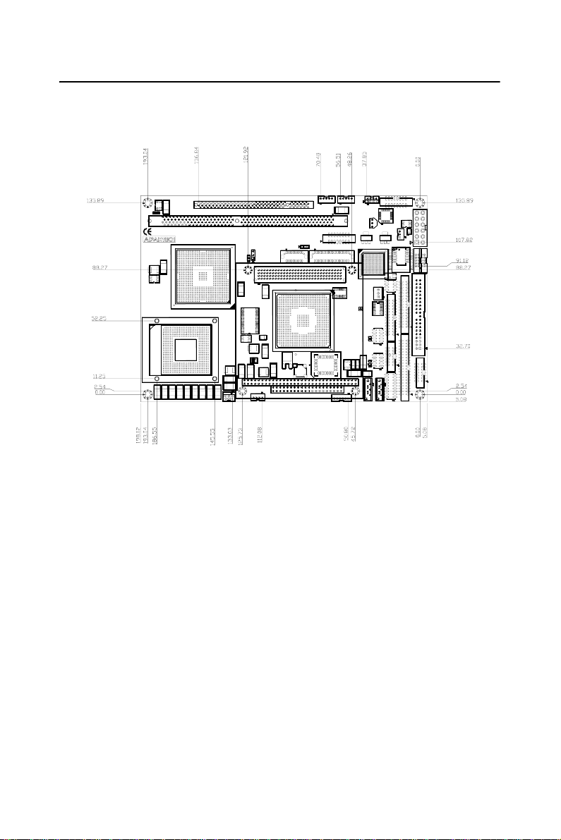
1.4 Board layout: dimensions
Figure 1.1: Board layout: dimensions (component side)
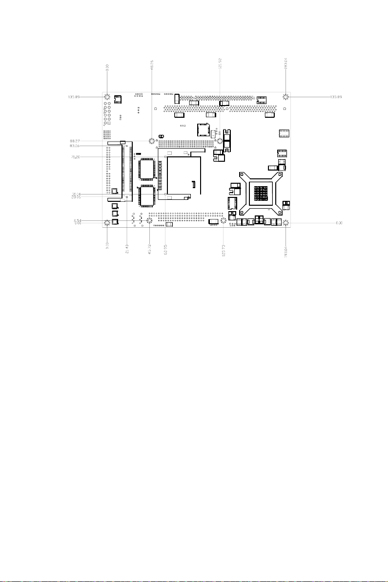
7 Chapter1
Figure 1.2: Board layout: dimensions (solder side)

PCM-9582 User Manual 8

9 Chapter2
CHAPTER
2
Installation
This chapter explains the setup proce-
dures of PCM-9582 hardware, includ-
ing instructions on setting jumpers and
connecting peripherals, switches and
indicators. Be sure to read all safety
precautions before you begin the instal-
lation procedure.
PCM-9582 User Manual 10
Chapter 2 Installation
2.1 Jumpers
The PCM-9582 has a number of jumpers that allow you to configure your
system to suit your application. The table below lists the functions of the
various jumpers.
2.1.1 Jumpers setting drawing
Table 2.1: Jumpers
Label Function
JP1 LCD Voltage Select
JP2 PC104+ VIO Select
JP3 Clear CMOS function Select
JP5 COM2 RS232/422/485 function Select
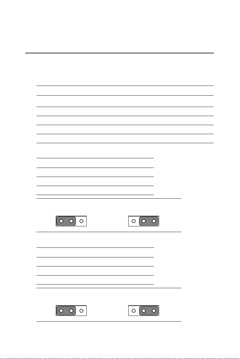
JP1: LCD Voltage Select
PIN FUNCTION
1-2 VCC3*
2-3 VCC
JP2: PC104+ VIO Select
PIN FUNCTION
1-2 VCC*
2-3 VCC3
123 123
123 123
Table of contents


