Actis VSBC-6862 User manual
Artisan Technology Group is your source for quality
new and certied-used/pre-owned equipment
• FAST SHIPPING AND
DELIVERY
• TENS OF THOUSANDS OF
IN-STOCK ITEMS
• EQUIPMENT DEMOS
• HUNDREDS OF
MANUFACTURERS
SUPPORTED
• LEASING/MONTHLY
RENTALS
• ITAR CERTIFIED
SECURE ASSET SOLUTIONS
SERVICE CENTER REPAIRS
Experienced engineers and technicians on staff
at our full-service, in-house repair center
WE BUY USED EQUIPMENT
Sell your excess, underutilized, and idle used equipment
We also offer credit for buy-backs and trade-ins
www.artisantg.com/WeBuyEquipment
REMOTE INSPECTION
Remotely inspect equipment before purchasing with
our interactive website at www.instraview.com
LOOKING FOR MORE INFORMATION?
Visit us on the web at www.artisantg.com for more
information on price quotations, drivers, technical
specications, manuals, and documentation
Contact us: (888) 88-SOURCE | sales@artisantg.com | www.artisantg.com
SM
View
Instra

USER'S GUIDE
VSBC-6862
VME Single Board Computer with
PowerQUICC II processor
Revision 1.43
3105
ACTIS Computer
www.actis-computer.com
Artisan Technology Group - Quality Instrumentation ... Guaranteed | (888) 88-SOURCE | www.artisantg.com

VSBC-6862 Rev 1.43
2
Artisan Technology Group - Quality Instrumentation ... Guaranteed | (888) 88-SOURCE | www.artisantg.com

Rev. 1.43
User's Guide
3
Table of contents
1
Product description _________________________________________________________ 7
1.1.
Introduction_____________________________________________________________ 7
1.2.
Features _______________________________________________________________ 8
1.3.
Photograph _____________________________________________________________ 9
1.4.
Block diagram__________________________________________________________ 10
1.5.
Component location _____________________________________________________ 11
2
Peripherals description _____________________________________________________ 13
2.1.
FLASH memory ________________________________________________________ 13
2.2.
SDRAM memory________________________________________________________ 13
2.3.
SRAM memory _________________________________________________________ 14
2.4.
Real Time Clock with SRAM memory________________________________________ 14
2.5.
IP modules ____________________________________________________________ 14
2.6.
Board registers _________________________________________________________ 15
2.7.
VME interface __________________________________________________________ 15
2.8.
I2C EEPROM __________________________________________________________ 17
2.9.
Fast Ethernet ports ______________________________________________________ 17
2.10.
SMC1 and SMC2 serial ports ______________________________________________ 17
2.11.
SCC multi-protocols serial ports ____________________________________________ 18
2.12.
I2C interface ___________________________________________________________ 19
2.13.
LED displays___________________________________________________________ 19
3
Connectors & jumpers______________________________________________________ 21
3.1.
Push Button: BP1 _______________________________________________________ 23
3.2.
Rotary switch: SW1______________________________________________________ 23
3.3.
IP module strobes, header J1______________________________________________ 24
3.4.
Jumper: J2 ____________________________________________________________ 25
3.5.
Jumper: J3 ____________________________________________________________ 26
3.6.
Jumpers: J4, J5, J6, J7___________________________________________________ 27
3.7.
Jumper: J8 ____________________________________________________________ 28
3.8.
Two RS-232 terminal ports, and I2C bus: P13, P4 ______________________________ 29
3.9.
Four multi-protocols serial ports P7,P8,P9, P10________________________________ 31
3.10.
Two Fast Ethernet ports, connectors P11, P12 ________________________________ 33
3.11.
IEEE-1149.1 interface, connector P3 ________________________________________ 34
3.12.
VME bus, P1 connector __________________________________________________ 35
3.13.
VME bus, P2 connector __________________________________________________ 36
3.14.
Four IP module logic interface, connectors P3A, P4A, P5A, P6A___________________ 38
3.15.
Four IP module I/O signals, connectors P3C, P4C, P5C, P6C_____________________ 39
3.16.
Real time clock battery, circuit U5___________________________________________ 40
3.17.
Fuses protection ________________________________________________________ 41
4
Software description _______________________________________________________ 43
4.1.
Introduction____________________________________________________________ 43
4.2.
FLASH memory ________________________________________________________ 44
4.2.1.
FLASH initialization____________________________________________________ 44
4.2.2.
FLASH Programming __________________________________________________ 45
4.2.3.
FLASH chip erase ____________________________________________________ 46
4.2.4.
FLASH sector erase ___________________________________________________ 46
Artisan Technology Group - Quality Instrumentation ... Guaranteed | (888) 88-SOURCE | www.artisantg.com

VSBC-6862 Rev 1.43
4
4.2.5.
FLASH sector protection: option on request_________________________________ 47
4.3.
SDRAM memory________________________________________________________ 48
4.3.1.
SDRAM initialization___________________________________________________ 48
4.4.
SRAM memory _________________________________________________________ 50
4.5.
Real Time Clock with SRAM memory________________________________________ 51
4.5.1.
RTC registers read operation ____________________________________________ 52
4.5.2.
RTC registers write operation____________________________________________ 52
4.6.
IP modules ____________________________________________________________ 54
4.6.1.
Memory spaces ______________________________________________________ 57
4.6.2.
Registers ___________________________________________________________ 57
4.6.3.
Interrupt functions_____________________________________________________ 58
4.6.4.
DMA functions _______________________________________________________ 59
4.7.
VME operations ________________________________________________________ 61
4.7.1.
Jumpers ____________________________________________________________ 61
4.7.2.
Registers ___________________________________________________________ 61
4.7.3.
VME master _________________________________________________________ 62
4.7.4.
VME slave __________________________________________________________ 64
4.7.5.
VME interrupter ______________________________________________________ 66
4.7.6.
VME interrupt handler__________________________________________________ 66
4.7.7.
VME Mailbox ________________________________________________________ 66
4.7.8.
VME system controller _________________________________________________ 67
4.7.9.
Specific features for VME_______________________________________________ 67
4.7.10.
General remarks for VME_____________________________________________ 67
4.8.
Serial I2C EEPROM _____________________________________________________ 68
4.9.
Fast Ethernet ports ______________________________________________________ 69
4.9.1.
Transceivers description________________________________________________ 69
4.9.2.
MPC-8260 I/O ports ___________________________________________________ 70
4.9.3.
Transceivers operations ________________________________________________ 71
4.10.
SMC1 and SMC2 serial ports ______________________________________________ 75
4.10.1.
MPC-8260 I/O ports _________________________________________________ 75
4.10.2.
ACTIS Console Cable _______________________________________________ 75
4.11.
SCC serial ports ________________________________________________________ 76
4.11.1.
RS-232 option _____________________________________________________ 76
4.11.2.
RS-422/RS-485/V.35 option___________________________________________ 77
4.11.3.
ACTIS Serial Cable _________________________________________________ 78
4.11.4.
MPC-8260 I/O ports _________________________________________________ 79
4.12.
I2C interface ___________________________________________________________ 80
4.13.
Auxiliary LEDs__________________________________________________________ 80
5
Summary of board resources ________________________________________________ 81
5.1.
Chip Select ____________________________________________________________ 81
5.2.
Local Board registers ____________________________________________________ 81
5.3.
Interrupt sources________________________________________________________ 82
5.4.
Reset sources__________________________________________________________ 82
5.5.
Power description _______________________________________________________ 84
5.6.
Power consumption _____________________________________________________ 84
5.7.
MPC-8260 I/O ports assignment____________________________________________ 85
6
Board initialization_________________________________________________________ 89
6.1.
Clock configuration ______________________________________________________ 89
6.2.
Reset Word____________________________________________________________ 90
6.3.
MPC-8260 internal registers_______________________________________________ 91
6.4.
MPC-8260 I/O ports _____________________________________________________ 93
6.5.
Chip select ____________________________________________________________ 96
6.6.
Serial EEPROM ________________________________________________________ 96
6.7.
Boot code _____________________________________________________________ 98
Artisan Technology Group - Quality Instrumentation ... Guaranteed | (888) 88-SOURCE | www.artisantg.com

Rev. 1.43
User's Guide
5
7
Registers definition ________________________________________________________ 99
8
Characteristics __________________________________________________________ 111
9
Physical board definition ___________________________________________________ 113
9.1.
PCB dimensions _______________________________________________________ 113
9.2.
Front panel ___________________________________________________________ 114
10
Software available ___________________________________________________ 115
10.1.
Debug tools___________________________________________________________ 115
10.2.
ECMON______________________________________________________________ 115
10.2.1.
Command description ______________________________________________ 116
10.2.2.
Advanced information_______________________________________________ 119
10.2.3.
Typical example ___________________________________________________ 120
10.3.
VxWorks _____________________________________________________________ 120
10.4.
Linux ________________________________________________________________ 120
10.5.
Other________________________________________________________________ 120
11
Hardware available___________________________________________________ 121
11.1.
List of ACTIS's IP modules _______________________________________________ 121
11.2.
List of ACTIS's 6U transition modules_______________________________________ 123
11.3.
List of ACTIS's 6U VME boards ___________________________________________ 123
12
Technical support____________________________________________________ 125
13
Ordering information__________________________________________________ 127
14
OEM Warranty ______________________________________________________ 129
15
Appendix___________________________________________________________ 131
15.1.
Application examples with the VSBC-6862___________________________________ 131
15.1.1.
Example A: Application with VME boards _______________________________ 131
15.1.2.
Example B: Application with non-VME boards____________________________ 132
15.1.3.
Example C: Application in stand-alone__________________________________ 133
16
Index______________________________________________________________ 135
Artisan Technology Group - Quality Instrumentation ... Guaranteed | (888) 88-SOURCE | www.artisantg.com

VSBC-6862 Rev 1.43
6
List of figures
Figure 1: Photograph............................................................................................................................... 9
Figure 2: Block diagram......................................................................................................................... 10
Figure 3: Component location ............................................................................................................... 11
Figure 4: Connectors and jumpers location........................................................................................... 22
Figure 5: Push button location............................................................................................................... 23
Figure 6: Rotary switch location ............................................................................................................ 23
Figure 7: Jumper J1 location................................................................................................................ 24
Figure 8: Jumper J2 location................................................................................................................. 25
Figure 9: Jumper J3 location................................................................................................................. 26
Figure 10: Communication ports jumpers in RS-232 mode.................................................................. 27
Figure 11: Communication ports jumpers example............................................................................... 27
Figure 12: Jumper J8 location............................................................................................................... 28
Figure 13: Connector P13 pinout .......................................................................................................... 29
Figure 14: Connector P4 pinout ............................................................................................................ 30
Figure 15: Communication ports pinout ................................................................................................ 31
Figure 16: Termination resistor networks example ............................................................................... 32
Figure 17: Fast Ethernet ports pinout.................................................................................................... 33
Figure 18: JTAG port pinout.................................................................................................................. 34
Figure 19: Real Time Clock battery....................................................................................................... 40
Figure 20: VME slave window............................................................................................................... 65
Figure 21: Reset scheme ...................................................................................................................... 83
Figure 22: PCB dimensions.................................................................................................................113
Figure 23: Front panel.........................................................................................................................114
Figure 24: Application example with VME boards............................................................................... 131
Figure 25: Application example with non-VME boards ....................................................................... 132
Figure 26: Application example in stand-alone ................................................................................... 133
For up to date documentation, please refer also to our web site at http://www.actis-computer.com .
While efforts have been made to ensure the accuracy of this document, and although the information contained in
this document is believed to be correct, ACTIS Computer S.A. can not be held responsible for any error or for any
resulting consequential losses. ACTIS Computer S.A may change or improve the specifications of its products at
any time without prior notification.
Total or partial reproduction of this document or any kinds is not allowed without the written authorization of
ACTIS Computer.
Licenses and trademarks
All licenses and trademarks are property of their respective owners.
This manual is copyrighted, all rights reserved. It may not be copied, photocopied, translated, or reduced to any
electronic medium or machine-readable form without ACTIS Computer prior permission.
© ACTIS Computer, 2000-2005
Artisan Technology Group - Quality Instrumentation ... Guaranteed | (888) 88-SOURCE | www.artisantg.com

Rev. 1.43
User's Guide
7
1
Product description
1.1. Introduction
Today industrial applications are growing in telecom market due to the demand of networked
architecture. This method offers great advantage where complex processes are handled and where
real time tasks are the critical features.
The VSBC-6862 combines the best possibilities with its flexible industrial interface and its wide range
of communications ports.
This single board computer is built around a communication-oriented processor: The PowerQUICC II
(MPC-8260) is a member of the PowerPC family of MOTOROLA semiconductors division. This
processor provides a very efficient architecture with two RISC processors built in the same chip: a
PowerPC core controls all host system operations, and a dedicated RISC processor for the
communication part.
The MPC-8260 integrates two main components, the embedded PowerPC core and the
Communications Processor Module (CPM). This dual-processor architecture is more efficient than
traditional architectures because the CPM offloads peripheral tasks from the embedded PowerPC
core.
This single board computer, in 6U form factor, is VME bus master and slave designed as a flexible
solution for communication applications. The VSBC-6862 is designed to offer a very open architecture
through two Fast Ethernet ports, four multi-protocol communication ports, and two RS-232 serial ports.
An other advantage is the flexible I/Os extension, which is implemented through the four VITA-4
standard IP Module slots supporting high performance 16-bit modules at up to 8 MHz clock with DMA
capabilities. These four slots offer to the user the possibility to customize its system very easily with
these cost saving modules.
The combination of the PowerPC core and the CPM dedicated RISC processor, along with the
versatility and performance of the MPC-8260 I/Os provides customers with an enormous potential in
developing networking and communications products while significantly reducing time-to-market
development stages.
Artisan Technology Group - Quality Instrumentation ... Guaranteed | (888) 88-SOURCE | www.artisantg.com

VSBC-6862 Rev 1.43
8
1.2. Features
This board has been designed to integrate the most required functions, including several Fast
Ethernet ports, communication ports, and the flexibility of four IP modules slots for easy user's
customization.
• Designed with Motorola PowerQUICC II processor
• A 32-bit EC603 ™ processor core rated at 280.0 MIPS at
200 MHz (Dhrystone 2.1)
• Dedicated 32-bit RISC processor for communication
protocol handling (CPM)
• Up to 128 MByte of SDRAM memory with burst
capabilities, 64 bit data bus width
• 8 or 16 MByte of Flash memory for non-volatile
information, divided on two bootables banks, one bank
dual-port with the VME bus
• 1 MByte of SRAM memory dual-port with the VME bus
Non-volatile operation through the VME stand-by signal
• A separate real time clock device with 32 kByte of battery
backed-up SRAM
Dual-port with the VME bus
• 8 kbit I2C EEPROM for board and user configuration
• Two Fast Ethernet 100Base-TX/10Base-T interfaces with
auto-negotiation capability
• Four HDLC serial ports selectable between RS-232 /
RS-422 / RS-485 or V.35
• Two RS-232 serial ports
• I2C bus for local extensions
• JTAG port for debug
• VME master, slave, system controller interface
• Four IP Modules slots, compatible with the
ANSI/VITA-4 1995 specification, support for 8 MHz
clock with DMA capabilities
Artisan Technology Group - Quality Instrumentation ... Guaranteed | (888) 88-SOURCE | www.artisantg.com

Rev. 1.43
User's Guide
9
1.3. Photograph
Figure 1: Photograph
The VMEbus Technology logo is a Trademark of the VMEbus International Trade Association.
Artisan Technology Group - Quality Instrumentation ... Guaranteed | (888) 88-SOURCE | www.artisantg.com
VSBC-6862 Rev 1.43
10
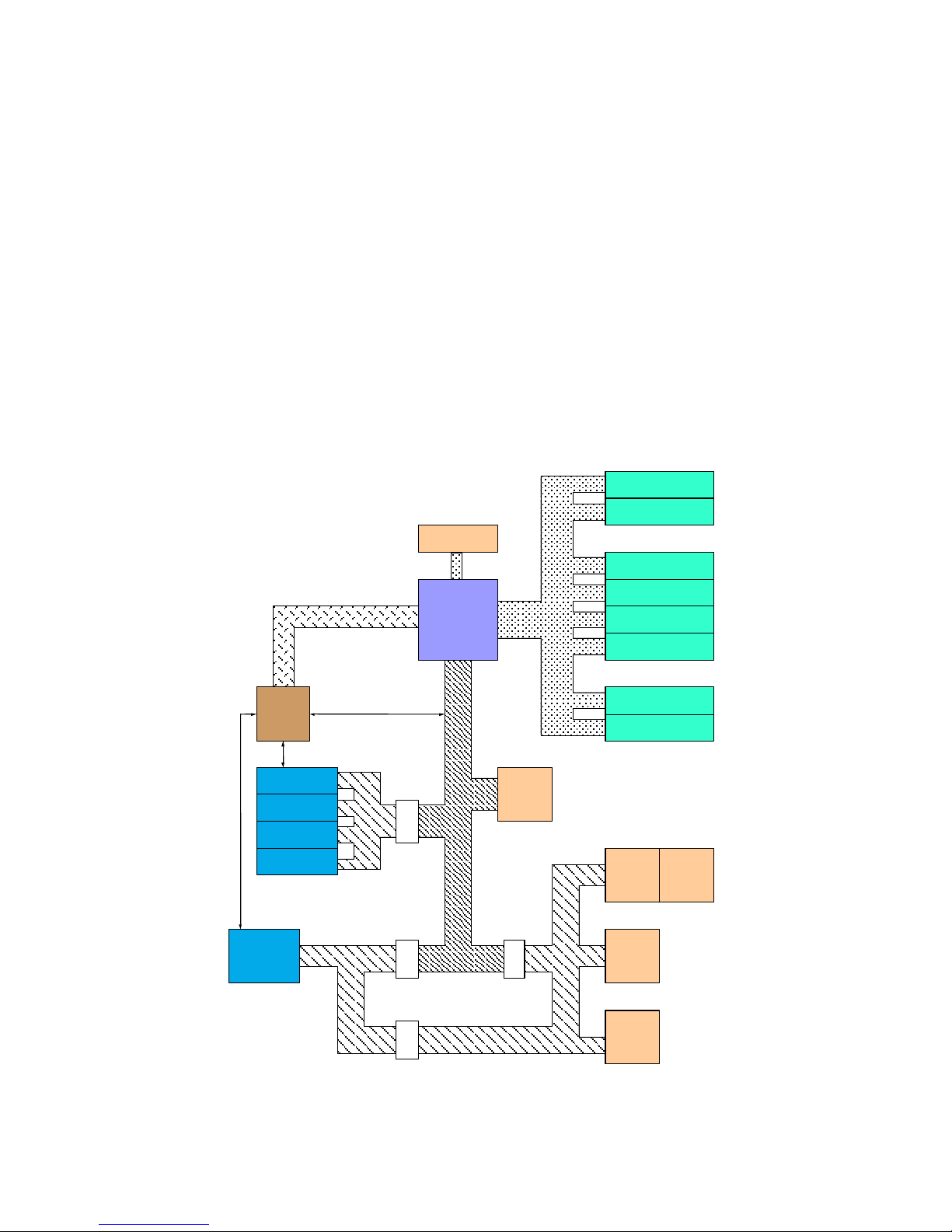
1.4. Block diagram
The VSBC-6862 architecture is divided in four main sections:
The CPU
This is the heart of the board, it is the MPC-8260 'PowerQUICC II' with a bus speed of 66MHz, CPM
speed of 133MHz and Core speed of 133 or 200MHz.
The memory section
This section includes the 128 MByte SDRAM on a 64-bit bus, the two 8 MByte Flash memory banks
on a 32-bit bus, the 1 MByte SRAM memory, and the battery backed-up RTC with SRAM.
The internal logic section including the IP carrier and the VME interface
This section handles all internal board logic like board registers, plus the handling of IP modules and
VME functions.
The I/O section
This section is the external part of the PowerQUICC II I/O ports; it contains the two RS-232 ports, the
four serial ports, and the two Fast Ethernet ports.
VME interface
IP slot A
IP slot B
IP slot C
IP slot D
SDRAM
128MB
Flash
8MB
Bank 0
Flash
8MB
Bank1
SRAM
1MB
VME backed-up
RTC
32kB SRAM
Battery backed-up
RS-232 A
RS-232 B
Serial Multiprotocol A
Serial Multiprotocol D
Serial Multiprotocol C
Serial Multiprotocol B
Fast Ethernet A
Fast Ethernet B
I2C EEPROM
MPC-8260
PLD
Figure 2: Block diagram
Artisan Technology Group - Quality Instrumentation ... Guaranteed | (888) 88-SOURCE | www.artisantg.com

Rev. 1.43
User's Guide
11
1.5. Component location
Figure 3: Component location
Artisan Technology Group - Quality Instrumentation ... Guaranteed | (888) 88-SOURCE | www.artisantg.com

VSBC-6862 Rev 1.43
12
Please note that on the VSBC-6862, some locations are not populated.
This was done either to avoid problems of component availability, either for debug purposes.
From the user side, its totally transparent, nothing has to be modified.
For special uses that need a precise component implementation, please contact ACTIS.
Artisan Technology Group - Quality Instrumentation ... Guaranteed | (888) 88-SOURCE | www.artisantg.com

Rev. 1.43
User's Guide
13
2
Peripherals description
The VSBC-6862 offers a wide choice of on-board peripheral or bus interface, which makes this board
very versatile. Most of these peripherals comes either directly from the processor interface, like the
serial ports, or from other interface unit, like the real time clock calendar.
The following sections will describe these peripheral features.
2.1. FLASH memory
Two banks of 4 or 8 MBytes Flash memory devices are available, for a total of 8 or 16 MBytes Flash.
Each Flash bank is formed by a group of two 16-bit devices, which provide a resulting 32-bit bus
interface for efficient instruction program storage.
Each bank is controlled by the Chip Select 0 (CS0) or Chip Select 2 (CS2) signal.
The Flash memory bank connected to the Chip Select 0 is the boot device. This bank must contain
both ResetWord used by the PowerQUICC II configuration and the boot code.
The VSBC-6862 provides a 'Bootbank' jumper to provide the ability to invert the CS0 and CS2 signals,
thus inverting the bootable Flash memory bank.
One Flash memory bank is also shared with the VME bus. This permits an external master to
reprogram the VSBC-6862 Firmware or use this memory as non-volatile device.
This device is command set compatible with JEDEC standard E2PROMs.
Commands are written to the command register using standard microprocessor write timings. Register
contents serve as input to an internal state-machine, which controls the erase and programming
circuitry.
2.2. SDRAM memory
This memory is handled by the powerful SDRAM timing machine contained in the MPC-8260.
The Chip Select 1 is used to control this memory.
The SDRAM machine provides an interface to synchronous DRAMs, using SDRAM pipelining, bank
interleaving, and back-to-back page mode to achieve the highest performance. This controller
supports directly all the SDRAM possibilities, like pipelining and interleaving.
The VSBC-6862 is supplied with 128 MBytes SDRAM on-board, organized with four 16 Mbitsx16
devices.
The 64 bits wide data bus is directly connected on the 60x bus of the MPC-8260 to achieve the best
performance.
Artisan Technology Group - Quality Instrumentation ... Guaranteed | (888) 88-SOURCE | www.artisantg.com

VSBC-6862 Rev 1.43
14
2.3. SRAM memory
1 MBytes of SRAM memory are provided on-board, this memory is controlled with the Chip Select 9.
This memory is shared between the PowerQUICC II and the VME bus.
It is organized in memory width of 32 bits.
A special function is provided for memory saving with the usage of the Stand-By power signal from the
VME bus. When the Board Power is shutdown, the SRAM memory will switch its power lines to the
VME Stand-By power signal.
2.4. Real Time Clock with SRAM memory
The VSBC-6862 includes a real time clock device, with as an additional feature, a battery backed 32
kbyte SRAM. This device is controlled by the Chip Select 3.
Its 32 kbyte SRAM provides flexible user data storage with retention capability by its SNAPHAT
battery pack. This device is connected on an 8 bits wide data path.
This device provides also functions like Alarm, Battery Test, and Watchdog function.
The RTC data are accessible like SRAM Bytes.
This device is also accessible from the VME bus.
Note: The SNAPHAT housing plugged on the M48T37V contains both battery and crystal.
Thus, for the minimum frequency error, the user has to calibrate the RTC in case of
battery replacement.
2.5. IP modules
The VSBC-6862 provides four IP module slots, which are compliant with the ANSI/VITA 4-1995.
It provides support for 8 MHz type as well as DMA modules.
The IP interface offers an architecture for I/O extension through inexpensive mezzanine modules for
various categories like:
• Digital and analog functions
• Serial communication controllers
• Network and fieldbus interfaces
This interface gives the possibility to easily customize the VSBC-6862.
This IP bus interface is implemented on the VSBC-6862 through a specific CPLD, which provides the
interface between the PowerQUICC II processor and the four IP module slots.
For overall information, please consult the Appendix: List of main ACTIS IP modules.
A choice of IP modules and transition modules from ACTIS Computer is
available on our web site:
www.actis-computer.com
Artisan Technology Group - Quality Instrumentation ... Guaranteed | (888) 88-SOURCE | www.artisantg.com

Rev. 1.43
User's Guide
15
The IP interface uses two processor chip selects to address all IP module spaces.
The Chip Select 4 is used to control the IP I/O, ID, and INT spaces.
The Chip Select 5 is used to control the IP memory spaces.
Each IP slot has is own set of registers to have the four IP slots fully independent.
The VSBC-6862 supports the two IRQ available on the IP modules.
Each IP slot has an own IRQ level attributed to the MPC-8260. If the both IRQ are active at the same
time on an IP module, the VSBC-6862 handles the IP IRQ 0 first, and then IP IRQ 1.
The IP DMA channels are controlled by the IDMA channels, with IP Slot A controlled by IDMA1, Slot B
controlled by IDMA2, Slot C controlled by IDMA3 and Slot D controlled by IDMA4
2.6. Board registers
The VSBC-6862 contains several registers for board features.
These registers are mapped in the same Chip Select 4 than the IP ID and I/O spaces.
These features can be divided in three functions:
• General board functions
Two registers are used to generate Reset on the board and to read the rotary
switch value.
• IP functions
Each of the four IP slot owns his set of registers to define and use IP modules.
• VME functions
Each VME window owns his set of registers to define and use
the VME bus.
2.7. VME interface
There is a VME master, slave, interrupter, interrupt-handler and system controller modules.
Each module can be considered as an independent module.
Some functions are controlled by jumpers for the VME module, as for Slot1function or Reset
utilization.
The VME master A32/A24/A16/D32/D16/D8
Two windows are available to access the VME bus.
They are controlled by the chip selects CS6 and CS7.
The release modes are selectable between ROR and RWD modes.
The VME slave A24/A16/D32/D16/D8
Two windows are available from VME bus:
An A16 window to access VME registers, including mailbox
An A24 window to access the VSBC-6862 memory spaces.
Artisan Technology Group - Quality Instrumentation ... Guaranteed | (888) 88-SOURCE | www.artisantg.com

VSBC-6862 Rev 1.43
16
The VME interrupter I(1-7)
The interrupter is able to generate any VME IRQ level and send a user-defined vector.
The VME interrupt-handler IH(1-7)
This interrupt-handler is able to recognize all IRQ VME levels.
All levels can be masked with the VHM register.
When an IRQ is coming from the VME side, an IRQ1 is sent to the MPC-8260.
The user can then read the IRQ levels active in the VHIL register.
Depending of the IRQ level to be acknowledged, the user can read the vector in the corresponding
offset in the VHV register.
When reading the vector, the interrupt acknowledge cycle is initiated.
The VME system controller.
This function can be enabled or disabled with the Slot1 jumper.
When the system controller is enabled, the VSBC-6862 provides the following functions:
- VME arbiter: SGL, PRI, or RRS depending of the VAM register.
- VME bus monitor: BTO(30)
- IACK daisy-chain driver.
- 16 MHz system clock generator.
Artisan Technology Group - Quality Instrumentation ... Guaranteed | (888) 88-SOURCE | www.artisantg.com

Rev. 1.43
User's Guide
17
2.8. I
2
C EEPROM
8 kbits of non-volatile memory is provided on the I2C bus.
This memory is used for board internal configuration (for example to store physical Fast Ethernet
addresses) and can also be used for user purposes.
2.9. Fast Ethernet ports
The two Fast Ethernet interfaces come directly from the MPC-8260 processor.
The physical layer is achieved with on-board fast Ethernet transceivers from SMSC: the LAN83C183.
The SMSC-LAN83C183 provides all of the IEEE 802.3u 100Base-TX and ISO802.3 10Base-T
Physical Layer (PHY) functions needed for workstations, bridge, router, and switch applications. It can
operate as a 100Mbps only device, or as a dual speed 10/100Mbps device with built-in auto-
negotiation possibility for speed selection. The SMSC-LAN83C183 supports the standard Media
Independent Interface (MII) for glueless interface with 10/100 Ethernet Media Access Controllers
(MAC).
The built-in IEEE 802.3u Auto-Negotiation feature automatically selects internal 10Base-T or
100Base-TX, full or half-duplex, as a result of negotiation between the station and its link partner.
The SMSC-LAN83C183 supports half and full-duplex operation at both 10Mbps and 100Mbps speeds.
It complies with ANSI X3T9 TP-PMD and includes MLT-3 Encoder/Decoder and Stream Cipher
scrambler/ de-scrambler functions for 100Base-TX.The SMSC-LAN83C183 supports Category 5
Unshielded Twisted Pair and Type 1 Shielded Twisted Pair wiring. The on-chip Serial Management
Interface features the Basic and Extended registers set. The 4B/5B Encoder and Decoder are also
included.
An on-board transformer provides a direct connection for a 10Base-T and 100Base-TX interface
2.10.SMC1 and SMC2 serial ports
The VSBC-6862 offers two RS-232 serial ports.
One of these general-purpose serial ports is available on the front panel RJ-45 connector, the other
one is available on an internal connector.
These serial ports can be typically used as system console ports.
Note that this type of port has no hardware flow control capability.
Artisan Technology Group - Quality Instrumentation ... Guaranteed | (888) 88-SOURCE | www.artisantg.com

VSBC-6862 Rev 1.43
18
2.11.SCC multi-protocols serial ports
The VSBC-6862 offers four independent serial ports.
In synchronous mode, all four ports have independents RX clock signals, but only SCC1 and SCC2
have TX Clocks signals.
These ports are directly controlled by the Serial Communication Controllers (SCC) included in the
PowerQUICC II. These SCC includes functions like support of many protocols like UART and HDLC, it
contains also FIFO buffers: 32 byte deep, and many more powerful options.
All the four ports are available on four Sub-D-HD-15 connectors on front panel.
The interface level of these ports can be RS-232/RS-422/RS-485 or V.35.
Switching between these options can be done through the 'serial mode' jumpers.
The serial ports 1 and 2 have an added function: they can be internally used to synchronize the
internal Baud Rate Generators (BRG) with external clock signals.
Note that due to pin multiplexing in the PowerQUICC II, the Transmit Clock for the serial port 4 can't
be used in same time with the IP slot B DMA channel. The user must use either DMA on IP B, either
Transmit Clock on serial port 4.
RS-232 mode
These VSBC-6862 ports are in a standard RS-232 mode.
The following signals are controlled by the PowerQUICC II:
TxD, RxD, TxC, RxC, CTS, RTS, and DCD
All ports support hardware handshaking and synchronous functions.
DSR signals are pulled-up to VCC to indicate that the board is powered-up.
RS-422/RS-485/V.35 modes
These VSBC-6862 ports are compatible with these three modes.
The following signals are controlled by the PowerQUICC II:
TxD, RxD, TxC, RxC in differential mode for RS-422, RS-485 and V.35
CTS, RTS and DCD in RS-232 mode for V.35
Note: As described above, the VSBC-6862 did not provides all defined signals for V.35, it provides
all 'transmission signals' but not for example, the loopback or ring indicator signals.
All ports support full and half-duplex mode, and supports also synchronous operations.
The internal I/O ports dedicated to RTS is connected to the internal data transmit enable signal.
This permits to determine the function for half or full-duplex modes as:
Full-duplex: configure RTS always active
Half-duplex: configure RTS as normal RTS
The PowerQUICC II has also the possibility to disable his receiver while emitting (see bit DRT in
register PSMR).
Each port has its own network resistors.
These resistors are on sockets. ACTIS choose to implement manual network resistors to keep the RS-
485 network always working, independently of the power state of the VSBC-6862.
These resistors network are to be installed only when the corresponding serial port is at one of both
ends of the RS-485 network cable.
Artisan Technology Group - Quality Instrumentation ... Guaranteed | (888) 88-SOURCE | www.artisantg.com
Rev. 1.43
User's Guide
19
2.12.I
2
C interface
The VSBC-6862 provides an I2C interface bus for on-board serial EEPROM accesses and user
purposes.
The board provides external accesses to this bus through an internal connector.
2.13.LED displays
The VSBC-6862 allows monitoring for a wide range of board activities, these status are available for
user check on the front panel.
The Power and Access LEDs functions are hardware fixed.
The Fast Ethernet LEDs can be reconfigured by setting the corresponding parameters in the
transceivers. The configuration of these LEDs is described in the Fast Ethernet transceiver
description.
The two Auxiliary LEDs are user defined with PowerQUICC II I/O ports. They are intended to provide
the user a flexible meaning to signal states on the front panel. These indicators have to be handled by
the user.
These two LEDs are active low.
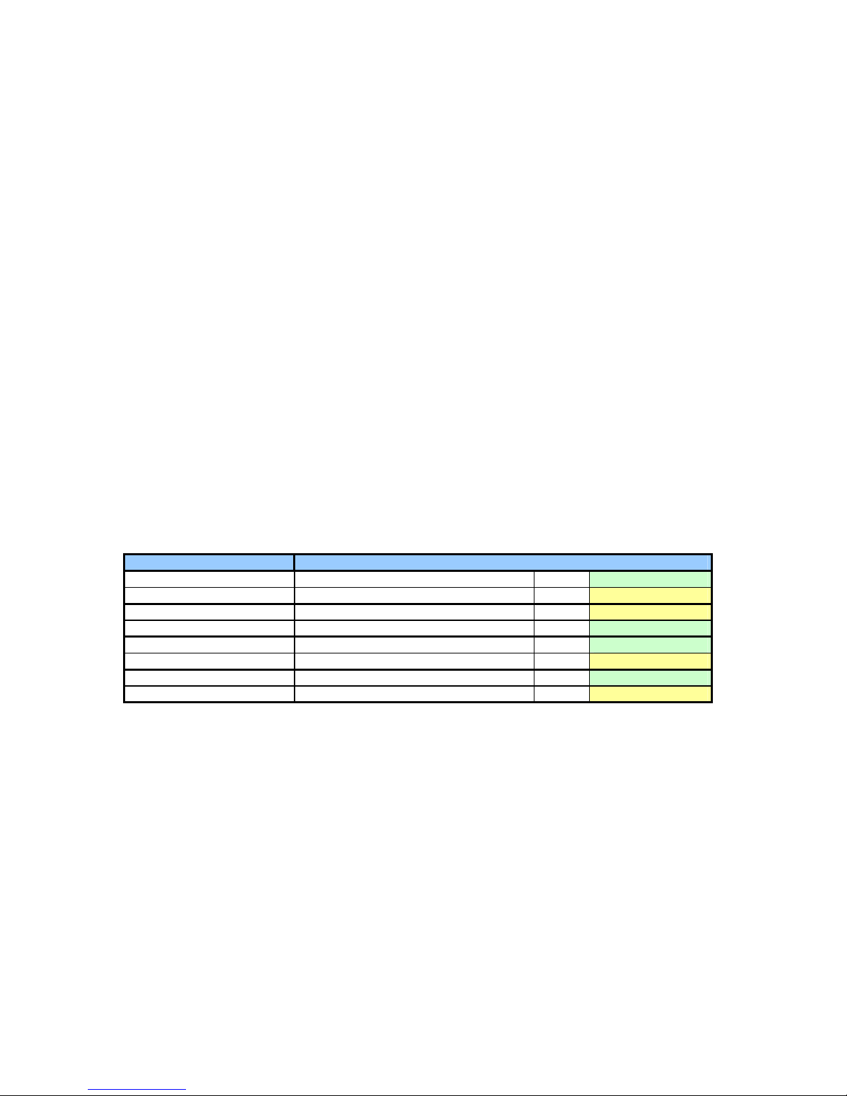
The following table provides the relation between the front panel LED's and their corresponding
condition sources.
LED reference Source Ref Color
Power OK 5V power ok and 5V IP ok D1 Green
Access Internal logic (SDRAM, Reset, Slave) D5 Yellow
Auxiliary 0 MPC-8260 I/O port C24 P13 Yellow
Auxiliary 1 MPC-8260 I/O port C30 P13 Green
Fast Ethernet 1 Link SMSC-83C183 1, signal LED3 P12 Green
Fast Ethernet 1 Activity SMSC-83C183 1, signal LED2 P12 Yellow
Fast Ethernet 2 Link SMSC-83C183 2, signal LED3 P11 Green
Fast Ethernet 2 Activity SMSC-83C183 2, signal LED2 P11 Yellow
The 'Power' Led blinking can typically indicate a problem on an IP module. This LED indicates the
power state after the protecting fuses.
The 'Access' Led indicates:
- the Reset state
- an local access to SDRAM
- an slave access to the board
Artisan Technology Group - Quality Instrumentation ... Guaranteed | (888) 88-SOURCE | www.artisantg.com
Table of contents


