1
SNVU578A–October 2017–Revised March 2018
Submit Documentation Feedback Copyright © 2017–2018, Texas Instruments Incorporated
User's Guide for the LMZM23601 and LMZM23600 Evaluation Boards
User's Guide
SNVU578A–October 2017–Revised March 2018
User's Guide for the LMZM23601 and LMZM23600
Evaluation Boards
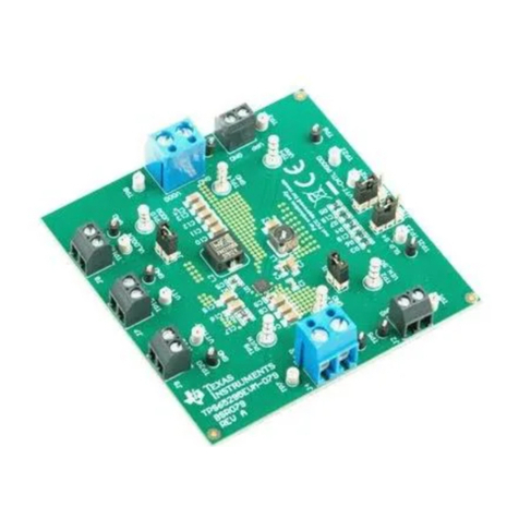
The evaluation modules (EVM) for the LMZM23601 and LMZM23600 are designed as easy-to-use
platforms to help evaluate the features and performance of these DC/DC step-down power modules. This
guide provides an overview of the board settings and board layout along with connection diagrams and
several performance curves for each device in the family.
Contents
1 Description.................................................................................................................... 3
2 Getting Started............................................................................................................... 4
3 Schematic..................................................................................................................... 6
3.1 Adjustable Output Voltage Versions.............................................................................. 6
3.2 Fixed Output Voltage Versions.................................................................................... 7
4 Bill of Materials............................................................................................................... 8
4.1 Adjustable Output Voltage Versions.............................................................................. 8
4.2 Fixed Output Voltage Versions.................................................................................... 9
5 Performance Data.......................................................................................................... 10
5.1 VOUT = 15 V......................................................................................................... 10
5.2 VOUT = 12 V......................................................................................................... 11
5.3 VOUT = 5 V........................................................................................................... 12
5.4 VOUT = 3.3 V ........................................................................................................ 13
5.5 VOUT = 2.5 V ........................................................................................................ 14
6 PCB Layout ................................................................................................................. 15
6.1 Adjustable Output Voltage Versions............................................................................ 15
6.2 Fixed Output Voltage Versions.................................................................................. 19
List of Figures
1 EVM User Interface for the Adjustable Output Voltage Options....................................................... 4
2 EVM User Interface for the Fixed (5-V and 3.3-V) Output Voltage Options ......................................... 4
3 Jumper Configuration Details for Each Board ........................................................................... 5
4 Schematic for the Adjustable Output Voltage Versions of the Module ............................................... 6
5 Schematic for the Fixed Output Voltage Versions of the Module ..................................................... 7
6 Bill Of Materials for the Adjustable Output Voltage Versions of the Module......................................... 8
7 Bill Of Materials for the Fixed Output Voltage Versions of the Module............................................... 9
8 Efficiency for VOUT = 15 V.................................................................................................. 10
9 Load Transient Response for VOUT = 15 V 10% to 100% Load Step, FPWM ...................................... 10
10 Output Ripple for VOUT = 15 V, 20 MHz BW............................................................................. 10
11 Output Ripple for VOUT = 15 V, 250 MHz BW........................................................................... 10
12 Efficiency for VOUT = 12 V ................................................................................................. 11
13 Load Transient Response for VOUT = 12 V 10% to 100% Load Step, FPWM ...................................... 11
14 Output Ripple for VOUT = 12 V, 20 MHz BW............................................................................. 11
15 Output Ripple for VOUT = 12 V, 250 MHz BW........................................................................... 11
16 Efficiency for VOUT = 5 V .................................................................................................. 12
17 Load Transient Response for VOUT = 5 V 10% to 100% Load Step, FPWM........................................ 12
