Embedded ARTiGO-A1150 User manual

user manual
ARTiGO-A1150
Barebone System with
EPIA-P900 Embedded Board
Revision
1.0
3
102
-
06252012
-
1125
II
Tested To Comply
With FCC Standards
FOR HOME OR OFFICE USE
Copyright
Copyright © 2013 VIA Technologies Incorporated. All rights reserved.
No part of this docu ent ay be reproduced, trans itted, transcribed, stored in a retrieval syste , or
translated into any language, in any for or by any eans, electronic, echanical, agnetic, optical,
che ical, anual or otherwise without the prior written per ission of VIA Technologies, Incorporated.
Trademarks
All trade arks are the property of their respective holders.
Disclaimer
No license is granted, i plied or otherwise, under any patent or patent rights of VIA Technologies. VIA
Technologies akes no warranties, i plied or otherwise, in regard to this docu ent and to the products
described in this docu ent. The infor ation provided in this docu ent is believed to be accurate and
reliable as of the publication date of this docu ent. However, VIA Technologies assu es no responsibility
for the use or isuse of the infor ation (including use or connection of extra device/equip ent/add-on
card) in this docu ent and for any patent infringe ents that ay arise fro the use of this docu ent. The
infor ation and product specifications within this docu ent are subject to change at any ti e, without
notice and without obligation to notify any person of such change.
VIA Technologies, Inc. reserves the right the ake changes to the products described in this anual at any
ti e without prior notice.
Regulatory Compliance
FCC
FCCFCC
FCC-
--
-A Radio Frequency Interference
A Radio Frequency InterferenceA Radio Frequency Interference
A Radio Frequency Interference Statement
Statement Statement
Statement
This equip ent has been tested and found to co ply with the li its for a class A digital device, pursuant to
part 15 of the FCC rules. These li its are designed to provide reasonable protection against har ful
interference when the equip ent is operated in a co ercial environ ent. This equip ent generates, uses,
and can radiate radio frequency energy and, if not installed and used in accordance with the instruction
anual, ay cause har ful interference to radio co unications. Operation of this equip ent in a
residential area is likely to cause har ful interference, in which case the user will be required to correct the
interference at his personal expense.
Notice 1
Notice 1Notice 1
Notice 1
The changes or odifications not expressly approved by the party responsible for co pliance could void
the user's authority to operate the equip ent.
Notice 2
Notice 2Notice 2
Notice 2
Shielded interface cables and A.C. power cord, if any, ust be used in order to co ply with the e ission
li its.
Notice 3
Notice 3Notice 3
Notice 3
The product described in this docu ent is designed for general use, VIA Technologies assu es no
responsibility for the conflicts or da ages arising fro inco patibility of the product. Check co patibility
issue with your local sales representatives before placing an order.

III
Battery Recycling and Disposal
Only use the appropriate battery specified for this product.
Do not re-use, recharge, or reheat an old battery.
Do not attempt to force open the battery.
Do not discard used batteries with regular trash.
Discard used batteries according to local regulations.
Safety Precautions
Always read the safety instructions carefully.
eep this User's Manual for future reference.
All cautions and warnings on the equipment should be noted.
eep this equipment away from humidity.
Lay this equipment on a reliable flat surface before setting it up.
Make sure the voltage of the power source and adjust properly 110/220V
before connecting the equipment to the power inlet.
Place the power cord in such a way that people cannot step on it.
Always unplug the power cord before inserting any add-on card or module.
If any of the following situations arises, get the equipment checked by
authorized service personnel:
•The power cord or plug is damaged.
•Liquid has penetrated into the equipment.
•The equipment has been exposed to moisture.
•The equipment has not worked well or you cannot get it work according
to User's Manual.
•The equipment has dropped and damaged.
•The equipment has obvious sign of breakage.
Do not leave this equipment in an environment unconditioned or in a
storage temperature above 60°C (140°F). The equipment may be damaged.
Do not leave this equipment in direct sunlight.
Never pour any liquid into the opening. Liquid can cause damage or
electrical shock.
Do not place anything over the power cord.
Do not cover the ventilation holes. The openings on the enclosure protect
the equipment from overheating

IV
Box Contents
1 x ARTiGO-A1150 system
1 x AC-to-DC adapter, DC 12V/5A, 60W
1 x Power cable, 180 cm, USA type
1 x Installation Guide

V
Ordering Information
Model Number Description
ATG-1150-1D10A1 VIA Eden™ X2 1.0GHz Processor based
Embedded Sys em, wi h 1 x VGA, 1 x
HDMI
®
, HD Audio (Line-in, Line-ou and
Mic-in), 1 x GigaLAN, 4 x USB 2.0 1 x USB
device, DC-In 12V
Optional Accessories
Power Cord
99G33-02034C Power cord wi h PSE mark, 180 cm
for Japan marke
99G33-02033C Power cord, 180 cm, Europe ype
99G33-02031C Power cord, 180 cm, UK ype
SD Card Reader
EMIO-5130-00A1 1 x slo SD card reader
WLAN Module
EMIO-1533-00A1 802.11 b/g/n Wireless LAN USB Module
EMIO-1530-80A1 802.11 b/g Wireless LAN USB Module for
USA
EMIO-1530-90A1 802.11 b/g Wireless LAN USB Module for
Europe

VI
T
ABLE OF
C
ONTENTS
1 Product Overview............................................................................................... 1
Key Features........................................................................................................... 2
Specifications ......................................................................................................... 4
ARTiGO-A11 0 Dimensions........................................................................... 7
2 Front, Rear and Side I/O Pin Descriptions and Functionality........ 9
Front I/O Layout ................................................................................................10
Rear I/O Layout ..................................................................................................10
Side I/O Layout...................................................................................................10
I/O Pin Description ...........................................................................................11
Power Button.................................................................................................11
LED Indicators (Power LED and HDD LED)...................................11
USB device port.............................................................................................11
USB 2.0 ports..................................................................................................11
Audio Ports (Line-out, Line-in and Mic-in)........................................12
VGA Port ..........................................................................................................12
HDMI
®
Port......................................................................................................13
LAN Port ...........................................................................................................13
Power Input (DC-In) Port..........................................................................13
3 Basic installation .................................................................................................1
Installing the memory .....................................................................................16
Opening the Top Cover Chassis................................................................18
Installing the SATA 2. ” Hard Disk ............................................................19
Installing the SD Card Reader .....................................................................23
Installing the WLAN kit ...................................................................................27
Installing VESA Mount Bracket ...................................................................31
4 BIOS Setup............................................................................................................33
Entering the BIOS Setup Menu ..................................................................34
Control Keys .........................................................................................................34
Getting Help ........................................................................................................3
System Overview ...............................................................................................36
AMIBIOS............................................................................................................36
Processor ..........................................................................................................36
System Memory.............................................................................................36
System Time ....................................................................................................36
System Date ....................................................................................................37
Advanced Settings ............................................................................................38
CPU Configuration ...........................................................................................39

VII
Nano CPU TM3 Function ........................................................................39
SATA Configuration .........................................................................................40
Hard Disk Information................................................................................40
SuperIO Configuration ...................................................................................42
Serial Ports 1 to 2 Address........................................................................42
Hardware Health Configuration ...............................................................43
Smart FAN 1 ...................................................................................................43
ACPI Configuration...........................................................................................44
Suspend Mode ..............................................................................................44
ACPI Version Features ...............................................................................44
APM Configuration...........................................................................................4
Power Button Mode...................................................................................4
Restore on AC/Power Loss......................................................................46
Resume on LAN............................................................................................46
Resume on RTC Alarm...............................................................................46
RTC Alarm Date (Days)..............................................................................47
System Time ....................................................................................................47
Spread Spectrum Configuration ................................................................48
CPU Spread Spectrum Setting ...............................................................48
USB Configuration ............................................................................................49
USB Device Mode Enable........................................................................49
USB Endpoint0 Ctrl Clk..............................................................................49
USBD Interface Selection..........................................................................49
CRB Configuration ............................................................................................ 0
DRAM Clock.................................................................................................... 0
Select Display Device 1 and 2................................................................ 0
VGA Share Memory (Frame Buffer) ................................................... 1
OnChip HDAC Device............................................................................... 1
WATCH-DOG ................................................................................................ 1
VT6130 LAN Control.................................................................................. 1
LAN Option ROM......................................................................................... 1
Boot Settings........................................................................................................ 2
Boot Settings Configuration.................................................................... 2
Quick Boot....................................................................................................... 3
Quiet Boot ....................................................................................................... 3
Bootup Num-Lock ....................................................................................... 3
Wait for ‘F1’ if Error ..................................................................................... 3
Hit ‘DEL’ Message Display........................................................................ 3
Boot Device Priority .......................................................................................... 4
1
st
Boot Device .............................................................................................. 4
Security Settings..................................................................................................
Change Supervisor Password ................................................................
Change User Password ............................................................................
Clear User Password...................................................................................

VIII
Password Check............................................................................................ 6
Exit Options .......................................................................................................... 7
Save Changes and Exit.............................................................................. 7
Discard Changes and Exit........................................................................ 7
Discard Changes .......................................................................................... 7
Load Optimal Defaults............................................................................... 7
Driver Installation............................................................................................... 9
Microsoft Driver Support................................................................................60
Linux Driver Support ........................................................................................60

1
1
Product Overview

2
The ARTiGO-A11 0 is an ultra compact embedded system. Its
based on the VIA EPIA-P900 Pico-ITX form factor board and
powered by high performance VIA Eden X2 1.0 GHz processor.
The ARTiGO-A11 0 chassis is designed with dual-sided I/O access
plates for easy integration.
The mechanical parts in the ARTiGO-A11 0 consist of a system
chassis, removable top cover and front faceplate. The ARTiGO-
A11 0 comes with built-in SATA data and power cables for 2. ”
SATA hard disks. The ARTiGO-A11 0 is also available with an
optional SD card reader and WLAN (wireless LAN) module.
KEY FEATURES
Ultra compact chassis for the EPIA-P900
The ARTiGO-A11 0 houses the VIA EPIA-P900 Pico-ITX form factor
board with a maximum height of 6 mm, width of 99 mm and
length of 146 mm. The ARTiGO-A11 0 chassis is rugged
aluminum case, design to ensure maximum reliability.
Small and stylish design
The ARTiGO-A11 0 housing is composed of three mechanical
parts: the chassis, removable top cover and front faceplate. Its
space saving design enables it to be installed in space critical
environments.
Optimized integration with front and rear I/O access
Front and rear I/O access enables the ARTiGO-A11 0 to easily
supports various applications as well as for easy integration and
quick setup.
uick Data Transmission by USB device port
The ARTiGO-A11 0 comes with one USB device port that allows
ARTiGO-A11 0 as a USB Client device for user friendly and quick
data transfer to another computer.
Display Acceleration
The ARTiGO-A11 0 supports hardware acceleration of MPEG-2,
WMV9 and H.264 for 1080p full HD display
Shock Resistant
The ARTiGO-A11 0 is shock resistant to 20G for maximum
reliability.

3
Networking support
The ARTiGO-A11 0 is equipped with an RJ-4 port that supports
Gigabit Ethernet. The ARTiGO-A11 0 also has a WLAN module
option that gives the ARTiGO-A11 0 freedom of WiFi access.
Embedded OS ready
The ARTiGO-A11 0 is 100% compatible with several operating
systems including Microsoft Widows XP, Windows XP Embedded,
and Linux. ARTiGO-A11 0 is also well suited to the newest
Microsoft operating system which is the Windows 7.

4
SPECIFICATIONS
Processor Core
Logic System
CPU
• VIA Eden X2 1.0 GHz processor
• NanoBGA2 package
• 800 MHz Front ide Bus speed
• 2 MB L2 Cache memory
System Chipset
• VIA VX900 Unified Digital Media IGP chipset
BIOS
• AMI BIO
• 8Mbit LPC Flash Memory
System Power Management
• Times Power On
• ACPI upported
System Memory Technology
• One DDR3 1066 MHz DRAM ODIMM slot
Maximum Capacity
• upports memory sizes up to 4 GB
Graphic Controller
• Integrated VIA Chrome™ 9 HCM DX9 3D/2D Graphics
and Video Processor
• Integrated Unified Video Decoding Accelerator for
MPEG-2(VLD), WMV9/VC1(VLD or iDCT), H.264(VLD)
Display Memory
• Optimized hared Memory Architecture (UMA), supports
up to 512 MB frame buffer using system memory
CRT Interface
• upports one VGA connector
• Pixel resolution support up 1920 x 1200
DMI
®
Interface
• upports one HDMI
®
port
Dual Independent Display
• Two independent display engines built-in VX900 chipset,
upport CRT+HDMI at different resolutions, pixel depths,
and refresh rates with completely two different video
contents supports
Gigabit Ethernet
Controller
• Onboard VIA VT6130G Gigabit Ethernet controllers
Interface
• One RJ-45 connector
• upports Wake On LAN (WOL)
Audio Controller
• VIA VT2021 High Definition Audio Codec
Interface
• upport three 3.5Ø Audio jacks (Line-in, Line-out, and Mic-in)

5
USB 2.0 USB 2.0 ports
• upports four U B 2.0 ports
• upports one U B device port
Storage
nterface
ard Disk Drive
• One 2.5-inch hard disk drive bay supports 2.5-inch ATA
interface HDD and Flash D
SD
• Reserve space for optional support of one D card by
EMIO-5130 (optional) D card reader
System ndicator
Power Status LED
• One green color LED
DD Activity LED
• One red color LED
Watchdog Timer
Output
• ystem reset
Interval
• Programmable 1~255 sec.
/O connectors Front I/O
• Two U B 2.0 host ports
• One U B device port
• Three 3.5Ø Audio jacks support
• Line-in, Line-out and Mic.-in
Rear I/O
• One VGA connector (D- ub 15-pin female connector)
• Two U B 2.0 host ports
• One HDMI
®
connector
• One RJ-45 connector for Gigabit Ethernet connection
Left I/O
• One D slot for D card (optional)
Power Supply Power Consumption
• Typical 12.84W, Maximum 20.72W
Input Voltage
• DC 12V Power Input
• Typical Power Input: 12VDC @ 1.07A
Power Input Connector
• DC Power Input connector by DC Jack connector
Fuse Rating
• 7A @ 125V

6
Mechanical Construction
• Aluminum Chassis Housing
Mounting
• Optional Wall/VE A dual function mouting bracket
Dimension (W x x D)
• 146 mm x 52 mm x 99 mm
Weight
• 0.6 Kg (1.32 lbs)
Environment
Specifications
Operating Temperature
• 0°C up to 45°C
Storage Temperature
• -10°C to 60°C
Operating umidity
• 0% ~ 90% @ 45°C, relative humidity, non-condensing
Vibration loading during operation
• 0.6Grms, IEC 60068-2-64, random, 5~500Hz, 1 Oct./min,
1hr/axis
Shock during operation
• 20G, IEC 60068-2-27, half size, 11ms duration
EMC approved
• CE, FCC Class B
Software
Compatibility
Operating System
• Microsoft Windows 7
• Microsoft Widows XP
• Microsoft Windows XP Embedded
• Microsoft Windows Embedded tandard
• Microsoft Windows Embedded tandard 7
• Linux

7
ARTIGO-A1150 DIMENSIONS
5
Inspired by Pico-ITX
56 mm 52 mm
146 mm
SD
50 mm 52 mm
2.01 mm
14 mm
99 mm

8

9
2
Front, Rear and Side
I/O Pin Descriptions
and Functionality

10
FRONT I/O LAYOUT
5
Inspired by Pico-ITX
Power button
Mini USB port
USB port 2
USB port 1
HDD LED
Power LED
Mic-in
Line-in
Line-out
REAR I/O LAYOUT
HDMI
DC IN 12V
Power port
VGA port
USB port 4
USB port 3 LAN port
HDMI port
SIDE I/O LAYOUT
SD
SD Card slot
11
I/O PIN DESCRIPTION
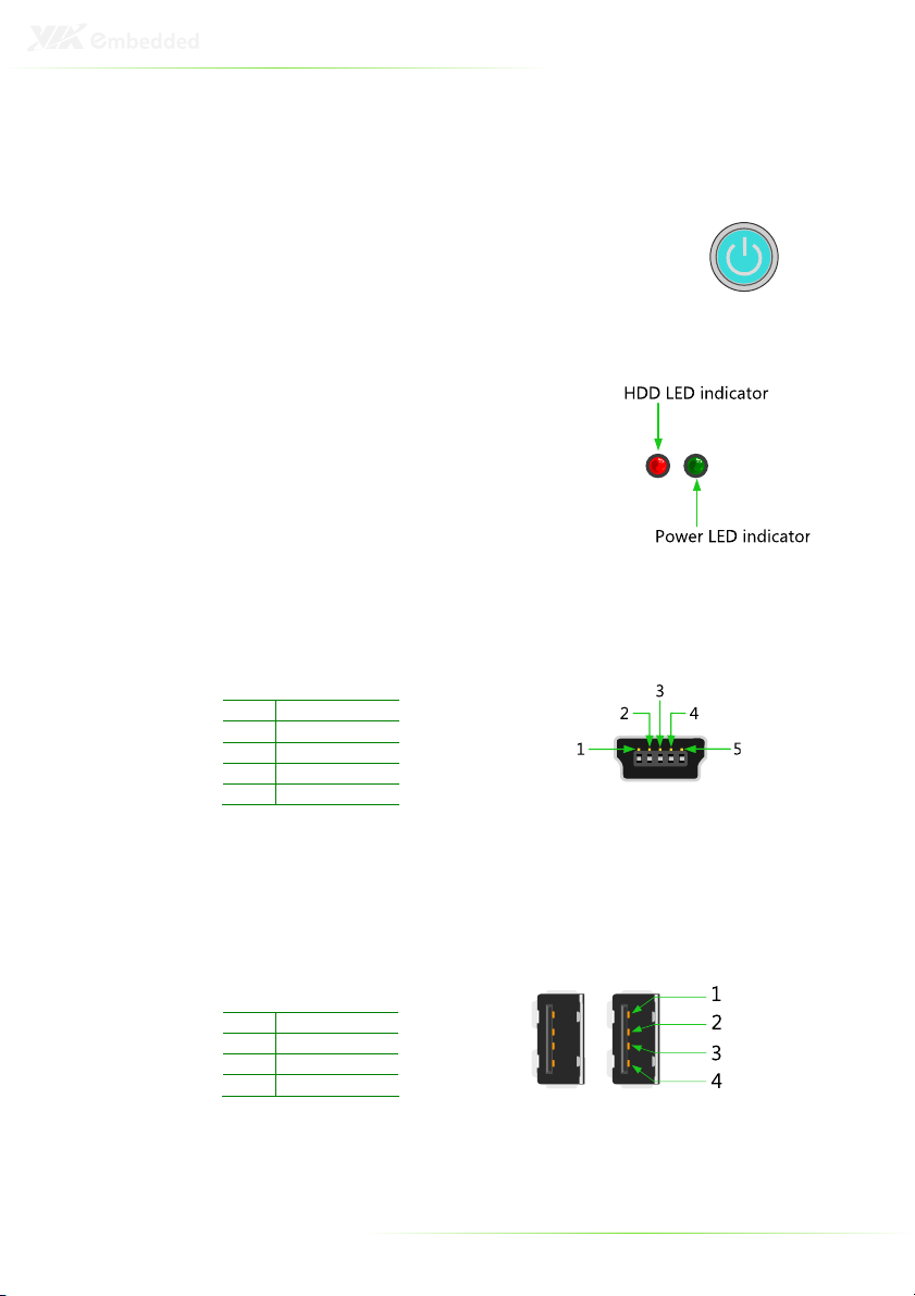
Power Button
The ARTiGO-A11 0 comes with a Power On/Off
button, that supports Soft Power-On/Off (Instant
Off or 4-Second Delay) and Suspend.
LED Indicators (Power LED and HDD LED)
There are two LEDs on the front face
plate that indicate the system status: The
Power LED indicates the power status
and flashes in green. The HDD LED
indicates the hard disk status and flashes
in red.
USB device port
The ARTiGO-A11 0 provides a USB device port in the front panel for
quick data transfer to another computer.
Pin
Signal
1 +5VU BD
2 U BDP-
3 U BDP+
4 U BID
5 GND
USB 2.0 ports
The ARTiGO-A11 0 provides four USB 2.0 ports (two in the front
panel, and two in the rear panel) for Plug & Play and hot
swapping access to external devices. The USB interface complies
with USB UHCI, Rev. 2.0.
Pin
Signal
1 VCC
2 U B_P0-
3 U B_P0+
4 GND
12
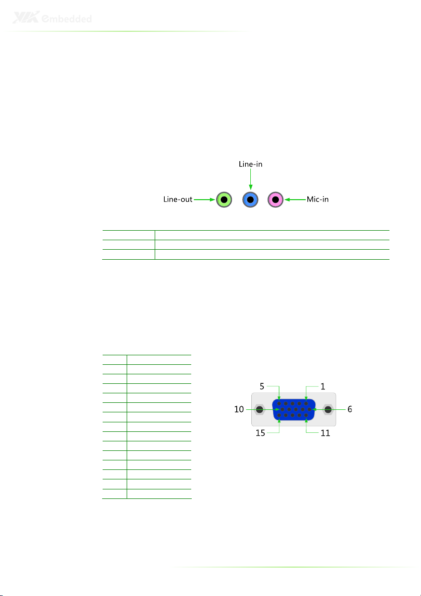
Audio Ports (Line-out Line-in and Mic-in)
The ARTiGO-A11 0 offers High Definition Audio through three
3. mm TRS jack connectors: Line-out, Line-in and Mic-in.
The Line-out jack is for connecting to external speakers or
headphones. The Line-In jack is for connecting to an external audio
device such as a CD player, tape player, etc. The Mic-in jack is for
connecting to a microphone.
Connector
Type
Line-out Phone Jack 3.5Ø 5P, 90 Degree, Female, color lime green, HIELDED
Line-in Phone Jack 3.5Ø 5P, 90 Degree, Female, color light blue, HIELDED
Mic-in Phone Jack 3.5Ø 5P, 90 Degree, Female, color light pink, HIELDED
VGA Port
The ARTiGO-A11 0 provides a high resolution VGA interface
through a 1 -pin D-sub female connector to support analog VGA
CRT monitors. It supports VGA and VESA, up to 1920 x 1200 @
60Hz resolution and up to 2 6 MB shared memory.
Pin
Signal
1 Red
2 Green
3 Blue
4 NC
5 GND
6 GND
7 GND
8 GND
9 NC
10 GND
11 NC
12 DDC DAT
13 H- YNC
14 V- YNC
15 DDC CLK
Table of contents


