Embedded amos-1000 User manual

user manual
AMOS-1000
Universal Compact
Chassis System, Supporting
Mini-ITX mbedded Boards
Revision
1.0
100
-
09
21
2009
-
1
8
38
II
Copyright and Trademarks
Copyright © 2009 VIA Technologies Incorporated. All rights reserved.
No part of this document may e reproduced, transmitted, transcri ed, stored in a
retrieval system, or translated into any language, in any form or y any means, electronic,
mechanical, magnetic, optical, chemical, manual or otherwise without the prior written
permission of VIA Technologies, Incorporated.
All trademarks are the property of their respective holders.
PS/2 is a registered trademark of IBM Corporation.
Disclaimer
No license is granted, implied or otherwise, under any patent or patent rights of VIA
Technologies. VIA Technologies makes no warranties, implied or otherwise, in regard to
this document and to the products descri ed in this document. The information provided
in this document is elieved to e accurate and relia le as of the pu lication date of this
document. However, VIA Technologies assumes no responsi ility for the use or misuse of
the information in this document and for any patent infringements that may arise from the
use of this document. The information and product specifications within this document are
su ject to change at any time, without notice and without o ligation to notify any person
of such change.
Regulatory Compliance
FCC-A Radio Frequency Interference Statement
This equipment has een tested and found to comply with the limits for a class A digital
device, pursuant to part 15 of the FCC rules. These limits are designed to provide
reasona le protection against harmful interference when the equipment is operated in a
commercial environment. This equipment generates, uses, and can radiate radio
frequency energy and, if not installed and used in accordance with the instruction manual,
may cause harmful interference to radio communications. Operation of this equipment in a
residential area is likely to cause harmful interference, in which case the user will e
required to correct the interference at his personal expense.
Notice
The changes or modifications not expressly approved y the party responsi le for
compliance could void the user's authority to operate the equipment.
Notice 2
Shielded interface ca les and A.C. power cord, if any, must e used in order to comply
with the emission limits.
Battery Recycling and Disposal
Only use the appropriate attery specified for this product.
Do not re-use, recharge, or reheat an old attery.
Do not attempt to force open the attery.
Do not discard used atteries with regular trash.
Discard used atteries according to local regulations.
Tested To Comply
With FCC Standards
FOR HOME OR OFFICE USE

III
Safety Precaution
Do’s
oAlways read the safety instructions carefully.
oKeep this User's Manual for future reference.
oAll cautions and warnings on the equipment should e
noted.
oKeep this equipment away from humidity.
oLay this equipment on a relia le flat surface efore setting
it up.
oMake sure the voltage of the power source and adjust
properly 110/220V efore connecting the equipment to the
power inlet.
oPlace the power cord in such a way that people cannot
step on it.
oAlways unplug the power cord efore inserting any add-on
card or module.
oIf any of the following situations arises, get the equipment
checked y authorized service personnel:
oThe power cord or plug is damaged.
oLiquid has penetrated into the equipment.
oThe equipment has een exposed to moisture.
oThe equipment has not worked well or you cannot
get it work according to User's Manual.
oThe equipment has dropped and damaged.
oThe equipment has o vious sign of reakage.
Don’ts
oDo not leave this equipment in an environment
unconditioned or in a storage temperature a ove 60°C
(140°F). The equipment may e damaged.
oDo not leave this equipment in direct sunlight.
oNever pour any liquid into the opening. Liquid can cause
damage or electrical shock.
oDo not place anything over the power cord.
oDo not cover the ventilation holes. The openings on the
enclosure protect the equipment from overheating
IV
Box Contents
1 x Screws package for oards
1 x Screws package for mount racket
1 x Ca le tie and tie mount package
1x Left wall mount racket
1x Right wall mount racket
1 x 2-pin Phoenix connector to DC jack ca le
1 x SATA HDD ca le
1 x Washer ru er package
We have carefully inspected the product mechanically and
electrically efore shipping. It should e free of cosmetic damage
and in perfect working order upon receipt. As you unpack the
product, check it for signs of shipping damage (e.g., damaged ox,
scratches, dents, etc). If it is damaged or it fails to meet the
specifications, notify our service department or your local sales
representative immediately. Also, please notify the carrier. Retain
the shipping carton and packing material for inspection y the
carrier. After inspection, arrangements will e made to repair or
replace the unit
Note:
Note:Note:
Note:
If any of these items are missing or damaged, contact your
distri utor or sales representative immediately.

V
Ordering Information
Model Number Description
AMOS-1000-1MZZA1 Em edded Chassis System for Mini-ITX
oards, with 120W DC to DC power oard,
rear Reserved Cutouts for 1 x DVI, 1 x DIO, 1
x D-su 26 pin connector, 4 x COM, 4 x USB
AMOS-1000-1MSZA1 Em edded Chassis System for Mini-ITX
oards, with 120W DC to DC power oard,
storage chassis, rear Reserved Cutouts for 1
x DVI, 1 x DIO, 1 x D-su 26 pin connector,
4 x COM, 4 x USB
AMOS-1000-1MRZA1 Em edded Chassis System for Mini-ITX
oards, with 120W DC to DC power oard,
riser chassis, rear Reserved Cutouts for 1 x
DVI, 1 x DIO, 1 x D-su 26 pin connector, 4
x COM, 4 x USB
AMOS-1000-1MSRA1 Em edded Chassis System for Mini-ITX
oards, with 120W DC to DC power oard,
storage chassis, riser chassis, rear Reserved
Cutouts for 1 x DVI, 1 x DIO, 1 x D-su 26
pin connector, 4 x COM, 4 x USB
Optional Accessories
Power Adapter
99G63-020 06 AC-to-DC adapter, 19V 90W
Power cables for power adapter
99G33-02058C power ca le, 180 cm, USA type
99G33-02057C power ca le, 180 cm, Europe type

VI
T
ABL OF
C
ONT NTS
1 Product Overview............................................................................................... 1
Key Features........................................................................................................... 2
Specification ........................................................................................................... 4
Power Supply ........................................................................................................ 5
Environment Specifications ............................................................................5
A OS-1000 Chassis Dimensions ................................................................ 6
The Front Plate...................................................................................................... 7
The Rear Plate........................................................................................................ 7
2 Accessories ............................................................................................................. 9
I/O Boards (Optional) .....................................................................................10
LPC-01/LPC-02...............................................................................................10
PUSB-01.............................................................................................................10
Cables......................................................................................................................11
LPC cable..........................................................................................................11
USB cable .........................................................................................................11
Power Cable ...................................................................................................12
Digital I/O cable............................................................................................12
DC Input connector converter cable.................................................13
Display odules (Optional)..........................................................................14
DVI-03................................................................................................................14
DVI-04................................................................................................................14
DVI-05................................................................................................................15
Cable for DVI modules ...................................................................................16
DVI cable..........................................................................................................16
USB odule (Optional)..................................................................................17
WLAN USB......................................................................................................17
Cable for WLAN module...............................................................................17
WLAN USB cable .........................................................................................17
3 Basic installation .................................................................................................19
Removing the top Cover of the Chassis.................................................20
Replacing the Power Board.........................................................................22
Installing the Hard Disk Drive......................................................................25
Installing the LPC-01 (or LPC-02) expansion module......................30
Installing the PUSB-01 expansion module............................................32
Installing the WLAN USB module.............................................................34
Installing the ainboard................................................................................36

VII
Installing the CF card or ini-PCI card....................................................38
Installing the Riser and PCI Cards ..............................................................40
Installing the CD Drive (Optional).............................................................45
Installing the Hard disk drive in Bottom Casing (Optional) ..........49
Installing the A OS-1000 Wall Bracket .................................................53
A Exploded Diagram ............................................................................................55
B Compatible ini-ITX boards ...................................................................57
C Cable Tie Location Illustration ......................................................................59

VIII

1
1
Product Overview

2
The A OS-1000 can be easily expanded to support application
specific requirements thorough its stackable sub-system chassis
expansion kits (riser chassis and storage chassis). The modularity
and expandability of the A OS-1000 chassis makes it ideally
suitable for diversified embedded system applications requiring the
combination of high processor performance, expandability, and
low costs (such as machine automation, and industrial plant and
cabinet integration).
An optional PCI riser card and numerous additional interfaces can
be easily installed to the A OS-1000 chassis through the PCI riser
sub-system chassis expansion kit. The storage sub-system chassis
expansion kit enables the A OS-1000 to support up to two
additional 2.5” HDD and a slim Optical Disk Drive (ODD). The
storage sub-system chassis expansion kit can be mounted to the
bottom of the A OS-1000 chassis.
The A OS-1000 chassis is built with a DC 120W power board
that accepts a wide range of DC power input from 12V to 24V.
Developers can also choose to replace the default power board
with the optional 1U ATX PSU. The modularity and expandability
of the A OS-1000 chassis and its stackable sub-systems, enables
longevity, easy maintenance and serviceability that protects the
customer’s investment.
KY FATUR S
U
UU
Universal
niversalniversal
niversal compact embedded chassis compatible with a wide
compact embedded chassis compatible with a wide compact embedded chassis compatible with a wide
compact embedded chassis compatible with a wide
selection of
selection of selection of
selection of ini
iniini
ini-
--
-ITX
ITXITX
ITX embedded boards
embedded boards embedded boards
embedded boards
•Open front I/O area makes it easy to support a wide variety of
I/O port configurations
Supports additional sub
Supports additional subSupports additional sub
Supports additional sub-
--
-system chassis expansion kits
system chassis expansion kitssystem chassis expansion kits
system chassis expansion kits
•An optional PCI riser sub-system chassis expansion kit can be
added to support up to two PCI cards.
•An optional storage sub-system chassis expansion kit can be
added to support up to two additional hard disks and one slim
optical drive.

3
Flexible configurations of I/O modules
Flexible configurations of I/O modulesFlexible configurations of I/O modules
Flexible configurations of I/O modules
•Abundant pre-punched removable I/O port cutouts at the rear
to support various I/O ports demands
•Available I/O modules include:
oLPC-01: four RS-232 ports
oLPC-02: two RS-232 and two RS-232/422/485
oPUSB-01: four ports Powered USB (5V power)
oDVI-03: DVI module (compatible with EPIA EK and EPIA EN)
oDVI-04: DVI module (compatible with EPIA SN)
odular power supply design
odular power supply designodular power supply design
odular power supply design
•Removable default power board supports DC 12V ~ 24V
•Supports 1U ATX power supplies (3.25" W x 1 5/8" H x 6" D)
WiFi networking option
WiFi networking optionWiFi networking option
WiFi networking option
•Optional WLAN module
•Designated mounting and antenna holes in A OS-1000
chassis
ultiple mounting solutions:
ultiple mounting solutions:ultiple mounting solutions:
ultiple mounting solutions:
•Secure wall mounting with special mounting bracket
•No-slip, shock resistant desktop mounting with special rubber
feet

4
SP CIFICATION
•Construction: heavy-duty steel
•Disk Drive Capacity: one internal 2.5 inch Hard Disk Drive bay
•LED Indicators on front panel: single-color LED for Power
(green) and HDD activity (red).
•Front I/O Interfaces: removable I/O plate
•Rear I/O Interfaces: pre-punched openings reserved for one D-
Sub 26-pin connector, one DIO port, one DVI port, four CO
ports, and four powered USB ports
•Cooling System: one 50 mm x 50 mm (13.0 CF ) cooling fan
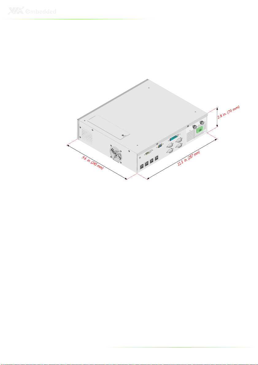
•Weight: 2.3 kg (5.07lb)
•Dimensions (W x H x D): 287 x 70 x 245 mm (11.3" x 2.8" x 9.6")

5
POW R SUPPLY
The A OS-1000 accommodates a DC 120W power board. The
detail specification is as follows:
DC Input
DC InputDC Input
DC Input
Input Minimum Nominal Maximum
Voltage 11.4V ~ 22.8V 12V ~ 24V 12.6V ~ 25.2V
Current 5.24A ~ 10.84A
DC Output Voltage
DC Output VoltageDC Output Voltage
DC Output Voltage
Input Minimum Nominal Maximum Maximum
Combined Power
+5V_SB 4.75V 5V 5.25V
+3.3V 3.14V 3.3V 3.47V
+5V 4.75V 5V 5.25V
+12V 11.4V 12V 12.6V
Power Good 4.75V 5V 5.25V
120W
DC Output
DC Output DC Output
DC Output Current
CurrentCurrent
Current
+5V_SB +3 3V +5V +12V -12V Power
Good
Maximum
Combined
Power
2A 6A 6A 5A 200mA 0.1A 120W
NVIRONM NT SP CIFICATIONS
•Temperature:
oOperating Temperature 0 to 45° C (32 to 113° F)
oStorage Temperature -20 to 65° C (-4 to 140° F)
•Relative Humidity: 0% ~ 90% @ 45° C (non-condensing)
•Vibration During Operation:
oUp to 1 Grms, IEC 60068-2-64, random, 5~500 Hz,1 oct./min.,
1hr/axis
•Shock During Operation:
o20 G, IEC 60068-2-27, half sine, 11ms duration (Operation)
6
AMOS-1000 CHASSIS DIM NSIONS
7
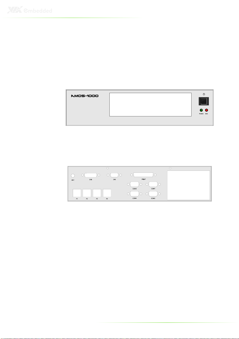
TH FRONT PLAT
The front panel features an open I/O window that can support
various I/O configurations. There is also a system Power Button
and two LEDs. When the system power is on, the POWER LED is
always Green. When the Hard Disk Drive (HDD) is transmitting
data, the red HDD LED blinks.
TH RAR PLAT
The rear face features reserved cutouts for:
•Four USB PlusPower ports (PUSB-01) - P1~P4
•Four CO ports (LPC-01 or LPC-02) – CO 1~CO 4
•One 9-pin D-sub (DIO) - DIO
•One DVI port (DVI-03 or DVI-04) - DVI
•One 26-pin D-sub – PRINT
•One Wireless LAN Antenna - ANT

8

9
2
Accessories

10
I/O BOARDS
(O
PTIONAL
)
LPC-01/LPC-02
Note:
Note:Note:
Note:
1.
LPC-01: Expansion module for four RS232 ports (5V or 12V)
2. LPC-02: Expansion module for two RS232 ports and two
RS232/422/485 ports (5V or 12V)
PUSB-01
Note:
Note:Note:
Note:
PUSB-01: Expansion module for four USB PlusPower (12V)
connectors

11
CABL S
LPC cable
Part # 99G33-120091
USB cable
Part # 99G33-19022
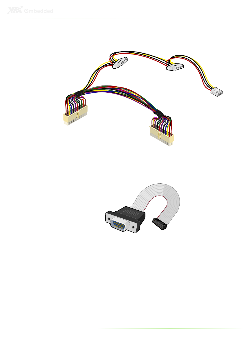
12
Power Cable
Part # 99G33-02073F
Digital I/O cable
Table of contents
Other Embedded Motherboard manuals


