EmberGlow DE18DBNGR/LPR Quick start guide

Convertible from Natural Gas to Propane/LP Gas
OWNER'S OPERATION AND INSTALLATION MANUAL
WARNING: If the information in this manual is not
followed exactly, a fire or explosion may result causing
property damage, personal injury or loss of life.
—
Do not store or use gasoline or other flammable vapors
and liquids in the vicinity of this or any other appliance.
— WHAT TO DO IF YOU SMELL GAS
• Do not try to light any appliance.
• Do not touch any electrical switch; do not use any
phone in your building.
• Immediately call your gas supplier from a neighbor’s
phone. Follow the gas supplier’s instructions.
• If you cannot reach your gas supplier, call the fire
department.
— Installation and service must be performed by a quali-
fied installer, service agency or the gas supplier.
INSTALLER: Leave this manual with the appliance.
CONSUMER: Retain this manual for future reference.
REMOTE CONTROL GAS LOG
VENTED DECORATIVE APPLIANCE
DE18DBNGR/LPR and DE24DBNGR/LPR
Listed By
Tested &
Vented Decorative Appliances
for installation in Solid Fuel
Burning Fireplaces

2
WARNING: Improper installation,
alteration, service, or maintenance can cause
injuryorpropertydamage. Refer to this manual for
correct installation and operational proced-
ures. For assistance or additional information
consult a qualified installer, service agency,
or the gas supplier.
WARNING:
only in a solid-fuel burning masonry or UL127
factory-built fireplace, constructed of noncom-
bustible material, and connected to a working
flue. (See page 5 for minimum flue opening.)
WARNING: This is a gas-fired appliance. It uses
from the room in which it is installed.
combustion and ventilat-
must be provided. Refer to the National
Z233.1/NFPA 54,Air for Com-
bustion and Ventilation .
WARNING: This product contains chemi-
the State of California to cause
cancer or birth defects, or other reproductive
WARNING: Keep flue open when operating
IMPORTANT: Read this owner’s manual carefully
andcompletely before trying to assemble, op-
erate, or service this log set. Improper use of
this log set can cause serious injury or death
from burns, fire, explosion, electrical shock,
and carbon monoxide poisoning.
DANGER: Carbon monoxide poisoning may
lead to death!
Carbon Monoxide Poisoning:Early signs of carbon
Natural and Propane/LP Gas: Natural and propane/LP
gases are odorless. An odormaking agent is added to the
gas. The odor helps you detect a gas leak. However,
the odor added to the gas can fade. Gas may be present
even though no odor exists.
Make certain you read and understand all warnings.
Keep this manual for reference. It is your guide to safe
and proper operation of this log set.
WARNING: Any change to this log set or its con-
trols can be dangerous.
1. This appliance, as supplied, is only for use with the
type of gas indicated on the rating plate. This appliance
is convertible for use with propane/LP.
Safety ............................................................... 2-3
Product Identification ........................................... 3
Local Codes .........................................................4
Unpacking ............................................................4
Product Features ................................................. 4
Operation
................... ...........
.. .............................
Inspecting Burners ............................................
Cleaning and Maintenance ................................12
Service Hints .....................................................
Technical Service ...............................................
Troubleshooting ...........................................12-13
Replacement Parts ......................................14-15
Warranty ............................................ Back Cover
SAFETY
adjustment,
This appliance is for installation
air (oxygen)
Provisions for adequate
ion air
Fuel Gas Codes, ANSI
cals known to
harm.
unit.
monoxide poisoning resemble the flu, with headaches,
dizziness, or nausea. If you have these signs, the log
set may not be working properly. Get fresh air at once!
Have log set serviced. Some people are more affected
by carbon monoxide than others. These include pregnant
women, people with heart or lung disease or anemia,
those under the influence of alcohol, and those at high
altitudes.
2. What to do if you smell gas:
Shut off gas supply.
• Do not try to light any appliance.
Do not touch any electrical switch; do not use any
neighbor’s
phone. Follow the gas supplier’s instructions.
3. Never install the log set:
• In a recreational vehicle
• Wherecurtains, furniture, clothing, or other flammable
objects are less than 42" from the front, top, or sides
o f the log se t
• In high traffic area
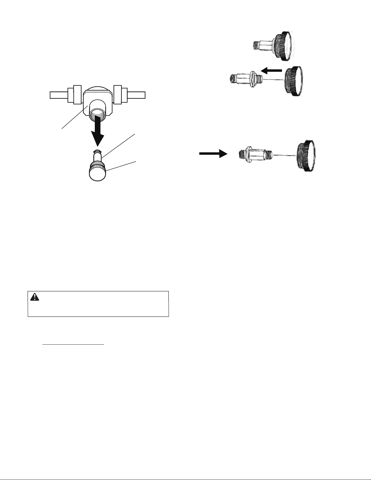
(see Conversion
Instruction, P.7 )
Installation
•
• Immediately call your gas supplier from a
•
phone in your building.
• In windy or drafty areas
4- 9
................ ................ .......
........................................... 10
11
12
12
• If you cannot reach your gas supplier, call the fire
department.

3
5. You must operate this log set with fireplace
in place and fully closed. Unless provided by other
means, fireplace doors or screens shall haveopen-
ings for introduction of combustion air.
6. This log set is designed to be smokeless. If logs
ever appear to smoke, turn off appliance and call a
qualified service person.
Note: During initial operation, slight smoking could
occur due to log curing and the burning off of man-
ufacturing residues. You may wish to add more
ventilation by opening a window.
7. To reduce the creation of soot, follow the “Cleaning
and Maintenance” instructions on
,page 13.
8. Do not allow fans to blow directly into the fireplace.
Avoid any drafts that alter burner flame patterns. Ceiling
fans can create drafts that alter burner flame patterns.
Altered burner patterns can increase sooting.
Continued
9. Do not use a blower insert, heat insert or
other accessory not approved for use with this log
set.
-exchanger
10.
The installation and provisions for combustion and vent-
ilation air must conform with the National Fuel Gas
Codes, ANSI Z233.1/NFPA 54, Air for Combustion and
Ventilation.
11. Do not run log set:
•where combustible materials, gasoline and other
flammable vapors and liquids are used or stored
• under dusty conditions
12. Do not burn solid fuel in the fireplace after installing the log
set. Do not use this log set to cook food or burn paper or
other objects.
13. Log set becomes very hot when in use. Keep children and
adults away from hot surface to avoid burns or clothing
ignition. Log set will remain hot for a time after shut-down.
Allow surface to cool before touching.
14. Carefully supervise young children when they are in
the room with log set.
15. Do not use this appliance if any part has been under
water. Immediately call a qualified service technician
to inspect the appliance and to replace any part of the
control system and any gas control which has been
under water.
16. To help prevent breakage, new logs must be broken-in
(see “Curing Logs” page 12).
17. Turn log set off and let cool before servicing, installing,
or repairing. Only a qualified service person should in-
stall, service, or repair log set.
18. Provide adequate clearances around air openings.
PRODUCT IDENTIFICATION
Figure 1 - Product Identification - (Log Position May Vary with Model)
SAFETY
screens
Burner Tube
Heat Shield
Control Knob
Burner Pan

LOCAL CODES
Install and use log set with care. Follow all local
codes. In the absence of local codes, use the
latest edition of The National Fuel Gas Code ANSI-
Z223.1/NFPA 54*..
*Available from:
American National Standards Institute, Inc.
1430 Broadway
New York, NY 10018
National Fire Protection Association, Inc.
Batterymarch Park
Quincy, MA 02269
PRODUCT FEATURES
UNPACKING
CAUTION:Donotremovethe metaldataplatesfrom the
burner pan. The data plates contain important warranty
and safety information.
1. Remove logs, hearth kit, pan materials,
and hardware from carton.
2.
Remove all protective packaging applied
to logs and base for shipment.
3.
Check appliance for any shipping damage.
If itisdamagedcallSure Heat Manufacturing
at 1-800-229-5647 for replacement parts
before returning to dealer.
REMOTE CONTROL SAFETY VALVE/PILOT
Thisunitisprovidedwitha remotegas controlvalve
which is connectedtoa wireless transmitter/rec-
eiver set, allowing safe operation from anywhere
in the room.
Unit is tested and approved to ANSI Z21.60 as a vented
decorative appliance. It is supplied with the parts and ins-
tructions to convert to propane/LP gas use.
APPROVALS
4
WARNING: The Massachusetts State
Board requires all installations be perform-
ed by a Licensed Plumber or Gas Fitter. Mas-
sachusetts state code requires all vent
dampers be welded open or removed.
CAUTION: Do not remove the data plates
attached to the burner pan. The data plates
contain important warranty and safety informat-
WARNING:Beforeinstallingin a solid fuel
burning fireplace,the chimneyflueandfirebox
mustbe cleaned of soot, creosote, ashes and
loose paint by a qualified chimneycleaner.
Creosotewilligniteifhighlyheated. Adirtychim
-
ney fluemaycreateanddistribute soot within
the house. Inspect chimney flue for damage.
NOTICE:Installation, service,and repair of this appliance must
be performedbyaqualifiedinstaller, service agency, comp-
any or gas supplier, experienced with this type of gas app-
liance. Only factory authorized components should be used,
in accordance with the manufacturer’s instructions and all
codes and requirements of the authority having jurisdiction.
Any modifications to this kit, or useofunauthorizedcompon-
ents or accessory items will void the manufacturer’swarranty,
and may resultin ahazardous condition.
FLUE OPENING SPECIFICATIONS
Note:Thisvented appliancemust beinstalled only in a
solid-fuel burning fireplace with a working flue and con-
structed of noncombustible material.
ion.
INSTALLATION
VENTING SPECIFICATIONS FOR
INSTALLATION
The fireplace chimney flue and vent must be draft-
ingproperly.To checkthe ventfor proper drafting:
Light a tightly rolled newspaper on one end and
place it at the inside front edge of the fireplace.
Observe the smoke and be sure the vent is prop-
erly drawing it up the chimney.Ifthe smokespills
outinto theroom, extinguishthe flameandremove
anyobstruction until proper venting is achieved.
The chimney flue damper must be fixed open to provide a
minimum of 81 sq. in. of free air opening during operation
of this log set. A multipurpose damper clamp is provided
to fix the damper in position.
The minimum flue sizes shown in Figure 2 arebased on
a6' chimneyheight usinground pipe. Your minimum flue
size will vary based oninput rateand chimneyheight. Refer
tothe National Fuel Gas Code ANSI Z223.1/NFPA 54,
Section 6.6, for details.

Continued
The charts in Figure 2 indicate technical inform-
ation regarding the installation of your gas log set.
Please make sure that all of the specifications
shown are applicable before installation is attempt-
ed.
The fireplace must include a working flue and venting
system with the minimum openings shown in the
Figure 2.
CHECK GAS TYPE
Use only natural gas. If your gas supply is not nat-
ural gas, you must convert the appliance to propane
/LP. Follow the instructions on page 7.
-
If the fireplace does not have a gas supply shutoff
valve, one must be installed.
INSTALLATION
Figure 2 - Technical Information Charts
BURNER ORIFICE
LOG
SIZE
NATURAL PROPANE/LP
In. Num. In.
FUEL PRESSURE
SPECIFICATIONS (W.C.)
Inlet Manifold*
NG 5.5"-10.5" 3.5"
LP 11"-13" 10"
* ± .2"
MINIMUM FIREBOX SIZE
LOG
SIZE
FRONT
WIDTH
BACK
WIDTH* DEPTH HEIGHT
MINIMUM
FLUE SIZE
8" dia.
18,24" 35 3/4"17" 15 1/2"18"
DESCRIPTION
Btu\Hr Input
Natural Gas
Btu\Hr Input
Propane Gas
60,000
24" Dual Burner 60,000
INSTALLING DAMPER CLAMP
Secure the damper stop clamp provided to the leading
edge of the damper as shown in Figure 3. If for any rea-
son this clamp doesn't work on your fireplace, another
suitable clamp or permanent stop must be installed, or
the damper blade must be cut or removed.
Damper
Damper
Clamp
Damper
Manufactured FireplaceMasonry Fireplace
Damper
Clamp
Damper
Figure 3 - Attaching Damper Clamp
CONNECTING TO GAS SUPPLY
WARNING: A qualified service person must
local codes.
connect log set to gas supply. Follow all
Installation Items Needed
Before installing log set, make sure you have
the items listed below.
• piping (check local codes)
• sealant (resistant to propane/LP gas)
•equipment shutoff valve
• adjustable (crescent) wrench or pliers
• sediment trap
• tee joint
• pipe wrench
CAUTION: Use only new, black iron or
steel pipe. Internally-tinned copper tubing may
be used in certain areas. Check your local
codes. Use pipe of 1/2" diameter or greater to
allow proper gas volume to log set. If pipe is too
small, undue loss of
volume will occur.
Installation must include an equipment shutoff valve with
"T" style handle, gas union and, for propane/LP gas only,
a plugged 1/8" NPT pressure tap. Locate NPT tap within
reach for test gauge hook up. NPT tap must be upstream
from log appliance
(see Figure 4).
CONNECTING TO GAS SUPPLY
Continued
IMPORTANT: Install equipment shutoff valve in an ac-
cessible location. The equipment shutoff valve is for
turning on or shutting off the gas to the appliance.
Apply pipe joint sealant lightly to male NPT threads. This
will prevent excess sealant from going into pipe. Excess
sealant in pipe could result in a clogged burner injector.
WARNING: Use pipe joint sealant that is resistant
to liquid petroleum (LP) gas.
5
18,24” .144 #27 .089” #43
Num.

We recommend that you install a sediment trap in
the supply line as shown in Figure 4. Locate sediment
trap where it is within reach for cleaning. Install in piping
system between fuel supplyandheater. Locate sed-
iment trapwhere trapped matter is not likely to
freeze. A sediment trap traps moisture and contamin-
ants. This keeps them from going into log set controls.
If sediment trap is not installed or is installed wrong,
log set may not run properly.
INSTALLATION
Figure 4 - Gas Connection
3" Minimum
From Gas
Meter (5"
W.C.** to
10.5" W.C.
Pressure)
CSA Design-Certified
Equipment Shutoff Valve
With 1/8" NPT Tap*
Approved Flexible
Gas Hose (no longer
than 36" if required by
local codes)
Tee Pipe Cap
Joint Nipple
Sediment Trap
* Purchase the optional CSAdesign-certified equipment
shutoff valve from your dealer. **Minimuminletpressure
forpurposeofinput adjustment.
6
CHECKING GAS CONNECTIONS
WARNING:Test allgas piping and connections, in-
ternal and external to unit, for leaks after installing
or servicing. Correct all leaks at once.
WARNING: Never use an open flame to check
for a leak. Applyanoncorrosiveleakdetection fluid to
all joints. Bubbles forming show a leak. Correct all
leaks at once.
PRESSURE TESTING GAS SUPPLY PIPING
SYSTEM
Test Pressures In Excess Of 1/2 PSIG(3.5 kPa)
1. Disconnectlogsetanditsindividualequipmentshut-
offvalvefrom gassupplypiping system.
-
2. Capoffopenendofgaspipewhereequipment shut-
off valve was connected. -
3. Pressurizesupply pipingsystembyeither using com-
pressedairoropeningmaingas valve located on or
near gas meter.
Continued 4. Check all joints of gas supply piping system.
Apply a noncorrosive leak detection fluid to all
joints. Bubbles forming show a leak.
-
5. Correct all leaks at once.
6. Reconnect log set and equipment shutoff valve
to gas supply. Check reconnected fittings for
leaks.
Test Pressures Equal To or Less Than 1/2
PSIG (3.5 kPa)
1. Close equipment shutoff valve (see
Figure 5).
2. Pressurizesupply pipingsystembyeither using
compressedairoropeningmaingas valve locat-
ed on or near gas meter.
3. Check all joints from gas meter to equip ment
shutoff valve (see Figure 5). Apply a noncorr-
osive leak detection fluid to all joints. Bubbles
forming show a leak.
-
4. Correct all leaks at once.
Figure 5 - Checking Gas Joints
Gas Meter
Equipment
Shutoff Valve
HEARTHPAN INSTALLATION
If usingpropane/LP gas, see Propane/LP
Gas Conversion page 7 before installing
hearth pan.
1. Place the burner pan assembly in the center
of the fireplace floor. Make sure the front of
pan faces forward.
2. Thread the gas supply fitting to the fire place
gas supplypipe. Adjust to most convenient
position.
3. Install the gas connector tube to the gas supply
adapter. Carefully shape tube and attach to gas
inlet fitting (see Figure 6). Be careful not to
cause kinks in tube.
4. Test for leaks following instructions under
Testing Burner for Leaks , page 8.

INSTALLATION
Continued
5. Retighten andadjust the location of the
gas control as necessary. The gas control
should be level, with the control knob to the
front.
Figure 6 - Installing Inlet Fitting and Gas
Connector Tube (Heat Shield Removed
for Clarity)
Gas Control Valve
Propane/LP Gas Conversion
To convert to Propane/LP gas, the regulator pres-
sure must be reset. Also, burner inlet fitting and
pilot orifice must be replaced. The Propane/LP
burnerinletfittingis suppliedwith the orifice installed
Burner Inlet Fitting
1. Remove pilot assembly burner pan by remov-
ing two screws on bracket.
2. Unthread control valve and burner inlet fitting
from burner tube by turning valve counterclock
wise (seeFigure 7) .
Remove Natural Gas inlet fitting from control
valve assembly
(seeFigure 8).
DO NOT remove orifice from this fitting. The
Propane/LP burnerinlet fitting is provided in
the hardware kit (seeFigure 8).
3.
Be sure to use the correct orifice for your app-
liance.Theorificekitincludedwiththis appli-
ance contains an orifice installed in an air
mixer fitting.
4. Using thread sealant (resistant to the action
of propane/LP gas) on smaller end of fitting,
screw the burnerinlet fitting into outlet side of
gas control. Tighten using a wrench.
5 . Rethread valve and fitting assembly into
burner tube until fully threaded and level with
burnerpan. Reattach valve cover with two
(2) screws. NATURAL GAS
COMPONENTS
Burner Inlet Fitting
for Natural Gas
Figure 7 - Burner Inlet Fitting and Pilot Prifice
Natural Gas
Pilot Orifice
Figure 8 - Burner Inlet Fittings shown with orifice
NATURAL
GAS
FITTING
PROPANE/LP
GAS FITTING
Orifice for
Natural Gas Injector for
Propane/LP Gas
7
NG to LP Regulator Selection
The appliance regulator can be converted from Natural
Gas to LP/gas. If connecting to a Propane gas system,
regulator must be switched prior to use. Follow thethe
steps below to select Propane/LP gas.
1. Carefully remove the logs from the burner assembly.
2. Make sure gas is turned off to the unit and disconnect
burnerassemblyfromgasline.Removeburnerassemb-
ly from fireplace or firebox.
3. Locatetheregulatorcapontheapplianceregulator(see
Figure 9). Unscrew by hand and remove the cap from
the regulator. The pressure selecting screw is attached
to the regulator cap. The pressure selecting screw is
supplied in the Natural Gas position.
4. Unscrewandremovethepressureselecting screw
from the regulator cap (see Figure 9 ).
WARNING: Only a qualified installer or
service technician can perform gas con-
version and connection to gas supply.
SELECTING GAS TYPE
This appliance can be used with Propane/LP gas or
Natural Gas. It is shipped from the factory adjusted
for use with Natural Gas. Main burners are equipped
with fixed orifices, located at the inlet of the burner
pan (see Figure 7).
for your log set.
Retain the removed Natural Gas components
for future use.
Pilot Orifice Replacement
Disconnect the pilot supply tube from the pilot (See
Figure 7). Replace the pilot orifice with the Propane/LP
pilot orifice included with the Gas conversion kit. Retain
the removed orifice for future use.

INSTALLATION
Continued
5. Turn pressure selecting screw over and reinstall it
in regulator cap (see Figure 10-11).This will set the
pressure selecting screw to the LP/Propane gas
ition. Makethe pressure selecting screw is installed
tightly to the regulator cap.
6. Replace the regulator cap on the appliance regulator.
Figure 9 - Gas Selection Valve Knob and
Regulator Cap
Regulator
Cap
Pressure
Selecting
Screw
Appliance
Regulator
Figure 10 - Removing Regulator Cap from Pressure
Selecting Screw
Figure 11 -
Turning Pressure Selecting Screw Over/
Attaching to Regulator Cap – LP/Propane
Gas Position
1. Generously apply soapy solution to all connect-
ions.
WARNING: Never check for gas
leaks with open flame.
2. Light burner with shutoff valve no more than half
open and holding a match slightly in front of pan
(see
Lighting Instructions, page 11).
3. Inspect all connections for bubbles, raw gasodor,
orflamefromanyareaotherthan the burner (leaks).
If leaks are detected, shut off gas valve immediately.
tighten, or reassemblelooseconnection(s)usingpipe
joint compound until burner system is leak free.
Testing Burner for Leaks
4. When burner is tested and leak free, observe
individual tongues of flame on burner (from ports).
reaming ports with a modified paper clip or other suit-
able tool. When finished testing, turn gas shutoff
valve to OFF to extinguish all flames.
-
1. Open bag of burner media material (vermiculite
if set for LP/Propane) and spread it evenly
across burner pan to the top. You may over-
flow front and sides of pan to cover entire pan.
Do not cover valve.
2. Open glowing embers and evenly cover burner
media material (or vermiculite) in burner pan.
Adding Burner Media Material
Installing Grate and logs
Slide two rear log grate steps over two outer
horizontal supports on the grate as shown
in image 2 on page 9.
Install logs onto the grate by following the rest
of the instructions in on pages 9 and10.
1.
2.
8
NOTE: In order to convert the unit from LP Gas, back to Natural Gas, follow steps 1 through 3 under “Burner
Inlet Fitting” on page 7.Follow steps 1 through 6 under the heading of “NG to LP Regulator Selection” on
this page. Images 11 and 12 will occur in reverse order.
Note: Make sure that all ports are clear and prod-
ucing flame evenly across burner.If any ports appear
blocked, clear them by removing burner manifold and

Proper Log Placement for Vented Gas Log
Models DE18DBNGR/LPR AND DE24DBNGR/LPR
Log Stand-Offs
Log #1
Log #2
Log #4
Log #3 Log #5
Log #6 Log #7 Complete With
Embers
9
If you have any questions, please call (800) 229-5647

FOR YOUR SAFETY
READ BEFORE LIGHTING
WARNING: Keep flue open when operating unit.
WARNING: If you do not follow these instruct-
ions exactly, a fire or explosion may result caus-
ing property damage, personal injury or loss of life.
A. This appliance has a pilot which must be lighted
by hand.When lighting the pilot, follow these
instructions exactly.
B. BEFORE LIGHTING smell all around the app-
liance area for gas. Be sure to smell next to the
floor because some gas is heavier than air and
will settle on the floor.
WHAT TO DO IF YOU SMELL GAS
•Do not try to light any appliance.
• Do not touch any electric switch; do not use
any phone in your building.
• Immediately call your gas supplier from a
neighbor’s phone. Follow the gas supplier’s in-
structions.
• If you cannot reach your gas supplier, call the
fire department.
C. Use only your hand to push in or turn the gas
control knob. Never use tools. If the knob will
not push in or turn by hand, don’t try to repair it,
call aqualified servicetechnician or gas supplier.
Forceorattempted repair mayresult in a fire or
explosion.
D. Do not use this appliance if any part has been
under water.Immediately call a qualified service
technician to inspect the appliance and to replace
any part of the control system and any gas control
which has been under water.
LIGHTING INSTRUCTION
1. STOP!Read the safety information on the
left side of this page.
2. Make sureequipment shutoff valve is fully
open.
3. Press in and turn control knob clockwise
to the OFF position.
4. Wait five (5) minutes to clear out any gas.
Thensmell for gas, includingnear the floor.
If you smell gas, STOP! Follow “B” in the safety
information, at left. If you don’t smell gas, go to
the next step.
5. Press in and turn control knob counter clockwise
-
to the PILOT position.
Press in control knob for five (5) seconds (see
Figure 13).
Note: You mayberunning this log set for the first
time after hooking up to gas supply. If so, the con-
trol knobmayneed to be pressed in for 30 seconds
or more. This will allowair to bleed from the gas
system.
6. With controlknobpressed in, use a match or
grill lighter tolight pilot. Visually locate the pilot
(see Figure 12) on the edge of the burner pan
to look for flame.If needed, repete operation
until the pilot lights.
Figure 13 - Control Knob Location
ON
TOLIP
Control Knob
If the pilot will not stay lit after several tries, turn
the gas control knob to "OFF"and call your service
technician or gas supplier.
7.
8. Keep control knob pressed in for 30 seconds
after lighting pilot. After 30 seconds, release
control knob.
-
•
If control knob does not pop out when released,
contact a qualified service person or gas sup-
plier for repairs.
Note: If pilot goes out, repeat steps 3
through 8.
Figure 12 - Thermopile and Pilot
Pilot
Thermopile
10
OPERATION

LIGHTING INSTRUCTION
Continued
9. Slightly push in and turn control knob counterclockwise-
to the ON position.
10.To leave pilot lit and shut off burners only:
Turn control knob clockwise to the PILOT
position, or set selector switch in the OFF position.
TO TURN OFF GAS
TO APPLIANCE
Shutting Off Appliance
1. Slightly push in and turn control knob clockwise
to the OFF position.
2. Close equipment shutoff valve.
CURING
THE LOGS
During the 2-3hourappliance break-inperiod, you may
detect an odor from the appliance as the various paints
and compounds used in the manufacturing of this log
set cure.
Hand Held
Remote
NOTICE: You must light the pilot before using the
hand-held remote control unit. See Lighting
Instructions, page 11.
After lighting, let pilot flame burn for about one minute.
Turn control knob to ON position. Slide the selector
switch on the remote receiver to the REMOTE
position.
Note: The burner may light if hand-heldremote was
on when selector switch was last turned off. You
can now turn the burneronand off with the hand-
held remote control unit.
IMPORTANT: Do not leave the selector switch in the
REMOTE or ON position when the pilot is not lit.
This will drain the battery.
INSPECTING BURNERS
Check pilot flame pattern and burner flame patterns
often.
PILOT FLAME
The pilot assembly is factory preset for the proper
flameheight. Alterations may have occurred during
shipping and handling. The pilot is located on the
back right hand side of the burner.
The thermocouple should be fully enveloped in the
flame. The flame should not be lifting off of the
thermocouple element.
•Turn the adjustment screwmarkedpilot clockwise
to decrease or counterclockwise to increase the
flame to proper size (see Figure 14).
Do not attempt to remove the adjustment screw.
If your pilot assembly does not meet these re-
quirements:
•SeeTroubleshooting, pages 12-13
Thermocouple
Pilot
Figure 13 - Correct Pilot Flame Pattern
BURNER FLAME PATTERN
Burnerflames will be steady; not lifting or floating.
Flames should go up through the middle of logset.
Flames should not "spill" to the edges of the pan or
sides of the logset.
Figure 15 shows a typical flame pattern. If burner
flame pattern differs from that described:
Pilot
Adjustment Screw
Figure 14 - Locating Pilot Adjustment Screw
• Turn appliance off (see To Turn Off Gas to Appli-
ance, this page).
• See Troubleshooting , page13.
Figure 15 - Typical Flame Pattern
This is a normal and temporary situation that is not
cause for alarm. However, you may want to provide
extra ventilation to the room during this time.
11

CLEANING AND MAINTENANCE
• Keep the area around the log set clean and clear of
debris.
• Occasionally, you may use a soft bristle brush to
clean logs.
• Periodically inspect the air mixer and burner tube for
foreign matter blocking the air inlet and flame holes.
SERVICE HINTS
When Gas Pressure is Too Low
• Once every year a qualified agency or certified chim-
ney sweep should examine and clean the venting
system of the fireplace.
• pilot will not stay lit
• burners will have delayed ignition
•heater will not produce specified heat
• propane/LP gas supply may be low
Ifyoususpect your gas pressure is too low, contact
your gas providerer and request that it be tested.
WARNING: Turn off log set and let cool before servicing. Only a qualified service person should service
and repair log set.
TROUBLESHOOTING
OBSERVED PROBLEM POSSIBLE CAUSE REMEDY
When attempting to ignite with a
match,pilot will not light.
1.Gas supply turned off or
equipment shutoff valve
closed.
2.Control knob not in PILOT
position.
3.Control knob not pressed in
while in PILOT position.
4.Air in gas lines when in-
stalled.
5.Pilot adjustment screw
closed.
6.Pilot is clogged.
7.Low/incorrect gas pressure.
1.Turn on gas supply or open
equipment shutoff valve.
2.Turn control knob to PILOT
position.
3.Press in control knob while
in PILOT position.
4.Continue holding down con
-
trol knob. Repeat igniting op-
eration until air is removed.
5.Adjust pilot flame for ap -
proximately 2" blue flame.
6.Clean pilot (see Cleaning
and Maintenance, above)
or replace pilot assembly.
7.Check/replace gas regulator.
Pilot lights but flame goes
out when control knob is
released.
1.Control knob not fully
pressed in.
2.Control knob not pressed in
long enough.
3.Equipment shutoff valve not
fully open.
1.Press in control knob fully.
2.After pilot lights, keep con-
trol knob pressed in 30
seconds.
3.Fully open equipment shut-
off valve.
4.Pilot flame not touching
thermocouple, which al-
lows thermocouple to cool,
causing pilot flame to go
out. This problem could be
caused by one or both of
the following:
A) Low gas pressure
B) Dirty or partially clogged
pilot.
5.Thermocouple connection
loose at control valve.
6.Thermocouple damaged.
7.Control valve damaged.
4.A) Contact local natural gas
company.
B) Clean pilot (see Cleaning
and Maintenance, above)
or replace pilot assembly.
5.Hand tighten until snug, then
tighten 1/4 turn more.
6.Replace thermocouple.
7.Replace control valve.
Burner does not light after
pilot is lit.
1.Burner orifice clogged.
2.Inlet gas pressure is too
low.
3.Thermocouple leads dis -
connected or improperly
connected.
1.Clean burner orifice.
2.Contact local natural or
propane/LP gas company.
3.Reconnect leads.
13
TECHNICAL SERVICE
For operational questions or technical service, call toll free (800) 229-5647. Be sure to have your model
number availible when calling.

Remote does not function. Batteryis notinstalled. Battery power
may be low. Replace9-voltbatteriesinreceiver
and/or remote control.
Burner flame is too low or
ing (see Figure 2, page 5).
1.Incorrect gas supply or pressure. 1.Checkfor propergas supply
pressure.too high. 2.Blocked burner orifice or burner
manifold ports. 2.Free burner orifice and
manifold ports of any burrs,
paint, or other blockage.
Burner is excessively noisy.
(Note: The movement and
combustion of gas will cre
ate low, unavoidable levels
of noise.)
1.Passage of air/gas across irregular
2.Excessive gas pressure on natural
gas units.
surfaces. 1.Relieve any tight bends or
kinks in gas supply line.
2.Have inlet gas pressure
checked by a qualified ser
vice person.
3.
Improper burner orifice size.
3.Verifyproperburnerorificesiz--
Log set is smoking/sooting
excessively.
(Note: It is natural and un-
avoidable for vented gas log
sets to produce moderate
levels of carbon (soot) where
flames contact the logs. This
isespeciallytruewithpropane/
LP gas.)
1.Poor fuel quality.
2.Fireplace venting system not
drafting properly.
3.Excessive flame impingement
or blockage.
4.
Improper fuel/air mixture.
5.
Excessivegas supply/pressure.
1. Contact local natural or
propane/LP gas company.
2. Adjust damper wide open
and/or have fireplace and
venting professionally
cleaned and checked.
3. Separate the logs to allow
more flame passage.
4. Remove any foreign items
from the flame pattern and/
or check for proper orifice
sizing.
5. Preheat flue in very cold
weather.
OBSERVED PROBLEM POSSIBLE CAUSE REMEDY
TROUBLESHOOTING
Continued
Delayed ignition burner. 1.Pilot flame needs adjust -
ing.
2.Wrong pilot orifice for gas
type.
1.
Adjust pilot flame for ap -
proximately 2" blue flame.
2.
Replace pilot orifice.
Log set produces a clicking/
ticking noise just after burner
is lit or shut off.
Metal expanding while
heatingor contractingwhile
cooling.
This is normal with most log
sets. If noise is excessive,
contact qualified service
person.
Log set produces unwanted
odors. 1.Log Set burning vapors
frompaint,hairspray,glues,
cleaners, chemicals, new
carpet, etc. (See IMPOR -
TANT statement below.)
2.Gas leak. See Warning
statement below.
1.Openfluetomaximum.Stop
usingodorcausing products
while log set is running.
2. Locate and correct all leaks
(see CheckingGas Connec-
tions, page 6).
Gas odor even when control
knob is in OFF position. 1.Gas leak.See Warning
statement below.
2.Control valve defective.
1. Locate and correct all leaks
(see CheckingGas Connec -
tions, page 6).
2.Replace control valve.
WARNING: If you smell gas:
•Shut off gas supply.
•Do not try to light any appliance.
•Do not touch any electrical switch; do not use any phone in your building.
•Immediately call your gas supplier from a neighbor’s phone. Follow the gas supplier’s instructions.
•If you cannot reach your gas supplier, call the fire department.
IMPORTANT: Operating log set where impurities in air exist may create odors. Cleaning supplies, paint, paint
remover, cigarette smoke, cements and glues, new carpet or textiles, etc. create fumes. These fumes may mix
with combustion air and create odors. These odors will disappear over time.
14

DE18,24DBNG(LP) PARTS
L
15
18
2
16
13
6
10
17
14
11
7
5
9
12
1
83
4
28
20
19
LP Conversion
21
22
23
19 27
25
26
14
24
28

KEY NO. PART NO. DESCRIPTION QTY.
1. Burner Pan 1
2. Burner Tube 1
3. Orifice Holder, Natural Gas
4. Orifice, Natural Gas
5. Orifice, Propane/LP Gas
Orifice, Propane/LP Gas6.
7.
8.
Washer
Pal Nut
9.
10.
Elbow, “Street” 3/8”NPT
Valve, Remote “ON/OFF”
11.
Pipe, “Close” 3/8” NPT
12.
Regulator, Dual Fuel
13.
Fitting, 3/8” NPT X 3/8” Flare14.
Connector, 3/8” Tube
15.
Fitting, 3/8” X 1/2” NPT Female
17. Screw #6 32 x 1/2”Screw #6 32 x 1/2”
SBNCJ00365A
RCOCB00002A
RCORJ00003A
RMH-120-00085B
RMH-120-90955
RMH-120-00084B
RMH-120-00324
RCODZ00145A
RMH-120-00069
RMH-120-AF1010
RMH-120-90860
RCOZZ00568A
RMH-120-00050
KHH-ACT16
Heat ShieldRMH-120-RVS304
16.
20.
18. Pilot Assembly, NGRCOZZ00495B
19. Screw, Sheet Metal #6 x 1/2”RMH-120-00570
21. Grate, Vented
22. SPSCJ00106A Standoff, Back Log
23. Burner SpacerRMH-120-00420
RMH-120-PBAGA Pilot Bracket
24.
RMH-120-00574
Damper Clamp
RMH-120-00100
25.
26.
Remote Set (Transmitter and Receiver)RCAF-1001
RS1A Heat Shield, Receiver
27.
1
1
1
1
1
1
2
1
1
1
1
1
1
1
1
1
1
1
1
1
1
1
1
RMH-130-00310 Vermiculite Granules (LP Media)
Not Shown WIP-130-00010 Burner Media, Natural Gas 1
3
2
RMH-120-00571
FCHD1809021
16
Continued
28. 1ACC16 Glowing Embers
DE18,24DBNG(LP) PARTS

LIMITED WARRANTY
Sure Heat Mfg. warrants that the components of this appliance are warranted free from
defects in material and workmanship for one (1) year from the date of purchase. Sure
Heat Mfg. at its option, will repair or replace this product, or any component of the product
found to be defective during the warranty period . Replacement will be made with a new
manufactured product or component. If the product is no longer available, replacement may
be made with a similar product of equal value.This warranty does not include transportation
or shipping costs of any kind. This is your exclusive warranty..
This warrantyis validfor the original retail purchaser from the date of initial retail purchase
and is not transferable. Keep the original sales receipt. Proof of purchase is required to
obtain warranty parts.
This warranty does not cover normal wear of parts such as scratches and dents of the
components or damage resulting from any of the following:
negligent use or misuse of the product, includingexposing the product to chemicalsor cleaning products
•
not approved by Sure Heat Mfg.
corrosion, rust or discoloring of any kind
•
use or installationcontrary to specified instructions and applicable building codes, includingheating the
•
product to temperatures above its rated specifi cations which can cause considerable warping
disassembly, including removal of the product from a built-in installation
•
damage resulting from accident, alteration, misuse, abuse, hostile environments, or improper installation
•
repair or alteration
•
acts of God, such as fire,flood, hurricanes, and tornadoes
•
gas cylinders,propane tanks or other fuel deliverysystems,includingconnections to a household fuel
•
supply
usage other than single-family household use such as commercial or industrial use
•
minor warping or discoloration of parts, which is normal and not a defect under this warranty
•
RMH-130-WFRCV
RTP 04-2016
DO NOT RETURN THIS PRODUCT TO THE PLACE OF PURCHASE
If the appliance does not operate properly , first thoroughly carry out the instructions
provided with the unit to ensure that the appliance is installed correctly and check the
troubleshooting section in this use and care manual.
We recommend you return this warranty registration card so that you can be contacted
should any questions of safety arise that could affect you. The return of the warranty
registration card is not a condition for warranty coverage.
Because of continuing product improvement, these specifications are subject to change
without notice.
If you have other questions or need replacement parts contact our
Customer Service Hotline at (800) 229-5647 or
visit our website at www.sureheat.com
Sure Heat Manufacturing, 3140 Moon Station Road, Kennesaw GA, 30144
Purchased From: _______________________________________ Date: ______________
Model: ________________________________ Serial Number: ____________________
Name: ________________________________ Phone Number: ____________________
Address: _________________________________________________________________
City: _________________________________ State: _________ ZIP: ______________
This manual suits for next models
1
Table of contents
Other EmberGlow Indoor Fireplace manuals

EmberGlow
EmberGlow LO18NG User manual

EmberGlow
EmberGlow VFF15NLA Quick start guide

EmberGlow
EmberGlow CRO18NG User manual

EmberGlow
EmberGlow VFF26NLMA Quick start guide

EmberGlow
EmberGlow VFF26NLM User manual

EmberGlow
EmberGlow VFF23NLM Quick start guide

EmberGlow
EmberGlow VMO24RNGA Quick start guide

EmberGlow
EmberGlow MO24DBRNL-60 Quick start guide