2
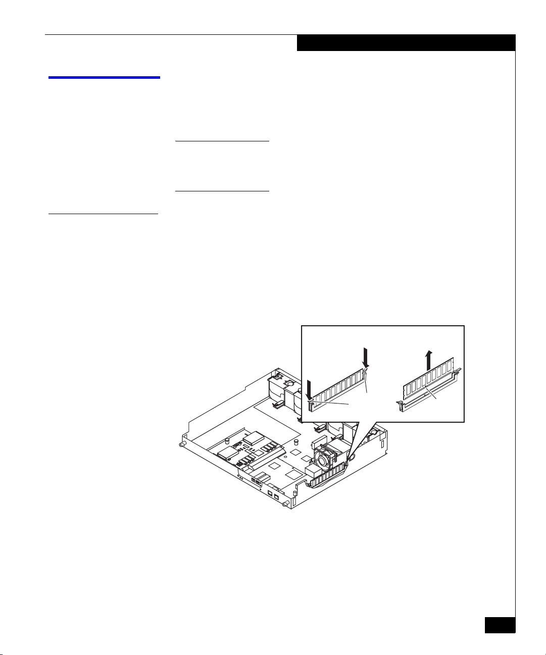
AX100-Series Replacing a Memory Card
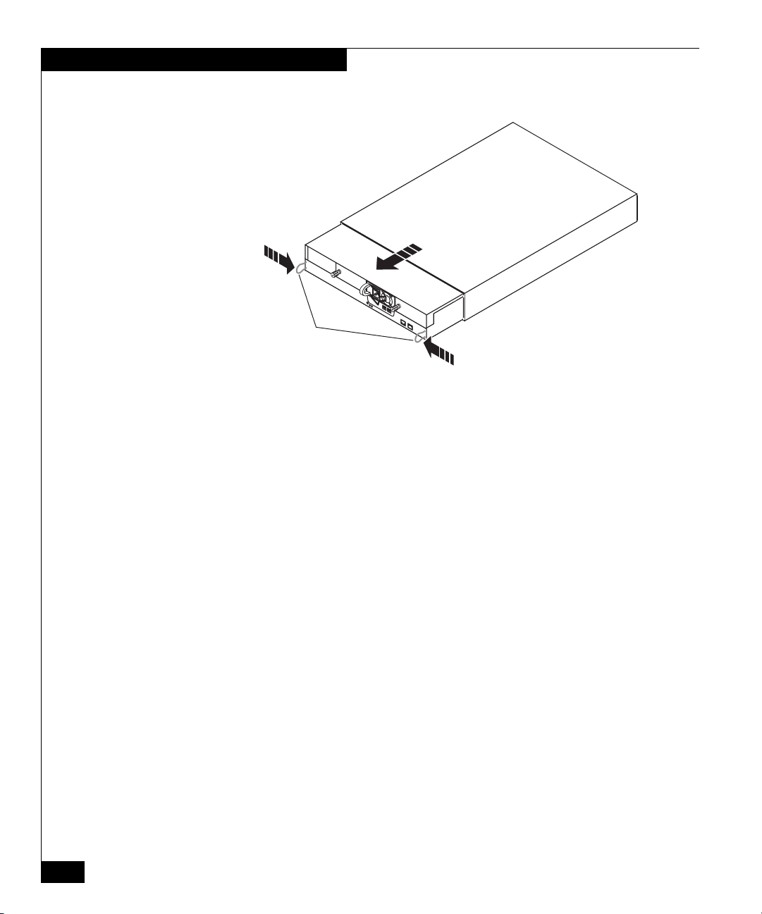
Handling FRUs
Handling FRUs
This section describes the precautions that you must take and the
general procedures you must follow when removing, installing, and
storing memory cards, the storage processor assembly, or any other
field replaceable unit (FRU).
Power Issues and
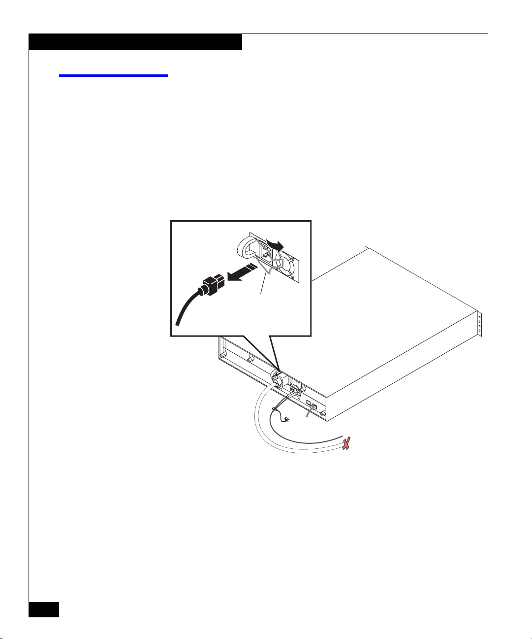
FRUs AX100-Series storage systems are designed to be powered up
continually. Disks and power supplies are hot repairable; that is, you
can replace faulty units while the system is running. Front bezels
should always be attached and each compartment should contain a
FRU or filler panel to ensure EMI compliance and proper air flow
over the FRUs.
You should not remove a faulty FRU until you have a replacement
available.
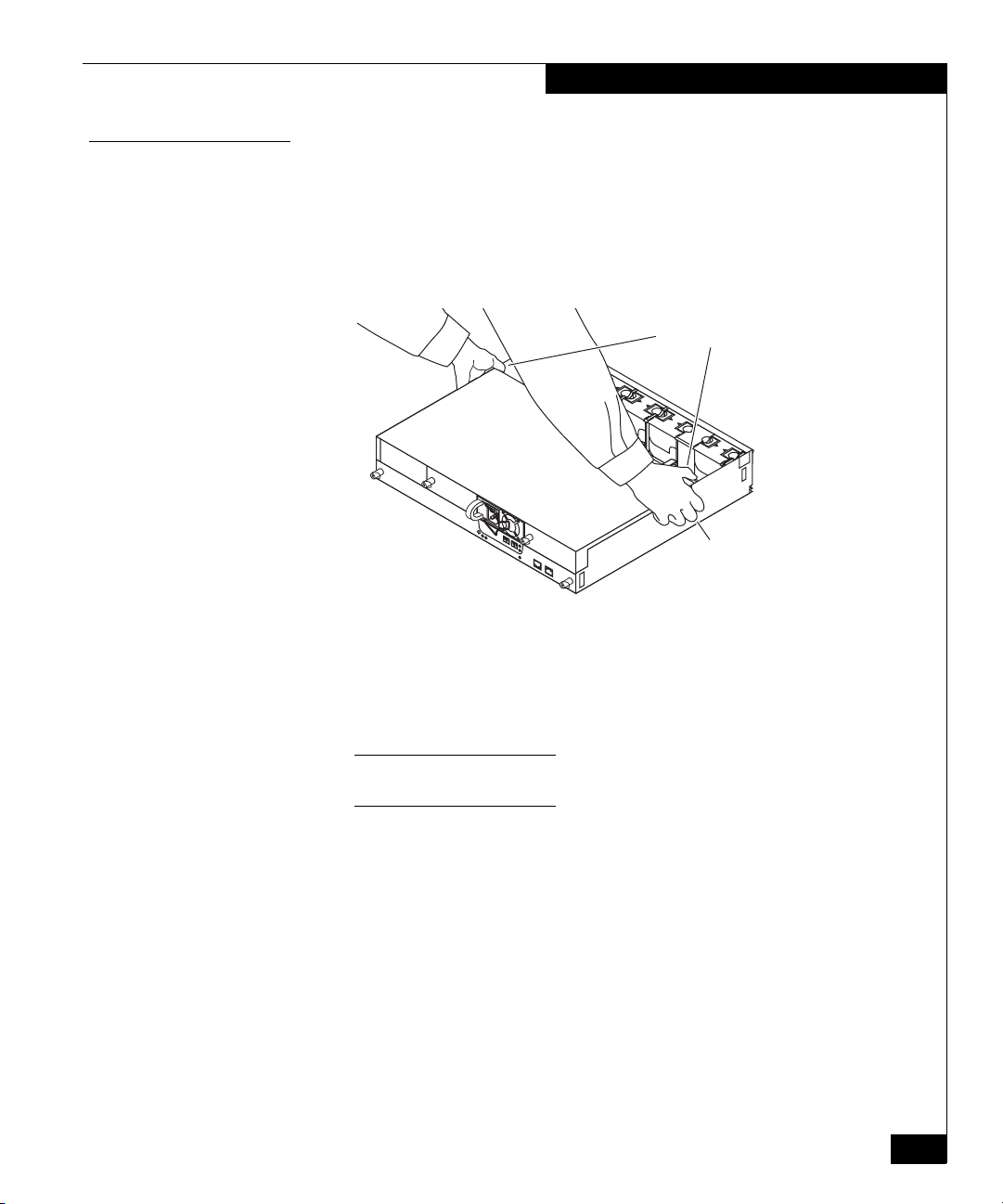
When you replace or install FRUs, you can inadvertently damage the
sensitive electronic circuits in the equipment by simply touching
them. Electrostatic charge that has accumulated on your body
discharges through the circuits. If the air in the work area is very dry,
running a humidifier in the work area will help decrease the risk of
ESD damage. You must follow the procedures below to prevent
damage to the equipment.
Read and understand the following instructions:
◆Provide enough room to work on the equipment. Clear the work
site of any unnecessary materials or materials that naturally build
up electrostatic charge, such as foam packaging, foam cups,
cellophane wrappers, and similar items.
◆Do not remove replacement or upgrade FRUs from their antistatic
packaging until you are ready to install them.
◆Before you service a storage system, gather together the ESD kit
and all other materials you will need. Once servicing begins,
avoid moving away from the work site; otherwise, you may build
up an electrostatic charge.
◆An ESD wristband is supplied with your storage system. To use
it, attach the clip of the ESD wristband (strap) to any bare
(unpainted) metal on the storage system; then put the wristband
around your wrist with the metal button against your skin.