EMC2 VNXe3100 User manual

This document describes how to upgrade the input/output (I/O) modules in a VNXe3100
or VNXe3150 dual-SP disk processor enclosure (DPE) to a different type of module.
Upgrading the I/O modules requires that both SPs have 8 GB of memory.
IMPORTANT
Your VNXe system must be running VNXe Operating System Environment 2.3 or later for
you to upgrade its I/O modules.
When you upgrade I/O modules, you must upgrade the I/O module in each SP.
Before you start
Before you begin the procedure:
◆Make sure you have the correct I/O modules for the upgrade. The
VNXe3100 Hardware
Information Guide
and the
VNX3150 Hardware Information Guide
on the VNXe
Support site (emc.com/vnxesupport) contains a list of supported I/O modules.
◆Refer to your EMC® VNXe™ online help (Servicing your system > Adding or replacing
faulted hardware components > Add a new hardware component) for instructions on
how to identify I/O modules and handle hardware components.
EMC® VNXe3100/VNXe3150
Upgrading the Input/Output Modules
P/N 300-014-237
REV 02

2 EMC VNXe3100/VNXe3150 — Upgrading Input/Output Modules
Tasks to upgrade I/O modules
You upgrade one I/O module in one SP at a time.
◆Task 1: Remove network settings .............................................................................. 2
◆Task 2: Preparing the storage processor (SP) for service ............................................ 4
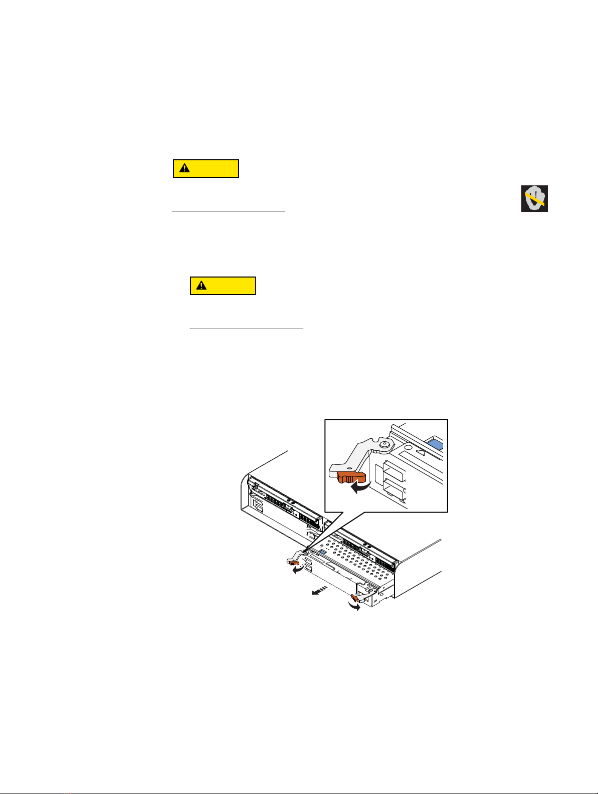
◆Task 3: Remove the SP assembly............................................................................... 5
◆Task 4: Remove the SP top cover ............................................................................... 6
◆Task 5: Remove the I/O module................................................................................. 7
◆Task 6: Install the new I/O module ............................................................................ 8
◆Task 7: Replace the SP top cover ............................................................................... 9
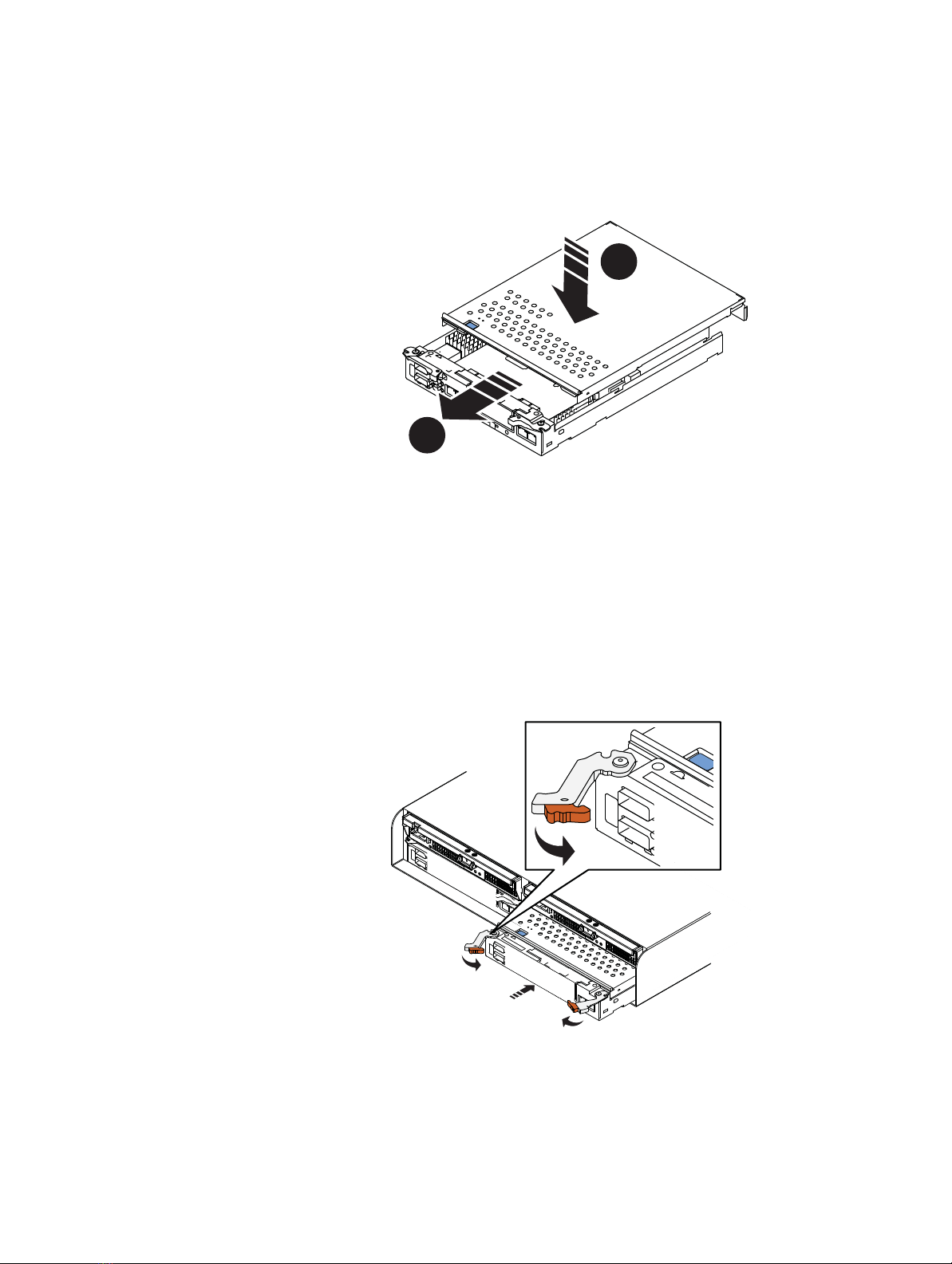
◆Task 8: Install the SP assembly ................................................................................. 9
◆Task 9: Reboot the storage processor ...................................................................... 10
◆Task 10: Verify that the the new I/O module is recognized....................................... 11
◆Task 11: Upgrade the I/O module to SP B................................................................ 11
◆Task 12: Commit the new I/O modules .................................................................... 11
◆Task 13: Verify the network interface settings for the new I/O modules.................... 12
◆Task 14: Verify the operation of the new I/O modules.............................................. 12
Task 1: Remove network settings
If you are upgrading a 1 GbE (4-port) I/O module to a 10 GbE (2-port) I/O module, you
must remove all network settings on eth12 and eth13 ports.
Removing the network settings for a Shared Folder Server
1. Alert users to stop I/O activity and/or stop I/O activity on the interfaces.
2. Open Unisphere and select Settings, then Shared Folder Server Settings.
3. In the Shared Folder Server Settings dialog box, select the Shared Folder Server.
4. For each I/O module that you are upgrading, if any network interfaces are assigned to
the ports for the I/O module that you are upgrading, do the following:
a. Record the network settings for the interface:
–IPaddress
–Subnetmask
– Default gateway
–Portnumber
b. Click Details, and select the network interface.
c. Either remove the interface or move the interfaces to a new port:
Note: If only one interface is available, you cannot remove it. Instead, you must
move the interface to a new port.
To remove the interface:
Click Remove Interface.

Tasks to upgrade I/O modules
EMC VNXe3100/VNXe3150 — Upgrading Input/Output Modules 3
To move the interface to a new port:
– Click Modify.
–IntheModify network interface dialog box, click Show advanced.
– From the drop-down list, select a new Ethernet port other than eth12 or eth13
for the interface.
– Click Update.
– When the message Network interface was modified successfully
appears, click Close to close the Modify network interface dialog box.
Removing the network settings for an iSCSI Server
1. Alert users to stop I/O activity and/or stop I/O activity on the interfaces.
2. Open Unisphere and select Settings, then iSCSI Server Settings.
3. In the iSCSI Server Settings dialog box, select the iSCSI Server.
4. For each I/O module that you are upgrading, if any network interfaces are assigned to
the ports for the I/O module that you are upgrading, do the following:
a. Record the network settings for the interface:
–IPaddress
–Subnetmask
– Default gateway
–Portnumber
b. Click Details, and select the network interface.
c. Either remove the interface or move the interfaces to a new port:
Note: If only one interface is available, you cannot remove it. Instead, you must
move the interface to a new port.
To remove the interface:
Click Remove Interface.
To move the interface to a new port:
– Click Modify.
–IntheModify network interface dialog box, click Show advanced.
– From the drop-down list, select a new Ethernet port other than eth12 or eth13
for the interface.
– Click Update.
– When the message Network interface was modified successfully
appears, click Close to close the Modify network interface dialog box.

4 EMC VNXe3100/VNXe3150 — Upgrading Input/Output Modules
Tasks to upgrade I/O modules
Task 2: Preparing the storage processor (SP) for service
IMPORTANT
To protect your VNXe system from accidental data loss while you upgrade an I/O module in
an SP, you must prepare the SP for service before you upgrade any of its I/O modules. You
prepare the SP for service by putting it in Service mode. Both SPs must not be in Service
mode at the same time.
1. Open Unisphere™ and select Settings, then Service System.
2. Log in with your service password.
3. In the System Components column, select the storage processor (SP A or SP B).
4. Under Service Actions, select Enter Service Mode, then Execute service action.
5. In the Service Confirmation dialog box click OK.
Putting an SP into Service mode takes about 10 minutes. The storage processor fault
LED will flash alternating amber and blue while the SP remains in Service mode and is
receiving active power.
6. Wait until the SP fault LED is flashing alternating amber and blue before continuing to
the next task.
1
1 GBE
01
X4
6Gb SAS
6Gb SAS
23
1
0
e3e0 e1 e2
1 GbE
SP fault

Tasks to upgrade I/O modules
EMC VNXe3100/VNXe3150 — Upgrading Input/Output Modules 5
Task 3: Remove the SP assembly
The I/O module resides on the SP printed circuit board (CPU board). To upgrade an I/O
module, you must remove the SP assembly from the chassis, and then remove its cover to
gain access to processor board components.
Follow these steps to remove the SP assembly:
DO NOT REMOVE an SP assembly while the “Unsafe to remove SP” LED is on. The
light indicates that you may interrupt a vital system or data-caching process.
1. Disconnect the network and all other cables from the back of the assembly that will
include the new I/O module.
Do not remove
any cables from the other SP assembly.
Mark the cables with the port numbers from which you removed them.
The SP assembly comes completely out of the chassis. In addition to holding the
latches, be prepared to support the SP assembly to avoid dropping it.
2. Locate the left and right latches.
3. Pinch the orange tabs and pull the latches to the sides to eject the SP assembly from
the chassis.
4. Pull the SP assembly straight out of the chassis and place it on a static-free surface.
CL4682

6 EMC VNXe3100/VNXe3150 — Upgrading Input/Output Modules
Tasks to upgrade I/O modules
Task 4: Remove the SP top cover
1. Press the blue button on the cover.
2. Push the cover straight back 1/4 inch.
3. Lift the cover up.
2
3
1
CL4683

Tasks to upgrade I/O modules
EMC VNXe3100/VNXe3150 — Upgrading Input/Output Modules 7
Task 5: Remove the I/O module
1. Lift the blue latch carefully until it ejects the I/O module from the connector.
2. Lift the module out and away from the canister and place it on a static free surface.
21
CL4688

8 EMC VNXe3100/VNXe3150 — Upgrading Input/Output Modules
Tasks to upgrade I/O modules
Task 6: Install the new I/O module
1. Unpack one new I/O module.
2. Angle the I/O module slightly so it fits into the canister and align it with the blue
alignment pins.
Do not attempt to seat the I/O module into the CPU connector while you are holding
the I/O module at an angle. Doing so will damage the connections. The I/O module
should be flat before you attempt to seat the connector.
3. With the module aligned and parallel to the CPU board, press the latch down to fully
seat the module in the connector.
4. Push down on the force point indicated on the I/O module to ensure that the module
is completely seated on the processor board.
IMPORTANT
The system may not recognize the new I/O module, and report it as “unsupported” or
“unknown” until you manually reboot the storage processor. See
Task 9: Reboot the
storage processor
on page 10.
2
3
1
CL4689

Tasks to upgrade I/O modules
EMC VNXe3100/VNXe3150 — Upgrading Input/Output Modules 9
Task 7: Replace the SP top cover
1. Align the cover tabs with the notches in the canister.
2. Slide it forward 1/4 inch until the tab secures the cover.
Task 8: Install the SP assembly
1. Pull out the latches on each side of the SP assembly and make sure they stay in the
open position.
2. Align the SP assembly with the chassis opening and push it straight into the chassis.
The latches begin to close when they contact the chassis edges.
3. Close the right and left latches to fully seat the SP assembly in the chassis.
An audible click indicates that the latches are secure.
The SP begins powering up immediately after connection to an active AC power
source.
2
1
CL4686
CL4687

10 EMC VNXe3100/VNXe3150 — Upgrading Input/Output Modules
Tasks to upgrade I/O modules
IMPORTANT
If you installed a 10 GbE (2-port) I/O module and the SP Fault light stays on solid
amber and does not start flashing, do the following:
a. Pinch the orange tabs and pull the latches to the sides to eject the SP assembly
from the chassis.
b. Pull the SP assembly two inches out of the chassis.
c. Push the SP assembly back into the chassis.
d. Close the right and left latches to fully seat the SP assembly in the chassis.
An audible click indicates that the latches are secure.
After a few seconds the SP Fault light should start flashing.
4. On the back of the SP assembly, connect cables to the new I/O module:
a. Connect a network cable to each port on the new I/O module that you want to use.
b. Reconnect any cables, other than the network cables connected to the old I/O
module ports, that you removed from the storage processor, being sure to connect
these cables to the same ports from which you removed them.
Task 9: Reboot the storage processor
Once you have upgraded the I/O module and returned the SP assembly to the chassis,
reboot the recently upgraded SP to ensure that it returns to normal mode:
1. From Unisphere, select Settings, then Service System.
2. Log in with your service password.
3. In the System Components column, select the serviced storage processor (SP A).
4. Under Service Actions, select Reboot, then Execute service action.
5. In the Service Confirmation dialog box, click OK.
It may take several minutes for the system to complete its reboot and return to normal
mode.
6. Refresh your browser, or follow the on-screen instructions, to bring the software out of
service mode and restore full-function Unisphere.

Tasks to upgrade I/O modules
EMC VNXe3100/VNXe3150 — Upgrading Input/Output Modules 11
Task 10: Verify that the the new I/O module is recognized
Verify that the new I/O module is recognized by your system, and not faulted:
1. Open Unisphere™ and select System, then System Health.
2. Select the SP in the System Components list or the graphical view:
• In the System Components list, the new module should be marked with a yellow
Warning status icon because it has not been committed yet.
• In the graphical view, the module should be highlighted yellow.
If the system health monitor shows the module as faulted, contact your service
provider.
Task 11: Upgrade the I/O module to SP B
IMPORTANT
You must
upgrade I/O modules in pairs:
SP B must match the configuration and content of
SP A.
You have completed the upgrade of the I/O module in SP A. Now you are ready to upgrade
the I/O module in SP B by repeating the following tasks that you just performed for SP A:
1.
Task 2: Preparing the storage processor (SP) for service
on page 4
2.
Task 3: Remove the SP assembly
on page 5
3.
Task 4: Remove the SP top cover
on page 6
4.
Task 5: Remove the I/O module
on page 7
5.
Task 6: Install the new I/O module
on page 8
6.
Task 7: Replace the SP top cover
on page 9
7.
Task 8: Install the SP assembly
on page 9
8.
Task 9: Reboot the storage processor
on page 10
9.
Task 10: Verify that the the new I/O module is recognized
on page 11
Task 12: Commit the new I/O modules
You must commit the new I/O modules before they can be used.
1. In Unisphere, select System, then System Health.
2. Select the DPE in the System Components list.
3. In the Component Description window, click Commit I/O Modules.

12 EMC VNXe3100/VNXe3150 — Upgrading Input/Output Modules
Tasks to upgrade I/O modules
Task 13: Verify the network interface settings for the new I/O modules
If you had interfaces on eth12 and eth13 for the old I/O modules, use the procedures
below to verify that the new I/O modules have the same settings that the old I/O modules
had for eth12 and eth13.
Note: You should have recorded these settings in Task 1.
Verifying network interface settings for a Shared Folder
Server
1. In Unisphere and select Settings.
2. Select Shared Folder Server Settings.
3. In the Shared Folder Server Settings dialog box, verify the network settings for the
ports on the new I/O modules.
These settings should agree with IP address, subnet mask, and default gateway
information that you recorded in Task 1. If the IP address and the Port number are Not
configured, go to the
Troubleshooting
on page 13.
Verifying network interface settings for an iSCSI Server
1. In Unisphere and select Settings.
2. Select iSCSI Server Settings.
3. In the iSCSI Server Settings dialog box, verify the network settings for the ports on the
new I/O modules.
These settings should agree with IP address, subnet mask, and default gateway
information that you recorded in Task 1. If the IP address and the Port number are Not
configured, go to the
Troubleshooting
on page 13.
Task 14: Verify the operation of the new I/O modules
Verify that the new I/O module on each SP is recognized by your system, and operating
correctly:
1. In Unisphere, select System, then System Health.
1. Select the SP in the System Components list or the graphical view:
• In the System Components list, the new module should be marked with a status
OK icon:
• In the graphical view, the module should be highlighted green.
If the system health monitor shows the new module as faulted, contact your service
provider.

Troubleshooting
EMC VNXe3100/VNXe3150 — Upgrading Input/Output Modules 13
Troubleshooting
If any network settings on the third and fourth ports of the old I/O modules were not
removed prior to the I/O module upgrade, these settings are visible in Unisphere. Also, in
the Shared Folder Server Settings and/or iSCSI Server Settings dialog box, the IP address
is Not configured for these ports. These network settings cannot be reused or
removed after the upgrade. To fix this situation, follow this procedure:
1. Log into Unisphere™ and select Settings, then Service System.
2. Log in with your service password.
3. In the System Components column, select Storage System.
4. Under Service Actions, select Enable SSH, then Execute service action.
5. In the confirmation dialog box, click OK to enable SSH.
6. Download an SSH client, such as PuTTY, to a computer that has network access to the
system.
You may need to install the SSH client before you can launch it.
7. Launch the SSH client.
8. In the SSH client, use the management IP address to connect to the VNXe system.
For example, in PuTTY, type the management IP for the destination.
9. Log in as the Service user, then type the password for the Service account to log in to
the system.
10. Use the svc_change_config command with the --cleanup_network option to remove
the network settings on any non-existent ports.
For example:
service@vnxe126 spa:~> svc_change_config --cleanup_network
Found the following network interfaces on non-existent ports.
Found invalid entry: linux_dev=eth13 protocol=IP device=fsn13
local=10.6.6.6 netmask=255.255.255.0 broadcast=10.6.6.6 mtu=1500
vlan=0
Found invalid entry: linux_dev=eth12 protocol=IP device=fsn12
local=10.6.8.127 netmask=255.255.255.0 broadcast=10.6.6.6 mtu=1500
vlan=0
Removing these interfaces requires restarting the management
services on the SP.
Are you sure you want to proceed <y/N>: y
Removing network interfaces on non-existent ports.
Restarting management services.
Management services have been restarted. Please wait a few minutes
before opening a Unisphere session.
11. After a few minutes, open Unisphere again and recreate the interface(s) for each port
for the new I/O modules:
a. Open Unisphere and select Settings.
b. Select either Shared Folder Server Settings or iSCSI Server Settings.
c. In the Shared Folder Server Settings or iSCSI Server Settings dialog box, click Add
Network Interface.

14 EMC VNXe3100/VNXe3150 — Upgrading Input/Output Modules
Troubleshooting
d. Enter the network settings that you recorded earlier for the interface:
–IPaddress
–Subnetmask
– Default gateway
–Portnumber
e. Click Apply Changes.
12. Continue the upgrade procedure starting with
Task 13: Verify the network interface
settings for the new I/O modules
on page 12.
Copyright © 2011-2012 EMC Corporation. All rights reserved. Published in the USA.
Published September, 2012
EMC believes the information in this publication is accurate as of its publication date. The information is subject to change without
notice.
The information in this publication is provided as is. EMC Corporation makes no representations or warranties of any
kind with respect to the information in this publication, and specifically disclaims implied warranties of
merchantability or fitness for a particular purpose. Use, copying, and distribution of any EMC software described in this
publication requires an applicable software license.
EMC2, EMC, and the EMC logo are registered trademarks or trademarks of EMC Corporation in the United States and other countries.
All other trademarks used herein are the property of their respective owners.
For the most up-to-date regulatory document for your product line, go to the technical documentation and advisories
section on EMC Online Support.
Other manuals for VNXe3100
4
This manual suits for next models
1
Table of contents
Popular Control Unit manuals by other brands

Feig Electronic
Feig Electronic OBID i-scan ID ISC.LR2500-A installation manual

Ambu
Ambu PEEP 10 Instructions for use

aci
aci EX2432D Installation & operation instructions

AT&T
AT&T DEFINITY 7500 series user manual

Wabtec
Wabtec VX Operation & maintenance instructions

Digikeijs
Digikeijs DR5013 DIGIREVERSE instruction manual