EMC2 SVR-D1U-R610 Parts list manual

1
This document describes installation and replacement procedures for
the SVR-D1U-R610 server. Topics include:
◆Technical information and requirements .......................................... 2
◆Installing the server in a rack or cabinet ........................................... 4
◆Replacing the server drives............................................................... 12
◆Replacing a server power supply..................................................... 15
◆Replacing the server chassis ............................................................. 17
◆Removing mounting rails from the cabinet.................................... 26
◆Adjusting universal rail length......................................................... 27
Note: Replacement of server components, including disk drives, power
supplies, or chassis, by unauthorized personnel may void service warranties.
Review your Service Contract for clarification before attempting to perform
hardware service procedures.
SVR-D1U-R610
Installation and Replacement Guide
P/N 300-009-319
Rev A03
September 28, 2010

2SVR-D1U-R610 Installation and Replacement Guide
Technical information and requirements
Device power, cooling, and weight information
Device dimensions
Device placement requirements
There are no restrictions on the location of the server in the cabinet
(rack). Allow at least 30 inches of service clearance in front of the
cabinet. Power distribution must support the number of outlets
required for the server and the server power rating listed in the
“Device power, cooling, and weight information.” For additional
information, refer to the preparation/planning guides for your
specific site and cabinet.
Requirement Description
AC line voltage 90 - 264 V AC, autoranging, 47- 63 Hz
Wattage 502 W (Energy Smart)
Heat dissipation 1712.9 BTU/hr maximum (Energy Smart)
Maximum inrush current Under typical line conditions and over the entire
system ambient operating range, the in-rush
current may reach 55 A per power supply for
10 ms or less.
Maximum weight 39 lb (17.69 kg)
Dimension Server Server with rails
Height 1.68 in (4.26 cm) 1.0 U (with or without
bezel)
Depth 30.39 in (77.2 cm) Adjustable
Width 17.4 in (44.31 cm)
without rack latches
48.24 cm (18.99 in) with
rack latches

3
Technical information and requirements
SVR-D1U-R610 Installation and Replacement Guide
Operating limits
The ambient temperature specification is measured at the front bezel
inlet. The site must have air conditioning of the correct size and
placement to maintain the specified ambient temperature range and
offset the heat dissipation listed on page 2.
Shipping and storage requirements
Requirement Description
Ambient temperature 10oC to 35oC (50oF to 95oF)
Temperature gradient 10oC/hr (18oF/hr)
Relative humidity
extremes
20% to 80% noncondensing
Recommended operating
relative humidity
40% to 55% noncondensing
Elevation -50 to 10,000 ft (-16 to 3,048 m)a
a. For altitudes above 2,950 feet, the maximum operating temperature is
de-rated 1°F/550 ft.
Requirement Description
Ambient temperature -40oC to 65oC (-40oF to 149oF)
Temperature gradient 25oC/hr (45oF/hr)
Relative humidity 10% to 90% noncondensing
Elevation -50 to 35,000 ft (-16 to 10,600 m)

4SVR-D1U-R610 Installation and Replacement Guide
Installing the server in a rack or cabinet
This section describes how to install the SVR-D1U-R610 server. It is
divided into the following sections:
◆“Mounting kit parts” on page 4
◆“Removing inner rails from the universal rail kits” on page 5
◆“Attaching the inner rails” on page 5
◆“Installing the universal rails in the cabinet” on page 6
◆“Installing the server in the cabinet” on page 7
◆“Installing bezels” on page 10
Mounting kit parts
The server mounting kit includes rails, hardware, and bezel as listed
in the following table.
You will need a # 2 Phillips-head screwdriver to complete the
installation of the rails and server.
Component Use
2 adjustable universal slide rails Attach front to back on either side
between NEMA channels
Two Phillips M5 18 mm screws Stabilize the rail mounting
1 U bezel (front rack panel) One per server — application specific
(includes inner rails for
connection to server)

5
Installing the server in a rack or cabinet
SVR-D1U-R610 Installation and Replacement Guide
Removing inner rails from the universal rail kits
Figure 1 shows how to remove the inner rail from each rail assembly.
1. Pull the blue inner rail release button, and extend the inner rail to
the lock position.
2. Slide the white disconnect tab forward to release the inner rail
from rest of the assembly, and then remove the rail.
Figure 1 Removing inner rails from the rail assembly
Attaching the inner rails
Figure 2 shows how to attach inner rails to each side of the server.
1. Align the protruding rail notches with the connection studs on
the server.
2. Push the rail along the server until the studs fit securely into the
notches; an audible click indicates that the rail is secure.
Figure 2 Attaching inner rails
CL4346
Click!
CL4347a

6SVR-D1U-R610 Installation and Replacement Guide
Installing the server in a rack or cabinet
Installing the universal rails in the cabinet
Note: By default, the universal rail kits support cabinets in which the front
and rear mounting channels are 24 inches to 29 inches apart (type “A” rails)
or 21 to 25 inches apart (type “B” rails). If the mounting channels in your
cabinet are not within the default range, refer to “Adjusting universal rail
length” on page 27.
To avoid potential damage to the front connection mechanism, make sure to
attach the rails to the rear channels first (step 1 below).
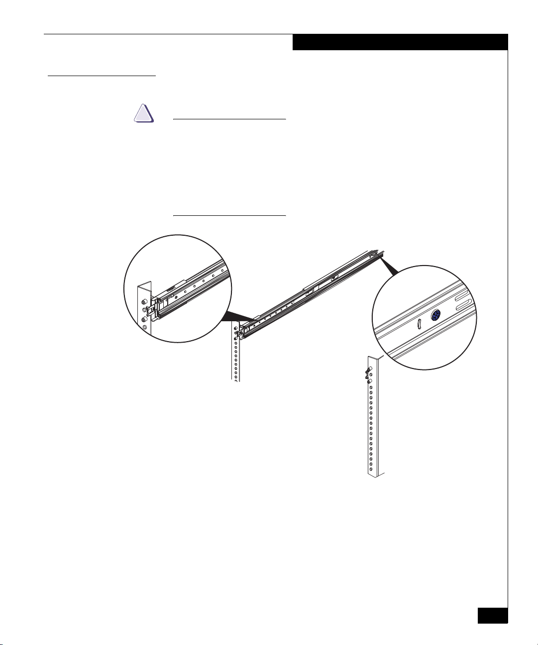
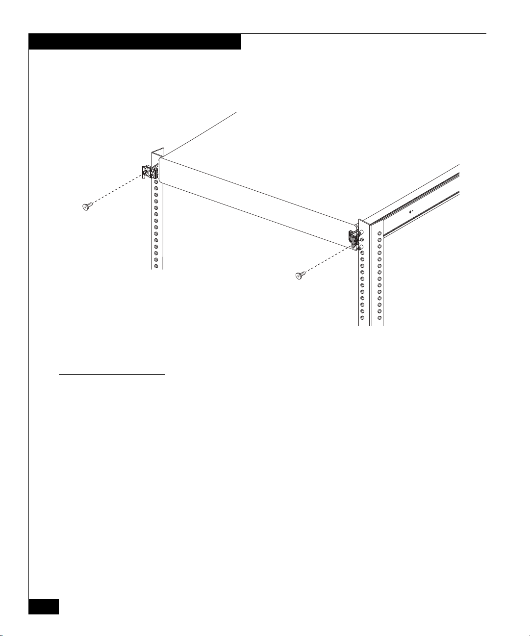
Figure 3 describes how to mount each rail in the cabinet:
Pull the middle rail out and into the locked position. Use the exposed
middle rail for leverage as you attach the assembly to the cabinet
channels.
1. From the front of the cabinet, position the alignment pins and
release bracket over the rear cabinet mounting channel. Insert the
alignment pins on the rail assembly into the rear channel holes for
the selected 1 U (1.75 in.) of cabinet space. Push the assembly
backwards onto the channel; an audible click indicates that the
connection is secure.
2. Pull the front alignment pins into position securely in the
cabinet’s front channel. An audible click indicates that the rail is
firmly attached to the channel.
Note:Figure 3 shows the right
rail, from the front, with the
cabinet sides removed for
clarity.
Figure 3 Installing universal rails
1
2
Click!
Click!
CL4348

7
Installing the server in a rack or cabinet
SVR-D1U-R610 Installation and Replacement Guide
Installing the server in the cabinet
CAUTION
!
The enclosure is heavy and should be installed into a rack by two
people. To avoid personal injury and/or damage to the equipment,
do not attempt to lift and install the enclosure into a rack without a
mechanical lift and/or help from another person.
Before mounting the server to the rails, make sure the ball bearing
retainer sheath is locked forward, and the secondary security
plungers are in the default (down and locked) position.
Figure 4 Location of the retainer sheath and secondary security plunger
Figure 5, Figure 6, and Figure 7 show how to install the server in the
rackmount cabinet:
1. From the front of the cabinet, align the inner rails attached to the
server with the mounting channels on the slide rails.
2. Slide the server halfway into the slide rails.
CL4349b

10 SVR-D1U-R610 Installation and Replacement Guide
Installing the server in a rack or cabinet
4. To further secure the rail assembly in the cabinet, insert and
tighten a stabilizer screw directly behind each bezel latch.
Figure 7 Installing the stabilizer screws
Installing bezels
Figure 8 shows how to install a front bezel:
1. Press the bezel onto the latch brackets until it snaps into place.
CL4536

12 SVR-D1U-R610 Installation and Replacement Guide
Replacing the server drives
This section describes replacing a failed drive. Replacing the drive
consists of the following steps:
◆Identifying the failed drive
◆Replacing the failed drive
Note: Replacement of server components, including disk drives, power
supplies, or chassis, by unauthorized personnel may void service warranties.
Review your Service Contract for clarification before attempting to perform
hardware service procedures.
All drives are installed at the front of the server and connect to the
system board through the SAS backplane. Hard drives are supplied
in special hot-swappable hard-drive carriers that fit in the hard-drive
bays.
Use only drives that have been tested and approved for use with the
SAS backplane board.
CAUTION
!
To maintain proper system cooling, all hard-drive bays must have
drives or blanks installed.
Do not turn off or reboot your system while the drive is being
formatted. Doing so can cause a drive failure.
Use appropriate ESD precautions, including the use of a grounding
strap, when performing the drive replacement procedure.
Identifying the failed drive
Before you can replace the failed drive, you must identify which
drive has failed.
Remove the front bezel, if present in your configuration. See Figure 9.
Note: Bezels are application-specific, and may not appear as shown. All
bezels include a key entry. Most include two tabs at either side that you press
toward the center to release the bezel from its latches.

13
Replacing the server drives
SVR-D1U-R610 Installation and Replacement Guide
Figure 9 Removing a front bezel
Each drive sled has LED indicators that show the current status of the
drive. A failed drive will have an amber LED indicator.
Replacing the failed drive
Once you have identified the failed drive:
1. Press the release button, and then open the drive handle and pull
the failed hard drive from the server chassis. See Figure 10.
CL4538

14 SVR-D1U-R610 Installation and Replacement Guide
Replacing the server drives
Figure 10 Removing and replacing a drive
CAUTION
!
When installing a hard drive, ensure that the adjacent drives are
fully installed. Inserting a hard-drive carrier and attempting to lock
its handle next to a partially installed carrier can damage the
partially installed carrier's shield spring and make it unusable.
2. Install the hard drive. See Figure 10:
a. Press the button on the front of the drive carrier and open the
handle.
b. Insert the hard-drive carrier into the drive bay until the carrier
contacts the backplane.
c. Close the handle to lock the drive in place.
Once you have installed the replacement drive, you must add
the drive to the drive configuration through the service menu.
3. Replace the front bezel.
The drive replacement procedure is complete.

15
Replacing a server power supply
SVR-D1U-R610 Installation and Replacement Guide
Replacing a server power supply
Note: Replacement of server components, including disk drives, power
supplies, or chassis, by unauthorized personnel may void service warranties.
Review your Service Contract for clarification before attempting to perform
hardware service procedures.
The server is powered by redundant, hot-swappable power supplies
located in the back of the unit. Once you have identified the failed
power supply, you can easily replace it and return the system to
normal operation.
This section describes how to replace a failed power supply.
Replacing a server power supply consists of the following steps:
◆Identifying the failed power supply
◆Removing and replacing the power supply
Note: The power supplies are “hot-swappable” and can be replaced during
normal system operation.
CAUTION
!
Use appropriate ESD precautions, including the use of a grounding
strap, when performing the power supply replacement procedure.
Identifying the failed power supply
You must visually verify the power supply that has failed before you
try to replace it. The server power supplies have LED indicators that
turn amber when the power supply has failed.
Removing the power supply
To remove and replace a power supply:
1. Disconnect the power cable from the power source and the power
supply you intend to remove and remove the cables from the
Velcro s trap.
2. Press the lever release latch and slide the power supply out of the
chassis. See Figure 11.

16 SVR-D1U-R610 Installation and Replacement Guide
Replacing a server power supply
Figure 11 Removing and replacing a power supply
CAUTION
!
The power supply may be hot. Use caution when removing the
failed power supply.
Replacing a power supply
To replace a power supply:
1. On a system with redundant power supplies, verify that both
power supplies are the same type and have the same maximum
output power.
Note: The maximum output power (shown in watts) is listed on the
power supply label.
2. Slide the new power supply into the chassis until the power
supply is fully seated and the release latch snaps into place. See
Figure 11.
3. Connect the power cable to the power supply and plug the cable
into a power outlet.
When connecting the power cable, secure the cable with the
Velcro s trap.
Note: When installing a new power supply, allow several seconds for the
system to recognize the power supply and determine its status. The
power-supply status indicator turns green to signify that the power supply is
functioning properly.
The power supply replacement procedure is complete.

17
Replacing the server chassis
SVR-D1U-R610 Installation and Replacement Guide
Replacing the server chassis
Note: Replacement of server components, including disk drives, power
supplies, or chassis, by unauthorized personnel may void service warranties.
Review your Service Contract for clarification before attempting to perform
hardware service procedures.
Several items within the server chassis are not replaceable as
individual FRUs:
◆Motherboard
◆Mid-plane assembly
◆DVD-ROM
◆Server HBA
If any of these components fail, you must replace the entire server.
The replacement procedure is divided into the following sections:
◆“Powering down the server” on page 17
◆“Removing the server from the cabinet” on page 17
◆“Installing a replacement server” on page 24
◆“Removing inner rails from the original server” on page 24
◆“Attaching the slide rails” on page 24
◆“Installing the new server in the cabinet” on page 25
◆“Installing the bezel” on page 25
Powering down the server
You must power down the server before you pull the server from the
rack and install a replacement.
Removing the server from the cabinet
To remove the server from the cabinet:
1. Remove all power, Ethernet, and Fibre Channel cables from the
back of the server. Label the cables so they can be easily identified
when they are connected to the replacement server.

18 SVR-D1U-R610 Installation and Replacement Guide
Replacing the server chassis
2. Remove the bezel as shown in Figure 12.
Figure 12 Removing a front bezel
Note: Bezels are application-specific, and may not appear as shown. All
bezels include a key entry. Most include two tabs at either side that you press
toward the center to release the bezel from its latches.
CL4538
Table of contents
Other EMC2 Server manuals
Popular Server manuals by other brands

Vxl
Vxl Itona F Series Hardware installation guide

HMS
HMS Intesis INMBSMIT050C000 user manual

TANDBERG
TANDBERG Video Communication Server Administrator's guide

Lenovo
Lenovo ThinkSystem ST250 V3 System configuration guide

Commell
Commell CMB-172 User manual and installation guide

Sun Microsystems
Sun Microsystems Sun Fire X4100 M2 installation guide