Emcore i65M3 User manual
- 1 -
4041650300110PCopyright®2012 All Rights Reserved.
Quick Installation Guide
Version 1.1
If you have any technical difculties, please consult the user’s manual rst at:
ftp://ftp.arbor.com.tw/pub/manual
Please do not hesitate to call or e-mail our customer service when you still can not
nd out the answer.
http://www.arbor.com.tw
E-mail: info@arbor.com.tw
♦ Technical Support
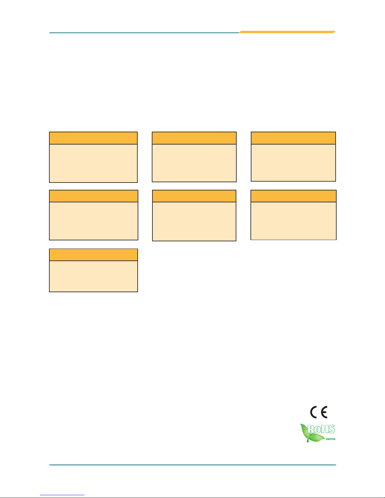
EmCORE-i65M3
3.5" Compact Board
I/O
CFast/ SATA/ USB/ COM/
Mini-card/ LPC
Video
Dual Channels 24-bit
LVDS/ DVI
-I
LAN
2 x Intel
®
82583V PCIe
Gigabit Ethernet
Audio
Realtek ALC662 HD Audio
CODEC, Line-in/ Line-out/
Mic-in
Form Factor
3.5"Compact Board
CPU
Intel®CeleronTM 827E
Processor
Chipset
Intel®PCH HM65
FCC Class A
This device complies with Part 15 of the FCC Rules. Operation is subject to the
following two conditions : (1) this device may not cause harmful interference, and
(2) this device must accept any interference received, including interference that
may cause undesired operation.
- 2 -
Ordering Information
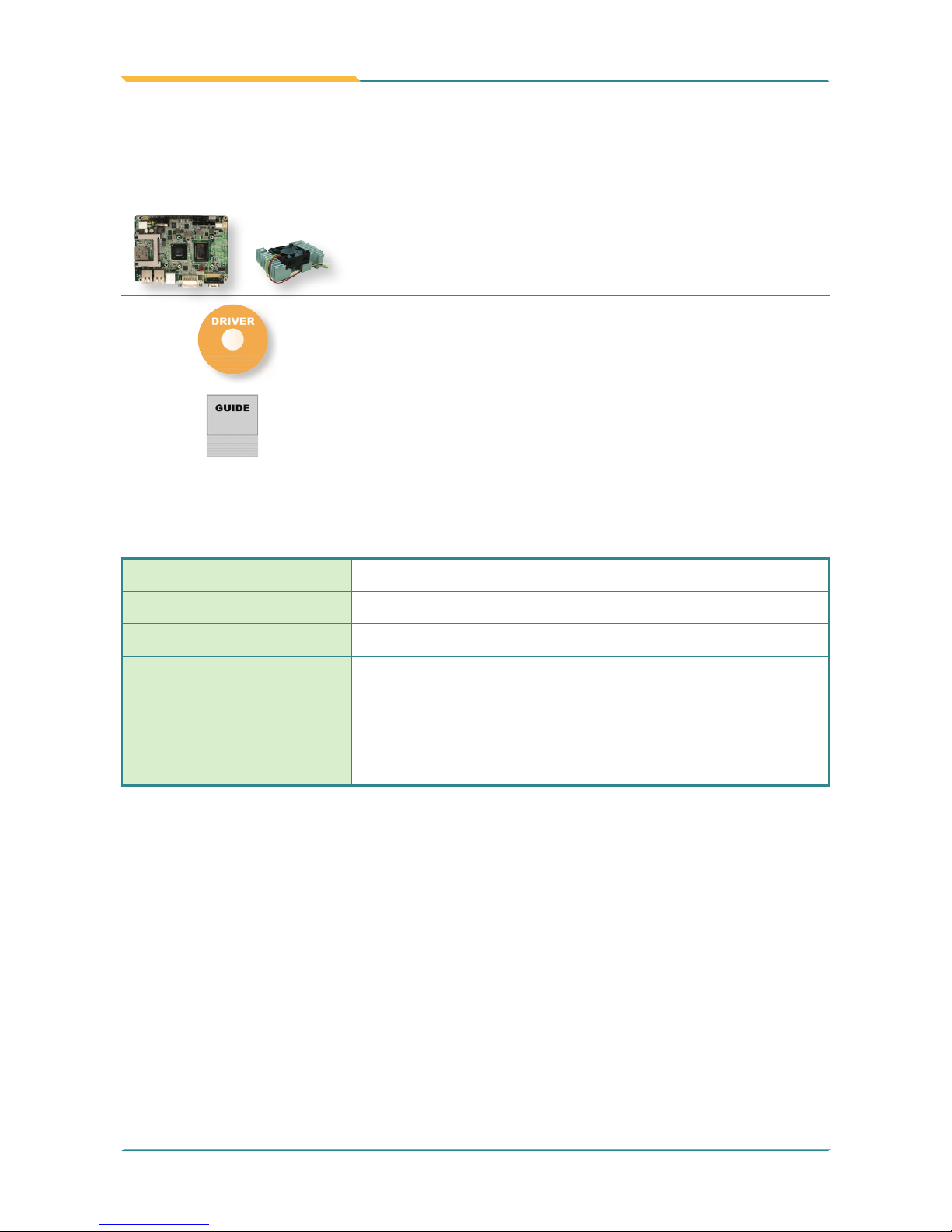
Packing List
EmCORE-i65M3-827E Intel® CeleronTM 827E 3.5" Compact Board
FCDB-1293 4 x COM ports, 8-bit digital I/O daughterboard
FCDB-349R 16-bit Digital I/O board
CBK-06-65M3-00
Cable kit
2 x SATA cables
2 x USB dual port cables
1 x Audio Cable
1 x COM port cable
Before you begin installing your Compact Board, please make sure that the following
materials have been shipped:
1 x EmCORE-i65M3 3.5" Compact Board with heatsink
1 x Driver CD
1 x Quick Installation Guide
If any of the above items is damaged or missing, contact your vendor immediately.

- 3 -
The Installation Paths of CD Driver
Windows XP
Driver Path
CHIPSET \CHIPSET
VGA \GRAPHICS\WinXP
AUDIO \AUDIO\WinXP_ALC662
LAN \ETHERNET\WinXP_82583V
Framework \NET Framework
Windows 7
Driver Path
CHIPSET \CHIPSET
VGA \GRAPHICS\Win7
AUDIO \AUDIO\Win7_ALC662
LAN \ETHERNET\Win7_82583V
Intel Turbo \CPU_utility

- 4 -
Board Dimensions
Unit: mm

- 5 -
Form Factor 3.5" Compact Board
CPU Soldered onboard Intel® Sandy Bridge Celeron™ 827E
1.4GHz processor
Chipset Intel® PCH HM65
System Memory 1 x 204-pin DDR3 SO-DIMM socket supporting 1066/800MHz
SDRAM up to 4GB
Graphics Integrated Intel® HD Graphics 3000 supporting 24-bit dual
channels LVDS and DVI-I
Ethernet 2 x Intel® 82583V PCIe Gigabit Ethernet controllers
I/O Chips Fintek F71869ED
BIOS AMI PnP Flash BIOS
Audio Realtek ALC662 5.1 Channel HD Audio CODEC, Mic-in/ Line-in/
Line-out
Storage
2 x Serial ATA ports with 600MB/s HDD transfer rate
1 x CFast socket
Serial Port
2 x COM ports (COM1: RS-232, COM2: RS-232/422/485
selectable, RS-485 auto ow control)
Extra 4 x COM ports via FCDB-1293
Keyboard & Mouse USB interface for Keyboard and Mouse
Universal Serial Bus 6 x USB 2.0 ports
Digital IO 16-bit programmable Digital Input/Output via FCDB-349R
Expansion Bus
1 x Mini-card socket
1 x SIM socket
LPC interface
Power Requirement +12V DC
Power Consumption 3.4A/12V (Typical)
Operation Temp. -20oC ~ 70oC (-4oF ~ 158oF)
Operating Humidity 0 ~ 90% (non-condensing)
Watchdog Timer 1~255 levels reset
Dimension (L x W) 146 x 102 mm (5.7" x 4.0")
Specications

- 6 -
Jumpers/ Connectors Quick Reference
Jumpers
Label Function
JBAT1 Clear CMOS Setting
JPWR1 AT/ATX Power Mode Selection
JRS1 COM2 RS-232/422/485 Selection
JVLCD1 LVDS1 LCD Voltage Selection
Connectors
Label Function
PWR1 4-pin ATX +12V Power Connector
SMBUS1 External SMBus Connector
JLPC1 External LPC Connector
BAT1 Battery Holder
JFRT1 Front Panel (Switches and Indicators)
AUDIO1 Audio Connector
USB1-3 USB Port Connectors
COM1, 2 Serial Port Connectors
SATA1, 2 Serial ATA Connectors
CON1 RS-422/485 Output Connector
PWR2 SATA Power Connector
CPUF1 CPU Fan Connector
LVDS1 LVDS LCD Panel Connector
INV1 LCD Inverter Connector
DVI1 DVI-I Display Connector
LAN1, 2 Gigabit Ethernet Connectors
CF1 CFast Socket
SIM1 SIM Card Socket
MC1 Mini-card Socket
DIMM1 204-pin DDR3 SODIMM Socket

- 7 -
Jumpers Location
C3
C7
C6
C2
C5
C1
PC17
PC1
S7
S1
1
119
1
20
1
1
1
2
3
1
1
1
15
9876 5432
2
1
10
9
22
9
10
10
9
2
1
30
4
1
2
2
3
12
2
111
10
9
2
1
1
JBAT1
1
1
JPWR1
2
8
7
2
1
JRS1
3
1
JVLCD1
4
1
2
17
15
18
16
51
52
1
4
203
204
72
74
71
73
1
2
- 8 -
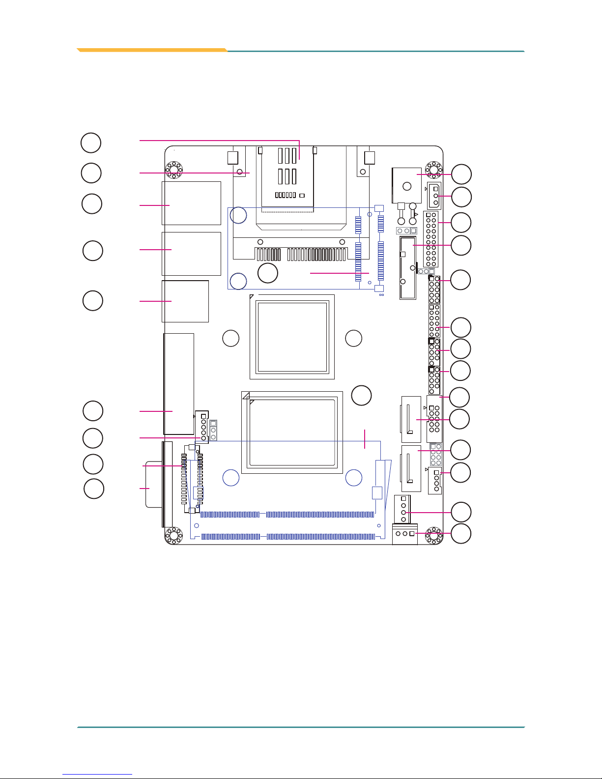
Connectors Location
C3
C7
C6
C2
C5
C1
PC17
PC1
S7
S1
1
1
1
2
3
1
8
7
2
1
15
10
9
22
9
10
10
9
2
30
4
2
3
12
2
10
9
2
19
202
PWR1
5
SMBUS1
6
JLPC1
7
JFRT1
9
AUDIO1
10
11
USB1
12
USB2
13
COM2
14
SATA2
16
CON1
15
SATA1
17
PWR2
18
CPUF1
22
DVI1
BAT1
8
23
USB3
24
LAN2
25
LAN1
26
CF1
27
SIM1
28
MC1
(Bottom Side)
29
DIMM1
(Bottom Side)
1
2
1715
18
16
51
52
14
203 204
72
74
71
73
12
19
COM1
21
INV1
20
LVDS1

- 9 -
Jumpers
JBAT1: Clear CMOS Setting (1)
Connector type: 2.54mm pitch 1x3-pin header
Pin Mode
1-2 Keep CMOS (Default)
23 1
2-3 Clear CMOS
23 1
JRS1: COM2 RS-232/422/485 Selection (3)
Connector type: 2.00mm pitch 2x4-pin header
Mode
RS-232 (Default)
RS-422 RS-485
1-2 Short Open Open
3-4 Open Short Open
5-6 Open Open Short
7-8 Short Open Open
87
21
87
21
87
2
1
JPWR1: AT/ATX Power Mode Selection (2)
Connector type: 2.54mm pitch 1x3-pin header
Pin Power Mode Selection
1-2 ATX Mode
23 1
2-3 AT Mode (Default)
23 1
JVLCD1: LVDS1 LCD Voltage Selection (4)
The voltage of LCD panel could be selected by JVLCD1
in +5V or +3.3V.
Connector type: 2.54mm pitch 1x3-pin header
Pin Voltage
1-2 +5V
23 1
2-3 +3.3V (Default)
23 1
PWR1: 4-pin ATX +12V Power Connector (5)
PWR1 supplies ATX +12V (Vcore).
Pin Description Pin Description
24
13
2GND 4 +12V
1GND 3 +12V
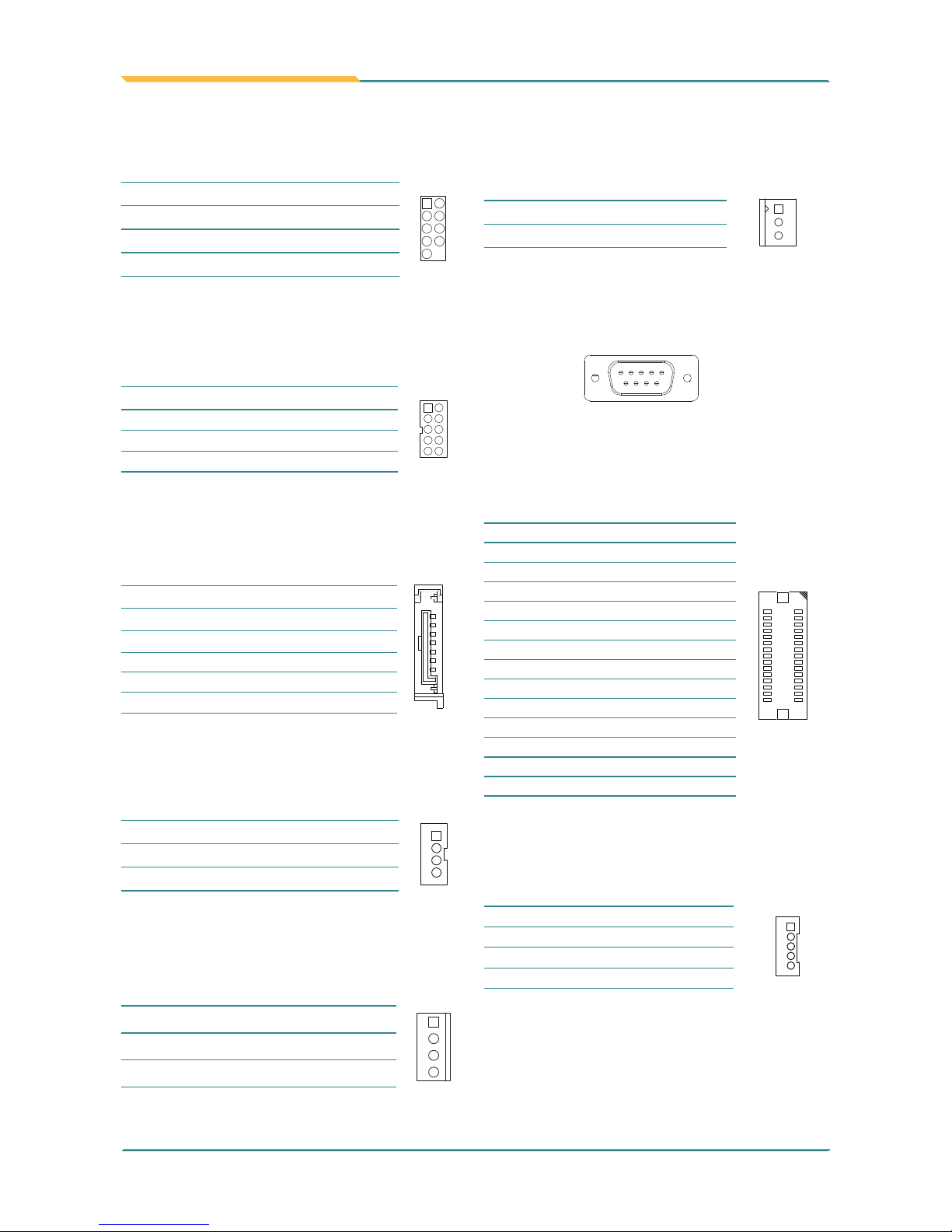
JFRT1: Front Panel (Switches and Indicators) (9)
It provides connectors for system indicators that
provides light indication of the computer activities
and switches to change the computer status.
Connector type: 2.00mm pitch 2x5-pin header
Pin Description Pin Description
109
1 2
1RESET+ 2RESET-
3 PLED+ 4 PLED-
5 HLED+ 6 HLED-
7 SPEAK+ 8 SPEAK-
9 PSON+ 10 PSON-
JLPC1: External LPC Connector (7)
Connector type: 2.00mm pitch 2x10-pin header
Pin Description Pin Description
19 20
1 2
1 5V 2 5V
3LPC_LDRQ# 4LPC_FRAME#
5INT_SERIRQ 6GND
7 LPC_AD2 8 LPC_AD3
9 LPC_AD0 10 LPC_AD1
11 PLT_RST# 12 GND
13 SMB DATA 14 CLK 33MHz
15 GND 16 SMB CLK
17 CLK 48MHz 18 PME#
19 3V 20 3V
Connectors
AUDIO1: Audio Connector (10)
Connector type: 2.00mm pitch 2x6-pin header
Pin Description Pin Description
11 12
1 2
1LINE-L 2LINE-R
3LINE_JD 4AGND
5MIC1L 6MIC1R
7 MIC1_JD 8 AGND
9LOUT-L 10 LOUT-R
11 LOUT_JD 12 AGND
BAT1: Battery Holder (8)
Pin Description
1
3
BAT1
2
1Battery power
2GND
3Battery power
SMBUS1: External SMBus Connector (6)
Connector type: 2.50mm pitch 1x3-pin box wafer connector
Pin Description
1
2
3
1 Data
2Clock
3GND
JRS1: COM2 RS-485 Auto-Flow Selection (3)
Connector type: 2.00mm pitch 2x4-pin headers.
Mode Enable Disable
7-8 Short Open
87
21
87
21
- 10 -
CPUF1: CPU Fan Connector (18)
CPUF1 is a 3-pin headers for the CPU fan. The fan
must be a +12V fan.
Pin Description
1
1GND
2 +12V
3FAN_Detect
USB1, 2: USB Port Connectors (11, 12)
Connector type: 2.00mm pitch 2x5-pin header
Pin Description Pin Description
109
1 2
1 5V 2 5V
3USB2/4- 4USB3/5-
5USB2/4+ 6USB3/5+
7 GND 8 GND
9 N/C 10 N/C
COM2: Serial Port Connector (13)
Connector type: 2.00mm pitch 2x5-pin box header
Pin Description Pin Description
109
1 2
1DCD#2 2RXD2
3TXD2 4DTR#2
5GND 6DSR#2
7 RTS#2 8 CTS#2
9RI2 10 N/C
LVDS1: LVDS LCD Panel Connector (20)
Connector type: ACES 1.25mm 87209-3040-06 connector
and supports 24-bit dual channels.
Pin Description Pin Description
1
2930
2
2 VDD 1 VDD
4TX2_CLK+ 3TX1_CLK+
6TX2_CLK- 5TX1_CLK-
8 GND 7 GND
10 TX2_D0+ 9 TX1_D0+
12 TX2_D0- 11 TX1_D0-
14 GND 13 GND
16 TX2_D1+ 15 TX1_D1+
18 TX2_D1- 17 TX1_D1-
20 GND 19 GND
22 TX2_D2+ 21 TX1_D2+
24 TX2_D2- 23 TX1_D2-
26 GND 25 GND
28 TX2_D3+ 27 TX1_D3+
30 TX2_D3- 29 TX1_D3-
PWR2: SATA Power Connector (17)
Connector type:
1x4-pin 2.54mm power connector
Pin Description
1
1 5V
2GND
3GND
4 12V
SATA1, 2: Serial ATA Connectors (15, 14)
High speed transfer rates (600MB/s).
Pin Description
1
7
1GND
2TX+
3TX-
4GND
5RX-
6RX+
7 GND
CON1: RS-422/485 Output Connector (16)
Connector type: 2.00mm pitch 1x4-pin box wafer connector
Pin RS-422 RS-485
1
1422TX+ DATA+
2422TX- DATA-
3422RX+ N/C
4422RX- N/C
INV1: LCD Inverter Connector (21)
Connector type: 2.00mm pitch 1x5-pin box wafer connector
Pin Description
1
5
1 +12V
2GND
3on/off
4Brightness control
5GND
COM1: Serial Port Connector (19)
Connector type: external 9-pin D-sub male connector
1 5
96

- 11 -
CF1: CFast Socket (26) (On Bottom Side)
Pin
Description
PC1
S7
S1
PC17
PC1
S7
S1
PC17
S1 SGND1
S2 TXP
S3 TXN
S4 SGND2
S5 RXN
S6 RXP
S7 SGND
PC1 CDI
PC2 GND
PC3 TBD
PC4 TBD
PC5 TBD
PC6 TBD
PC7 GND
PC8 LED1
PC9 LED2
PC10 IO1
PC11 IO2
PC12 IO3
PC13 3.3V
PC14 3.3V
PC15 GND
PC16 GND
PC17 CD0
SIM1: SIM Card Socket (27)
Connector type: Foxconn WL618E2-U05-7F CX1 socket
Pin Description
C3
C7
C6
C2
C5
C1
C1 VCC
C2 RST
C3 CLK
C5 GND
C6 VPP
C7 I/O
DVI1: DVI-I Display Connector (22)
Pin Description Pin Description Pin Description
1 DATA2- 9DATA1- 17 DATA0-
2 DATA2+ 10 DATA1+ 18 DATA0+
3DATA 2/4 SHIELD 11 DATA 1/3 SHIELD 19 DATA 0/5 SHIELD
4
DATA 4- (LINK 1, NC)
12
DATA 3- (LINK 1, NC)
20
DATA 5- (LINK 1, NC)
5
DATA 4+ (LINK 1, NC)
13
DATA 3+ (LINK 1, NC)
21
DATA 5+ (LINK 1, NC)
6DDC_CLK 14 +5V 22 Clock_SHIELD
7 DDC_DATA 15 GND (for +5V) 23 Clock+
8 VGA_V_Sync 16 Not Plug Detect 24 Clock-
C1 VGA Red
C2 VGA Green
C3 VGA Blue
C4 VGA_H_Sync
C5 VGA_R,G,B_Return
1 8
9 16
17
C1
C3
C2
C4
24
USB3: USB Port Connectors (23)
Connector type: double stack USB type A connector
LAN1, 2: Gigabit Ethernet Connectors (25, 24)
These connectors support Gigabit Ethernet.
DIMM1: DDR3 SO-DIMM Socket (29) (On Bottom Side)
203
204
1
2
DIMM1
MC1: Mini-card Socket (28) (On Bottom Side)
1
2
17
15
18
16
51
52

- 12 -
This page is intentionally left blank.
Table of contents


