Fodenn IPC-Q37MF Series User manual

IPC-Q37MF / IPC-C24MF
Series User’s Manual
No. G03-IPC-Q37MF Rev: 1.0
Release date: July 14, 2020
Trademark:
* Specifications and Information contained in this documentation are furnished for information use only, and are
subject to change at any time without notice, and should not be construed as a commitment by manufacturer.

ii
TABLE OF CONTENT
ENVIRONMENTAL SAFETY INSTRUCTION .......................................................................iii
ENVIRONMENTAL PROTECTION ANNOUCEMENT...........................................................iii
USER’S NOTICE..................................................................................................................iv
MANUAL REVISION INFORMATION...................................................................................iv
ITEM CHECKLIST................................................................................................................iv
CHAPTER 1 INTRODUCTION OF THE MOTHERBOARD
1-1 SPECIFICATION....................................................................................................1
1-2 LAYOUT DIAGRAM ...............................................................................................2
CHAPTER 2 HARDWARE INSTALLATION
2-1 JUMPER SETTING................................................................................................. 7
2-2 CONNECTORS AND HEADERS............................................................................ 11
2-2-1 REAR I/O BACK PANEL CONNECTORS................................................. 11
2-2-2 MOTHERBOARD INTERNAL CONNECTORS.......................................... 12
2-2-3 HEADER PIN DEFINITION........................................................................17
CHAPTER 3 INTRODUCING BIOS
3-1 ENTERNING SETUP..............................................................................................22
3-2 BIOS MENU SCREEN............................................................................................23
3-3 FUNCTION KEYS...................................................................................................23
3-4 GETTING HELP......................................................................................................24
3-5 MENU BARS..........................................................................................................24
3-6 MAIN MENU........................................................................................................... 24
3-7 ADVANCED MENU................................................................................................ 25
3-8 CHIPSET MENU.....................................................................................................37
3-9 SECURITY MENU ..................................................................................................40
3-10 BOOT MENU..........................................................................................................42
3-11 SAVE & EXIT MENU ..............................................................................................42

iii
Environmental Safety Instruction
Avoid the dusty, humidity and temperature extremes. Do not place the product in
any area where it may become wet.
0 to 40 centigrade is the suitable temperature. (The figure comes from the request
of the main chipset)
Generally speaking, dramatic changes in temperature may lead to contact
malfunction and crackles due to constant thermal expansion and contraction from
the welding spots’ that connect components and PCB. Computer should go
through an adaptive phase before it boots when it is moved from a cold
environment to a warmer one to avoid condensation phenomenon. These water
drops attached on PCB or the surface of the components can bring about
phenomena as minor as computer instability resulted from corrosion and oxidation
from components and PCB or as major as short circuit that can burn the
components. Suggest starting the computer until the temperature goes up.
The increasing temperature of the capacitor may decrease the life of computer.
Using the close case may decrease the life of other device because the higher
temperature in the inner of the case.
Attention to the heat sink when you over-clocking. The higher temperature may
decrease the life of the device and burned the capacitor.
Environmental Protection Announcement
Do not dispose this electronic device into the trash while discarding. To minimize
pollution and ensure environment protection of mother earth, please recycle.

iv
USER’S NOTICE
COPYRIGHT OF THIS MANUAL BELONGS TO THE MANUFACTURER. NO PART OF THIS MANUAL,
INCLUDING THE PRODUCTS AND SOFTWARE DESCRIBED IN IT MAY BE REPRODUCED, TRANSMITTED
OR TRANSLATED INTO ANY LANGUAGE IN ANY FORM OR BY ANY MEANS WITHOUT WRITTEN
PERMISSION OF THE MANUFACTURER.
THIS MANUAL CONTAINS ALL INFORMATION REQUIRED TO USE THIS MOTHER-BOARD SERIES AND WE
DO ASSURE THIS MANUAL MEETS USER’S REQUIREMENT BUT WILL CHANGE, CORRECT ANY TIME
WITHOUT NOTICE. MANUFACTURER PROVIDES THIS MANUAL “AS IS” WITHOUT WARRANTY OF ANY
KIND, AND WILL NOT BE LIABLE FOR ANY INDIRECT, SPECIAL, INCIDENTAL OR CONSEQUENTIAL
DAMAGES (INCLUDING DAMAGES FOR LOSS OF PROFIT, LOSS OF BUSINESS, LOSS OF USE OF DATA,
INTERRUPTION OF BUSINESS AND THE LIKE).
PRODUCTS AND CORPORATE NAMES APPEARING IN THIS MANUAL MAY OR MAY NOT BE
REGISTERED TRADEMARKS OR COPYRIGHTS OF THEIR RESPECTIVE COMPANIES, AND THEY ARE
USED ONLY FOR IDENTIFICATION OR EXPLANATION AND TO THE OWNER’S BENEFIT, WITHOUT
INTENT TO INFRINGE.
Manual Revision Information
Reversion
Revision History
Date
1.0
First Edition
July 14, 2020
Item Checklist
Motherboard
Cable(s)
I/O Back panel shield

1
Chapter 1
Introduction of the Motherboard
1-1 Specification
Spec
Description
Design
Micro ATX form factor; PCB size: 24.4 x24.4 cm
Chipset
IPC-Q37MF Series: Intel Q370 Express Chipset
IPC-C24MF Series: Intel C246 ExpressChipset
CPU
Socket
Intel® LGA 1151 Socket for Intel® 9th/8th
Generation Coffee Lake series
processors(TDP 95W)
CPU SKU for Q370 series: Core i7/i5/i3, Pentium, Celeron series
CPU SKU for C246 series: Xeon E, Core i7/i5/i3, Pentium, Celeron series
*
Note:
for detailed CPU support information please visit our website.
Memory
Slots
4*DDR4 U-DIMM slot for 4* DDR4 RAM Module
Support dual channel function
Maximum capacity: up to 128GB
Maximum frequency: up to 2666MHz(depends on CPU support)
*Note: C246 series supports DDR4 W/ECC SDRAM
Expansion
Slots
2 * PCI-Express x16 slot (*PCIE1/PCIE3)
*Note: PCIE1 slot share x16 lane band width with PCIE3 slot.
2 * PCI-Express x4 slot (PCIE2/PCIE4)
1* M.2 B-key slot, type-3042/3052,supports 3G/4G/5GModule(M2B)
1* M.2 E-key slot, type-2230,supports CNVi(M2E)
1* Nano SIM card holder(SIMCARD)
*Note: SIMCARD slot only work when compatible Nano SIM card installed
& 3G/4G/5G LAN card module installed in M2B slot.
Storage
IPC-Q37MF Series: 6*SATAIII 6Gb/s port support RAID0/1/5/10
(SATA1~SATA6, SATA6 co-lay M2M slot)
IPC-C24MF Series: 8*SATAIII 6Gb/s port support RAID0/1/5/10
(SATA1~SATA8, SATA6 co-lay M2M slot)
1* M.2 M-key slot,type-2242 SATA interface (M2M, co-lay SATA6)
1* M.2 M-key slot, type-2242/2260/2280/22110 supports NVMe
(NVM2M)
LAN Chip Integrated with 1* Intel i219-V & 1* Intel i210AT Gigabit PCI-E LAN
chips
Support Fast Ethernet LAN function of providing 10/100/1000Mbps
Ethernet data transfer rate
Audio Chip Realtek ALC662 6-CH Audio Codec integrated
Audio driver and utility included
BIOS
128M Bit AMI Flash ROM
Multi I/O
Rear Panel I/O:
1* RS232/422/485 COM port (COM1)
1* PS/2 keyboard & mouse combo port
1* DP port
1* HDMI port
1* VGA port (Co-lay LVDS)
1* DVI-D port

2
1-2 Layout Diagram
Rear IO Diagram
COM1
RS232/422/485
Serial Port VGA Port
Display Port
PS/2 Keyboard &
Mouse Combo Port
RJ-45 LAN Ports
Line-In
Line-Out
MIC
HDMI Port DVI-D Port USB3.1 (Gen.2)
Ports
4* USB 3.1 (Gen.2) port
2* RJ-45 LAN port
1*3-phone audio jack (Line-in, Line-out, MIC)
Internal I/O Connectors & Headers:
1*24-pin main power connector
1 *8-pin 12V power connector
1* CPUFAN connector & 2* SYSFAN connector
1* USB 2.0 port (Erect)
1* Front panel header
2* 9-Pin USB 2.0 header for 4* USB 2.0 expansion ports
1* 19-Pin USB 3.1 (Gen.1) header for 1* USB 3.1 (Gen.1) port &1*
USB 2.0 port
1* Front panel audio header
1* 16-bit GPIO header
1* SMBUS header
1* Parallel port header
5* COM port header (COM2:RS232/422/485;COM3/4/5/6:RS232 )
1* LVDS header+1* LVDS Inverter (Option/Co-lay VGA)

3
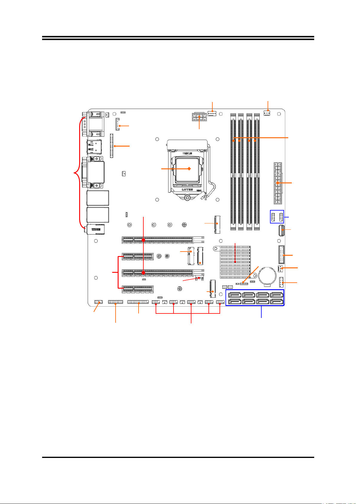
Motherboard Internal Diagram
IPC-Q37MF Series:
CPUFAN
Connector
SYSFAN1
Connector
*INVERTER
(Option)
ATX 12V
Power Connector
DDR4
*LVDS Header
(Option/Col-ay VGA) DIMM Slot x 4
*Rear IO
Connector
(Refer to Page-2)
LGA 1151
CPU Socket
ATX Power
Connector
PCI Express x4 Slot
(PCIE2/4)
PCI Express x16 Slots
(*PCIE1/3)
M.2 E-Key Slot
(M2E)
M.2 B-Key Slo t
(M2B)
Nano
M.2 M-Key Slot
(NVM2M)
Intel
Chipset
SMBUS Header
USB 2.0 Headers
USB 2.0 Port
(Erect)
USB 3.1(Gen.1)
Header
SYSFAN2
Connector
Front Panel
SIM Card Slot
M.2 M-Key Slot
(M2M)
Header
Front Panel
Audio
16-bit
Parallel Port
Header
Serial Port Headers
SATAIII Ports
(SATA1/2/3/4/5/*6)
GPIO Header (COM2/3/4/5/6)
*Note: 1.PCIE1 slot share x16 lane band width with PCIE3 slot. Configuration solutions: 1*PCIE x16
card, please plug in PCIE1 slot to run at x16 (Max.) lane band width; in the case that 2*PCIE cards
plugged in PCIE1 & PCIE3 slots, since the 2* PCIE slots share x16 lane band width, each card will run
at x8 (Max.) lane band width.2. SATA6 port co-lay with M2M, type-2242 slot; these two interfaces
cannot function at the same time, user can choose one of them to work via JP2 &JP3 jumper.3. LVDS
& INVERTER (together with JP5 & JP6) are by order option which co-lay with VGA port.
4
IPC-C24MF Series:
CPUFAN
Connector SYSFAN1
Connector
*INVERTER
(Option)
ATX 12V
Power Connector
DDR4
*LVDS Header
(Option/Col-ay VGA) DIMM Slot x 4
*Rear IO
Connector
(Refer to Page-2)
LGA 1151
CPU Socket
ATX Power
Connector
PCI Express x4 Slot
(PCIE2/4)
PCI Express x16 Slots
(PCIE1/3)
M.2 E-Key Slot
(M2E)
M.2 B-Key Slo t
(M2B)
Nano
M.2 M-Key Slot
(NVM2M)
Intel
Chipset
SMBUS Header
USB 2.0 Headers
USB 2.0 Port
(Erect)
USB 3.1(Gen.1)
Header
SYSFAN2
Connector
Front Panel
SIM Card Slot
M.2 M-Key Slot
(M2M)
Header
Front Panel
Audio
16-bit
Parallel Port
Header
Serial Port Headers
SATAIII Ports
(SATA1/2/3/4/5/*6/7/8)
GPIO Header (COM2/3/4/5/6)
*Note: 1.PCIE1 slot share x16 lane band width with PCIE3 slot. Configuration solutions: 1*PCIE x16
card, please plug in PCIE1 slot to run at x16 (Max.) lane band width; in the case that 2*PCIE cards
plugged in PCIE1 & PCIE3 slots, since the 2* PCIE slots share x16 lane band width, each card will run
at x8 (Max.) lane band width.2. SATA6 port co-lay with M2M, type-2242 slot; these two interfaces
cannot function at the same time, user can choose one of them to work via JP2 &JP3 jumper.3. LVDS
& INVERTER (together with JP5 & JP6) are by order option which co-lay with VGA port.

5
Motherboard Jumper Position:
JPCOM1
*JP5
(Option)
*JP6
(Option)
JP7
COPEN
JATX_AT
JPCOM3 JP2 JBAT
JPCOM2 JPCOM4 JP3
*Note: The diagrams in the manual are mostly taken from IPC-C24MF series unless otherwise stated.
Jumper
Jumper
Name
Description
JPCOM1
COM1 Port Pin9 Function Select
4-pin Block
JPCOM2
COM2 Header Pin9 Function Select
4-pin Block
JPCOM3
COM3 Header Pin9 Function Select
4-pin Block
JPCOM4
COM4 Header Pin9 Function Select
4-pin Block
JBAT
Clear CMOS RAM Settings
3-pin Block
JP7
Rear Panel UL1 USB Ports VCC Select
3-pin Block
JP2 &JP3
M2M Slot /SATA6 Select
3-pin Block
JAT_ATX
ATX/AT Mode Select
3-pin Block
COPEN
Case Open Message Display Detect
2-pin Block

6
JP5 (Option)
LVDS LCD Backlight VCC Select
3-pin Block
JP6 (Option)
LVDS LCD Panel VCC Select
4-pin Block
Connectors
Connector
Name
COM1
RS232/422/485 Serial Port Connector
PS2
PS2 Keyboard & Mouse Combo Port
DP_HDMI
Top: Display Port Connector
Bottom: High-Definition Multimedia Interface
Connector
CRT+DVI
Top: VGA Port Connector
Bottom: DVI-D Port Connector
UL1/UL2
Top:RJ-45 LAN Connector X2
Middle & Bottom: USB 3.1 (Gen.2) Port
Connector X4
AUDIO
Top: Line-in Connector
Middle: Line-out Connector
Bottom: MIC Connector
ATXPWR
ATX Type Main Power Connector
ATX12V
ATX 12V Power Connector
CPUFAN
CPU FAN Connector
SYSFAN1/2
System FAN Connector
IPC-Q37MF
Series:
SATA1~SATA6
SATAIII Connector X6
IPC-C24MF
Series:
SATA1~SATA8
SATAIII Connector X8
FP_USB3
USB 2.0 Port Connector (Internal Erect )
Headers
Header
Name
Description
FP_JW
(Front Panel Header)
PWR LED/ HD LED/ Power Button
/Reset
9-pin Block
FP_USB1/FP_USB2
USB 2.0 Port Header
9-pin Block
FP_USB30
USB 3.1 (Gen.1) & USB 2.0 Port
Header
19-pin Block
FP_AUDIO
Front Panel Audio Header
9-pin Block
GPIO_CON
GPIO Header
10-pin Block
PARALLEL
Parallel Port Header
25-pin Block
COM2
RS232/422/485 Serial Port Header
9-pin Block
COM3/4/5/6
RS232 Serial Port Header
9-pin Block
SMBUS
SMBUS Header
5-pin Block
LVDS (Option)
LVDS Header
30-pin Block
INVERTER(Option)
LVDS Inverter
6-pin Block

7
Chapter 2
Hardware Installation
2-1 Jumper Setting
JPCOM1 (4-pin): COM1 Port Pin9 Function Select
JPCOM 1
→
COM 1 Port Pin-9
1 2 1 2 1 2
3 4 3 4 3 4
5 6 5 6 5 6
2-4 Closed:
RI=RS232; 3-4 Closed:
RI= 5V; 4-6 Closed:
RI= 12V;
JPCOM2 (4-pin): COM2 Header Pin9 Function Select
JPCOM 2
→
COM 2 Header Pin-9
2 4 6
2 4 6
2 4 6
1 3 5
1 3 5
1 3 5
2-4 Closed:
RI=RS232;
3-4 Closed:
RI= 5V;
4-6 Closed:
RI= 12V.
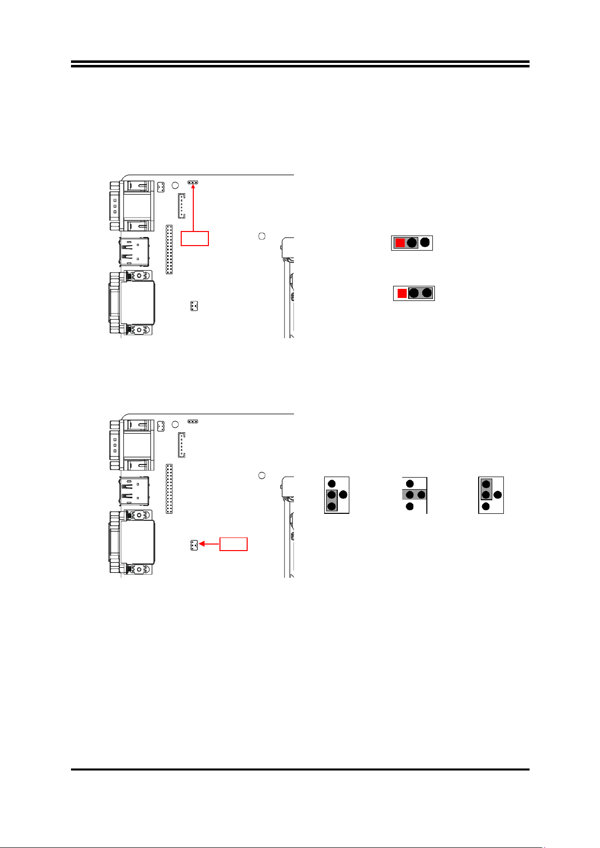
JPCOM3 (4-pin): COM3 Header Pin9 Function Select
JPCOM 3
→
COM 3 Header Pin-9
2 4 6
2 4 6
2 4 6
1 3 5
1 3 5
1 3 5
2-4 Closed:
RI=RS232;
3-4 Closed:
RI= 5V;
4-6 Closed:
RI= 12V.
COM3
COM2
COM1
JPCOM1
JPCOM2
JPCOM3
8
JPCOM4 (4-pin): COM4 Header Pin9 Function Select
JPCOM 2
→
COM 4 Header Pin-9
2 4 6
2 4 6
2 4 6
1 3 5
1 3 5
1 3 5
2-4 Closed:
RI=RS232;
3-4 Closed:
RI= 5V;
4-6 Closed:
RI= 12V.
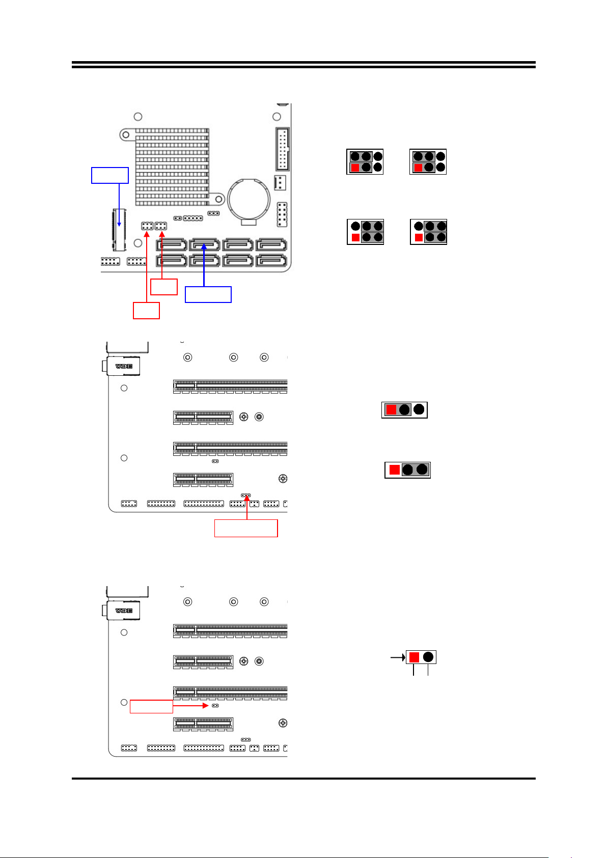
JBAT (3-pin): Clear CMOS RAM Settings
JBAT
→
Clear CMOS
1 3
1-2 Open: Normal;
1 3
1-2 Closed: Clear CMOS.
JP7 (3-pin): Rear Panel UL1 USB Ports VCC Select
JP7
→
UL1 USB Ports VCC
3
1
1-2 Closed: VCC;
3
1
2-3 Closed: 5VSB.
COM4
JBAT
JPCOM4
JP7
9
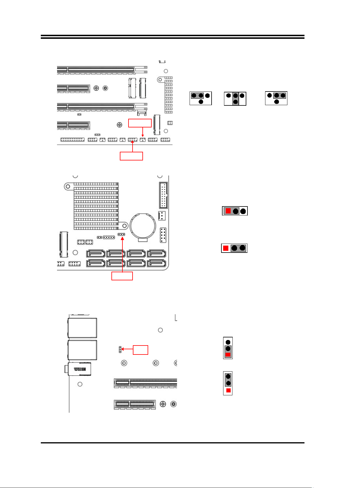
JP2 & JP3 (3-pin): M2M Slot/SATA6 Function Select
JP2 &JP3
→
M 2M Slot /SATA6 Select
2 4 2 4 6
1 3 5 1 3
JP2 & JP3 (1-3) (2-4)Closed:M2M Slot;
2 4 6 2 4 6
1 3 5 1 3 5
JP2 & JP3 (3-5) (4-6)Closed:SATA6.
JAT_ATX (3-pin): AT Mode /ATX Mode Select
JAT_ATX
→
ATX/AT Mode Select
1 3
1-2 Closed: ATX Mode Selected;
1 3
2-3
Closed: AT Mode Selected.
*ATX Mode Selected: Press power button to power on after power input ready;
AT Mode Selected: Directly power on as power input ready.
COPEN (2-pin): Case Open Message Display Function
COPEN
→
Case Open Detection
Pin1
JP2
JAT_ATX
SATA6
JP3
M2M
COPEN
GND
CASE OPEN
10
Pin 1-2 Short: When Case open function pin short to GND, the Case open function
was detected. When Used, needs to enter BIOS and enable ‘Case Open Detect’
function. In this case if your case is removed, next time when you restart your
computer, a message will be displayed on screen to inform you of this.
JP5 (3-pin): LVDS LCD BACKLIGHT VCC Select
JP5→LCD Backlight VCC Select
1 3
1-2 Closed: VCC= +5V;
1 3
2-3 Closed: VCC=+12V.
*Note: JP5 is only optional to customized models that come with LVDS & INVERTER.
JP6 (4-pin): LVDS LCD Panel VCC Select
JP6
→
LVDS LCD Panel VCC Select
6 5 6 5 6 5
4 3 4 3 4 3
2 1 2 1 2 1
2-4 Closed:
VCC= +12V 3-4 Closed:
VCC= +5V 4-6 Closed:
VCC= +3.3V
*Note: JP6 is only optional to customized models that come with LVDS & INVERTER.
JP5
JP6

11
2-2 Connectors and Headers
2-2-1 Rear I/O Back Panel Connectors
COM1
RS232/422/485
Serial Port
PS/2 Keyboard &
Mouse Combo Port
Display Port
VGA Port RJ-45 LAN Ports
Line-In
Line-Out
MIC
HDMI Port DVI-D Port USB3.1 (Gen.2)
Ports
Icon Name Function
RS232/422/485
Serial Port
Mainly for user to connect external MODEM or
other devices that supports
Serial Communications Interface.
PS/2 Keyboard &
Mouse Port
This combo port is for user to connect PS/2
mouse
or keyboard device to the board
Display Port
To the system to corresponding display device
with compatible DP cable.
HDMI Port
To connect display device that support HDMI
specification.
VGA Port
To connect display device that support VGA
specification.
DVI-D Port To connect display device that support DVI
specification
RJ-45 LAN Port This connector is standard RJ-45 LAN jack for
Network connection.
USB 3.1 (Gen.2)
Port
To connect USB keyboard, mouse or other
devices compatible with USB 3.1 (Gen.2)
specification. Ports support up to 10Gbps data
transfer rate.
Audio Connectors
BLUE: Line-in Connector
GREEN:Line-out Connector
PINK : MIC Connector

12
COM1 (9-pin Block): RS232/422/485 Port
COM1: RS232/422/485 Serial Port; The pin assignment for RS-232/ 422/ 485 is listed
as follows:
1 2 3 4 5
Pin1
Pin1
Pin1
6 7 8 9 RS422 Mode RS485 Mode
RS232 Mode
COM1 port can function as RS232/422/485 port. In normal settings COM1 functions
as RS232 port. With compatible COM cable COM1 can function as RS422 or RS 485
port. User also needs to go to BIOS to set ‘Transmission Mode Select’ for COM1 at
first, before using specialized cable to connect different pins of this port.
2-2-2 Motherboard Internal Connectors
(1) ATXPWR (24-pin block): Main Power Connector
ATX Power Supply connector: This is a new defined 24-pins connector that usually
comes with ATX case. The ATX Power Supply allows using soft power on momentary
switch that connect from the front panel switch to 2-pins Power On jumper pole on the
motherboard. When the power switch on the back of the ATX power supply turned on,
the full power will not come into the system board until the front panel switch is
momentarily pressed. Press this switch again will turn off the power to the system
board.
** We recommend that you use an ATX 12V Specification 2.0-compliant power
supply unit (PSU) with a minimum of 350W power rating. This type has 24-pin and 4-
pin power plugs.
** If you intend to use a PSU with 20-pin and 4-pin power plugs, make sure that the
20-pin power plug can provide at least 15A on +12V and the power supply unit has a
minimum power rating of 350W. The system may become unstable or may not boot
up if the power is inadequate.
** If you are using a 20-pin power plug, please refer to Figure1 for power supply
connection. Power plug form power supply and power connectors from motherboard
both adopt key design to avoid mistake installation. You can insert the power plug into
the connector with ease only in the right direction. If the direction is wrong it is hard to
fit in and if you make the connection by force if is possible.
GND
RS485 D+(A)
RS485 D-(B)
GND
RS422
RX(B)
RS422
RX(A)
RS422 TX(A)
RS422 TX(B)
GND
RS232 DTR#
RS232 SOUT
RS232 SIN
RS232 DCD#
RS232 RI#
RS232 CTS#
RS232 RTS#
RS232 DSR#

13
24-pin Main Power Connector
Figure1:20-pin power plug Figure 2:24-pin power plug
(2) ATX12V (8-pin block): 12V Power Connector
This is a new defined 8-pin connector that usually comes with ATX Power Supply that
supports extra 12V voltage to maintain system power consumption. Without this
connector might cause system unstable because the power supply can not provide
sufficient current for system.
4 Pin1
Pin
Definition
No.
Definition
1
GND
5
+12V
2
GND
6
+12V
3
GND
7
+12V
4
GND
8
+12V
PIN
ROW1
ROW2
1
+3.3V
+3.3V
2
+3.3V
-12V
3
GND
GND
4
+5V
Soft Power on
5
GND
GND
6
+5V
GND
7
GND
GND
8
Power OK
-5V
9
+5V Stand by
+5V
10
+12V
+5V
11
+12V
+5V
12
+3.3V
GND

14
(3) CPUFAN (4-pin): CPU Fan Connector
Pin1
(4) SYSFAN1 (3-pin): System Fan1 Connector
Pin1
(5) SYSFAN2 (3-pin): System Fan2 Connector
Pin1
GND
+12V Fan Power
Fan Speed
CPUFAN
SYSFAN1
SYSFAN2
Control
Fan Speed
+12V Fan
Power
GND
Fan Speed
+12V Fan Power
GND

15
SATA1
SATA5
SATA3
SATA4
*SATA6
SATA7
(Option)
SATA2
SATA8
(Option)
(6) SATA1~SATA8(7-pin): SATAIII Port connector
SATA7 & SATA8 are only optional for IPC-C24MF
series.
This is a high-speed SATAIII port that supports 6GB/s transfer rate.
*Note: SATA6 port co-lay with M2M, type-2242 slot; these two interfaces cannot
function at the same time, user can choose one of them to work via JP2 &JP3 jumper.
(7) NVM2M & M2M Slot: M.2 M-Key Slot
NVM2M M.2 M-Key slot supports compatible type-2242/2260/2280/22110 PCIE x4
SSD module.
M2M M.2 M-Key slot supports compatible type-2242 SATA module.
NVM2M Slot:
Pin No.
Definition
1
GND
2
TXP
3
TXN
4
GND
5
RXN
6
RXP
7
GND
M2M
M2M
NVM2M

16
NVM2M Slot Installation Guide:
1. Prepare compatible M.2 SATA or M.2 SSD card. Deferent type of cards has
different length. Find corresponding nut location for furtherinstallation.
Nut Location
MH1
MH2
MH3
MH4
Card Length
4.2 cm
6 cm
8 cm
11 cm
Module Type
Type- 2242
Type- 2260
Type- 2280
Type- 22110
2. Remove the screw post and nut fixed at
location MH4 by default (Skip step 2 & 3
and go straight to Step 4 if you are going
to use the default nut).
4. Align and insert corresponding M.2
module, as the photo shows.
3. Lock the screw post into the location
corresponding to the length of the
module.
5. Tighten up the screw to secure the
module into the M.2 connector. Mare
sure not overtighten the screw to avoid
possible damage to the module.
*Note: Please refer to Step-1/4/5 to install compatible M.2 type-2242 card into M2M
slot (SATA6 port co-lay with M2M, type-2242 slot; these two interfaces cannot
function at the same time, user can choose one of them to work via JP2 &JP3
jumper).
This manual suits for next models
1
Table of contents
Other Fodenn Motherboard manuals

Popular Motherboard manuals by other brands

MSI
MSI MS-98D3 user manual

Acrosser Technology
Acrosser Technology AR-ES0631ET installation guide

Gigabyte
Gigabyte GA-8IG1000MT user manual

Microchip Technology
Microchip Technology EVB-LAN9252-PICtail user guide

American Megatrends
American Megatrends MegaPlex II Specifications

Grantech
Grantech SYS86355VGGA-E user manual


