Emcore 10901G User manual

Operator's Manual
System 10000
Power Supply
Model 10901G
MAN-10901G Rev B
2015 Chestnut Street
Alhambra, California 91803
(626) 293-3400
Fax: (626) 293-3428
www.emcore.com

Emcore Corporation MAN-10901G Rev B
10901G Operating Manual Power Supply
2
Disclaimer
Every attempt has been made to make this material complete, accurate, and up-to-date. Users are cautioned, however,
that Emcore Corporation, reserves the right to make changes without notice and shall not be responsible for any
damages, including consequential, caused by reliance on the material presented, including, but not limited to,
typographical, arithmetical, or listing errors.
This manual describes the System 10000 Power Supply, model numbers:
Model Number Description Part Number
10901G-NA Power Supply 1901-001-001
10901G-EU Power Supply 1901-001-002
10901G-UK Power Supply 1901-001-003
10901G-NAB Power Supply, No Label 1901-002-001
10901G-EUB Power Supply, No Label 1901-002-002
10901G-UKB Power Supply, No Label 1901-002-003
Copyright Information
© 2008 by Emcore
Emcore Corporation
Alhambra, California, 91803, USA
March, 2008

Emcore Corporation MAN-10901G Rev B
10901G Operating Manual Power Supply
3
WARNINGS, CAUTIONS, AND GENERAL NOTES
Safety Considerations
When installing or using this product, observe all safety precautions during handling and operation. Failure
to comply with the following general safety precautions and with specific precautions described elsewhere in
this manual violates the safety standards of the design, manufacture, and intended use of this product.
Emcore Corporation assumes no liability for the customer's failure to comply with these precautions.
Calls attention to a procedure or practice, which if ignored, may result in damage to the system or system component.
Do not perform any procedure preceded by a CAUTION until described conditions are fully understood and met.
Electrostatic Sensitivity
ESD = Electrostatic Sensitive Device
Observe electrostatic precautionary procedures.
Semiconductor laser transmitters and receivers provide highly reliable performance when operated in
conformity with their intended design. However, a semiconductor laser may be damaged by an electrostatic
charge inadvertently imposed by careless handling.
Static electricity can be conducted to the laser chip from the center pin of the RF input connector, and
through the DC connector pins. When unpacking and otherwise handling the transmitter, follow ESD
precautionary procedures including use of grounded wrist straps, grounded workbench surfaces, and
grounded floor mats.
Exposure to electrostatic charge is greatly reduced after the transmitter has been installed in an operational
circuit.

Emcore Corporation MAN-10901G Rev B
10901G Operating Manual Power Supply
4
If You Need Help
If you need additional help in installing or using the system, need additional copies of this manual, or have
questions about system options, please call Emcore Corporation's Sales Department.
Service
Do not attempt to modify or service any part of the system other than in accordance with procedures outlined
in this Operator's Manual. If the system does not meet its warranted specifications, or if a problem is
encountered that requires service, return the apparently faulty plug-in or assembly to Emcore Corporation for
evaluation in accordance with Emcore Corporation's warranty policy.
When returning a plug-in or assembly for service, include the following information: Owner, Model Number,
Serial Number, Return Authorization Number (obtained in advance from Emcore Corporation's Customer
Service Department), service required and/or a description of the problem encountered.
Warranty and Repair Policy
The Emcore Corporation Quality Plan includes product test and inspection operations to verify the quality and
reliability of our products.
Emcore Corporation uses every reasonable precaution to ensure that every device meets published electrical,
optical, and mechanical specifications prior to shipment. Customers are asked to advise their incoming
inspection, assembly, and test personnel as to the precautions required in handling and testing ESD sensitive
opto-electronic components.
These products are covered by the following warranties:
1. General Warranty
Emcore Corporation warrants to the original purchaser all standard products sold by Emcore
Corporation to be free of defects in material and workmanship for one (1) year from date of shipment
from Emcore Corporation. During the warranty period, Emcore Corporation's obligation, at our
option, is limited to repair or replacement of any product that Emcore Corporation proves to be
defective. This warranty does not apply to any product, which has been subject to alteration, abuse,
improper installation or application, accident, electrical or environmental over-stress, negligence in
use, storage, transportation or handling.
2. Specific Product Warranty Instructions
All Emcore Corporation products are manufactured to high quality standards and are warranted
against defects in workmanship, materials and construction, and to no further extent. Any claim for
repair or replacement of a device found to be defective on incoming inspection by a customer must
be made within 30 days of receipt of the shipment, or within 30 days of discovery of a defect within
the warranty period.
This warranty is the only warranty made by Emcore Corporation and is in lieu of all other warranties,
expressed or implied, except as to title, and can be amended only by a written instrument signed by
an officer of Emcore Corporation. Emcore Corporation sales agents or representatives are not
authorized to make commitments on warranty returns.
In the even that it is necessary to return any product against the above warranty, the following
procedure shall be followed:

Emcore Corporation MAN-10901G Rev B
10901G Operating Manual Power Supply
5
a. Return authorization shall be received from the Emcore Corporation Sales Department
prior to returning any device. Advise the Emcore Corporation Sales Department of the
model, serial number, and the discrepancy. The device shall then be forwarded to Emcore
Corporation, transportation prepaid. Devices returned freight collect or without
authorization may not be accepted.
b. Prior to repair, Emcore Corporation Sales will advise the customer of Emcore Corporation
test results and will advise the customer of any charges for repair (usually for customer
caused problems or out-of-warranty conditions).
If returned devices meet full specifications and do not require repair, or if non-warranty
repairs are not authorized by the customer, the device may be subject to a standard
evaluation charge. Customer approval for the repair and any associated costs will be the
authority to begin the repair at Emcore Corporation. Customer approval is also necessary
for any removal of certain parts, such as connectors, which may be necessary for Emcore
Corporation testing or repair.
c. Repaired products are warranted for the balance of the original warranty period, or at least
90 days from date of shipment.
3. Limitations of Liabilities
Emcore Corporation's liability on any claim of any kind, including negligence, for any loss or
damage arising from, connected with, or resulting from the purchase order, contract, or quotation,
or from the performance or breach thereof, or from the design, manufacture, sale, delivery,
installation, inspection, operation or use of any equipment covered by or furnished under this
contract, shall in no case exceed the purchase price of the device which gives rise to the claim.
EXCEPT AS EXPRESSLY PROVIDED HEREIN, EMCORE CORPORATION MAKES NO WARRANTY OF
ANY KIND, EXPRESSED OR IMPLIED, WITH RESPECT TO ANY GOODS, PARTS AND SERVICES
PROVIDED IN CONNECTION WITH THIS AGREEMENT INCLUDING, BUT NOT LIMITED TO, THE
IMPLIED WARRANTIES OF MERCHANTABILITY AND FITNESS FOR A PARTICULAR PURPOSE.
EMCORE CORPORATION SHALL NOT BE LIABLE FOR ANY OTHER DAMAGE INCLUDING, BUT NOT
LIMITED TO, INDIRECT, SPECIAL OR CONSEQUENTIAL DAMAGES ARISING OUT OF OR IN
CONNECTION WITH FURNISHING OF GOODS, PARTS AND SERVICE HEREUNDER, OR THE
PERFORMANCE, USE OF, OR INABILITY TO USE THE GOODS, PARTS AND SERVICE.
Emcore Corporation will not be responsible for loss of output or reduced output of opto-electronic
devices if the customer performs chip mounting, ribbon bonding, wire bonding, fiber coupling, fiber
connectorization, or similar operations. These processes are critical and may damage the device or
may affect the device's output or the fiber output.
Emcore Corporation test reports or data indicating mean-time-to-failure, mean-time-between-failure,
or other reliability data are design guides and are not intended to imply that individual products or
samples of products will achieve the same results. These numbers are to be used as management
and engineering tools, and are not necessarily indicative of expected field operation. These
numbers assume a mature design, good parts, and no degradation of reliability due to
manufacturing procedures and processes.
Emcore Corporation is not liable for normal laser output degradation or fiber coupling efficiency
degradation over the life of the device.

Emcore Corporation MAN-10901G Rev B
10901G Operating Manual Power Supply
6
Table of Contents
Chapter 1 GENERAL DESCRIPTION
Introduction......................................................................................................................................................................... 1-1
System Applications............................................................................................................................................................ 1-1
System Description............................................................................................................................................................. 1-1
System Specifications......................................................................................................................................................... 1-2
Chapter 2 INSTALLATION AND SETUP PROCEDURES
Introduction......................................................................................................................................................................... 2-1
Unpacking and Inspecting the System................................................................................................................................ 2-1
Installing System Assemblies.............................................................................................................................................. 2-1
Chapter 3 OPERATION PROCEDURES
Introduction......................................................................................................................................................................... 3-1
LED Indicators .................................................................................................................................................................... 3-1
Monitors and Alarms........................................................................................................................................................... 3-1
Pin Assignments................................................................................................................................................................. 3-2
Chapter 4 MAINTENANCE AND TROUBLESHOOTING
Introduction......................................................................................................................................................................... 4-1
Routine Maintenance Procedures....................................................................................................................................... 4-1
Troubleshooting Procedures............................................................................................................................................... 4-1
Emcore Corporation MAN-10901G Rev B
10901G Operating Manual Power Supply
7
Chapter 1 GENERAL DESCRIPTION
Introduction
This Operator’s Manual is intended to aid in the configuration, installation, operation, and maintenance of the System 10000
10901GPower Supply. Included is a general description, theory of operation, information and procedures for performance
verification, operation, troubleshooting and maintenance. The information applies to all 10901G models.
System Applications
This plug-in power supply for the Emcore Corporation System 10000 supplies 60 Watts total power to drive up to eight 7.5
Watt Emcore Corporation plug-in units.
System Description
The Power Supply is part of a modular, rack-mounted assembly. The assembly fits a standard 19 inch rack. They plug-in at
each end and accept standard AC power to produce all DC power required by all other system plug-ins.
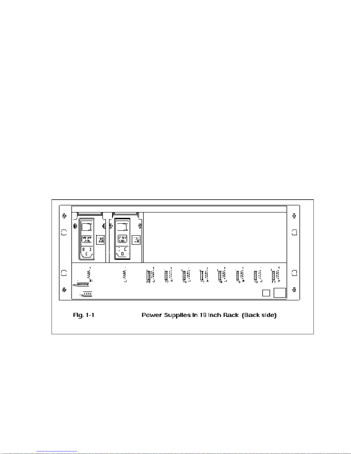
The basic Assembly (see block diagram, Figure 1-1) is comprised of the following plug-ins:
Plug-In Chassis Assembly, which supports and interconnects the various system components.
Redundant Power Supplies, which provides system DC power automatically and instantaneously is switched into the
system if a Power supply fails.
Emcore Corporation MAN-10901G Rev B
10901G Operating Manual Power Supply
8
System Specifications
10901G Power supply
Output Voltage Tol. Load Max.
Ripple and Noise
Line Regulation Load Regulation
+5.3V +0.2V
-0.1V 6 A 120 mV p-p 0.4% 2%
+15.2V +0.2V
-0.4V 2 A 150 mV p-p 0.4% 1%
-15.0 Vdc N/A 0.5 A 150 mV p-p 0.4% 1%
Available Continuous Power 60 W @ 50°C (derates linearly to 70% at 60°C)
Input Voltage 85 to 264 Vac
Input Frequency 47 to 440 Hz
Inrush Current (Cold) 30 A at 100 Vac
60 A at 200 Vac
Operating Temperature -10 to +60°C
Storage Temperature -20 to +75°C
Overload Protection Works over 105% of rated current and recovers automatically.
Mechanical Parameters
Dimensions 3 U x 14 HP x 220 mm (5.25 x 2.4 W x 8.66 D) (1 HP = one
horizontal position = 0.2”; 1 U = 1 rack unit = 1.75”)
Weight 2.25 0.25 lbs.
Emcore Corporation MAN-10901G Rev B
10901G Operating Manual Power Supply
9
Chapter 2 INSTALLATION AND SETUP PROCEDURES
Introduction
This section contains information and procedures for installing the Model 10901G Power Supply, and for preparing it for
operation.
Unpacking and Inspecting the System
Unpack the system carefully; thoroughly inspecting the equipment to assure that no damage has occurred in shipment. If
damage is found, notify the responsible carrier and Emcore Corporation immediately.
Carefully check the contents of the shipment against the shipping list. Notify Emcore Corporation if there is an apparent
discrepancy.
Installing System Assemblies
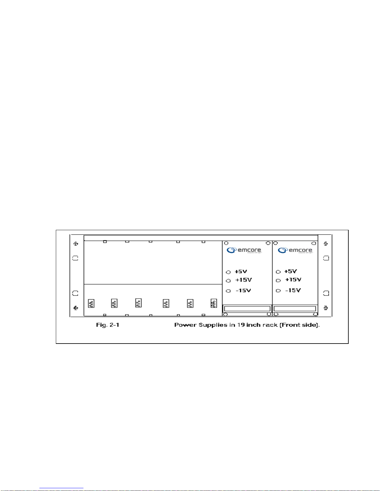
Install each assembly in a standard NEMA 19-inch rack, with the10901G Power Supplies in the last two slots, (see fig 2-1).
Use an approved AC power cord UL listed (supplied with unit) to an AC outlet. Unit will accept both 110 and 230 VAC. Turn
switch on and verify LED’s to be ON.
This completes setup and installation procedures. The system is now ready for normal operation.
10901G 10901G

Emcore Corporation MAN-10901G Rev B
10901G Operating Manual Power Supply
10
Chapter 3 OPERATION PROCEDURES
Introduction
The system normally operates without operator intervention. Periodic checking of LED voltage indicators will help keep the
system running without interruption. During normal operation, it is recommended to check the system every six hours.
LED Indicators
Visually monitor the following LED indicators. All should be on (green) whenever the system is operating.
+5V
+15V
-15V
If any indicator is off, the monitored item has either failed or operating parameters are outside specified limits. Refer to
Maintenance and Troubleshooting for maintenance procedures.
CAUTION
If the Laser Temperature indicator is off, disconnect the Transmitter Plug-In immediately to reduce the possibility of
further damage to the Transmitter.
Monitors and Alarms
It is the user’s responsibility to utilize monitor and alarm outputs provided on the system. Monitoring these outputs, and
logging readings periodically, will provide an early warning that maintenance is required to avoid system failure or
degradation.

Emcore Corporation MAN-10901G Rev B
10901G Operating Manual Power Supply
11
10901G
Model 10990A Chassis, Main Power Supply Status Connector (P11 – P18))
Pin - Chassis Pin - Connector Description
1 5 See individual unit manua
2 4 See individual unit manua
3 3 See individual unit manua
4 2 See individual unit manua
5 1 No Connection
Mating Connector 5148-025 (Supplied with 10990A Chassis)
Crimp Pins 5231-001(Not Supplied with 10990A
Chassis)
Emcore Corporation MAN-10901G Rev B
10901G Operating Manual Power Supply
12
Model 10990A Chassis Power Supply Status Connector (P19)
Pin
Chassis
Pin
Connector
Description PS 1 OFF PS 1 ON PS 2. OFF PS 2. ON
1 8 No
connection
2 7 No
connection
3 6 PS 2. Status
(NO) closed open
4 5 PS 2 Status
(Common)
5 4 PS 2 (NC open closed
6 3 PS 1Status
(Common)
7 2 PS 1 Status
(NC)
closed open
8 1 PS 1 Status
(NO)
open closed
Mating Connector 5148-004 (Supplied with 10990A Chassis)
Crimp Pins 5231-001(Not Supplied with 10990A Chassis)
The voltages from the main power supply may be monitored and used directly with connector P20.
Model 10990A Chassis, Main Power Supply Status Connector (P20)
Pin Description
1 +5 V DC
2 +15 V DC
3 -15 V DC
4 GND
Mating Connector 5148-026 (Supplied with 10990A Chassis)
Crimp Pins 5231-004(Not Supplied with 10990A Chassis)
Chapter 4 MAINTENANCE AND TROUBLESHOOTING
Introduction
This section contains information for maintaining and troubleshooting the system.

Emcore Corporation MAN-10901G Rev B
10901G Operating Manual Power Supply
13
Routing Maintenance Procedures
The equipment requires no routine maintenance. However, vigilant monitoring of LED indicators, and monitor and alarm
outputs, may detect an incipient problem and permit corrective maintenance before a failure occurs.
Troubleshooting Procedures
System failure or degradation is normally indicated by system indicators, monitors and alarms.
Note: Contact Emcore Corporation to return apparently failed plug-ins for repair. Plug-ins must be repaired only by
qualified, factory-trained personnel.
Refer to Installation and Setup Procedures for information and procedures for measuring signal levels and performance.
Table of contents


