Emec PRIUS P User manual

MOTOR DRIVEN PLUNGER METERING PUMP
OPERATING MANUAL
EN
PRIUS P
SS PUMP HEAD
PP PUMP HEAD

2
THIS OPERATING INSTRUCTIONS CONTAINS SAFETY INFORMATION THAT IF IGNORED CAN
ENDANGER LIFE OR RESULT IN SERIOUS INJURY.
READ THESE INSTRUCTIONS CAREFULLY BEFORE USEAND KEEP THEM FOR FUTURE REFERENCE.
THE ORIGINAL INSTRUCTION IS IN ENGLISH.
INFORMATION AND SPECIFICATIONS ON THIS MANUAL COULD BE UNCORRECT OR COULD HAVE
PRINTING ERRORS.
SPECIFICATIONS ARE SUBJECT TO CHANGE WITHOUT NOTICE.
Version: R1-03-17
NORME CE
EC RULES (STANDARD EC)
NORMAS DE LA CE
Direttiva Bassa Tensione
Low Voltage Directive
Directiva de baja tensión
Direttiva EMC Compatibilità Elettromagnetica
EMC electromagnetic compatibility directive
EMC directiva de compatibilidad electromagnética
Norme armonizzate europee nell’ambito della direttiva
European harmonized standards underdirective
Las normas europeas armonizadas conforme a la directiva
2014/35/UE
2014/30/UE
⎬
⎬
2006/42/CE
⎬

SUMMARY
GENERAL SAFETY GUIDELINES......................................................... 4
1. DESCRIPTION............................................................................... 5
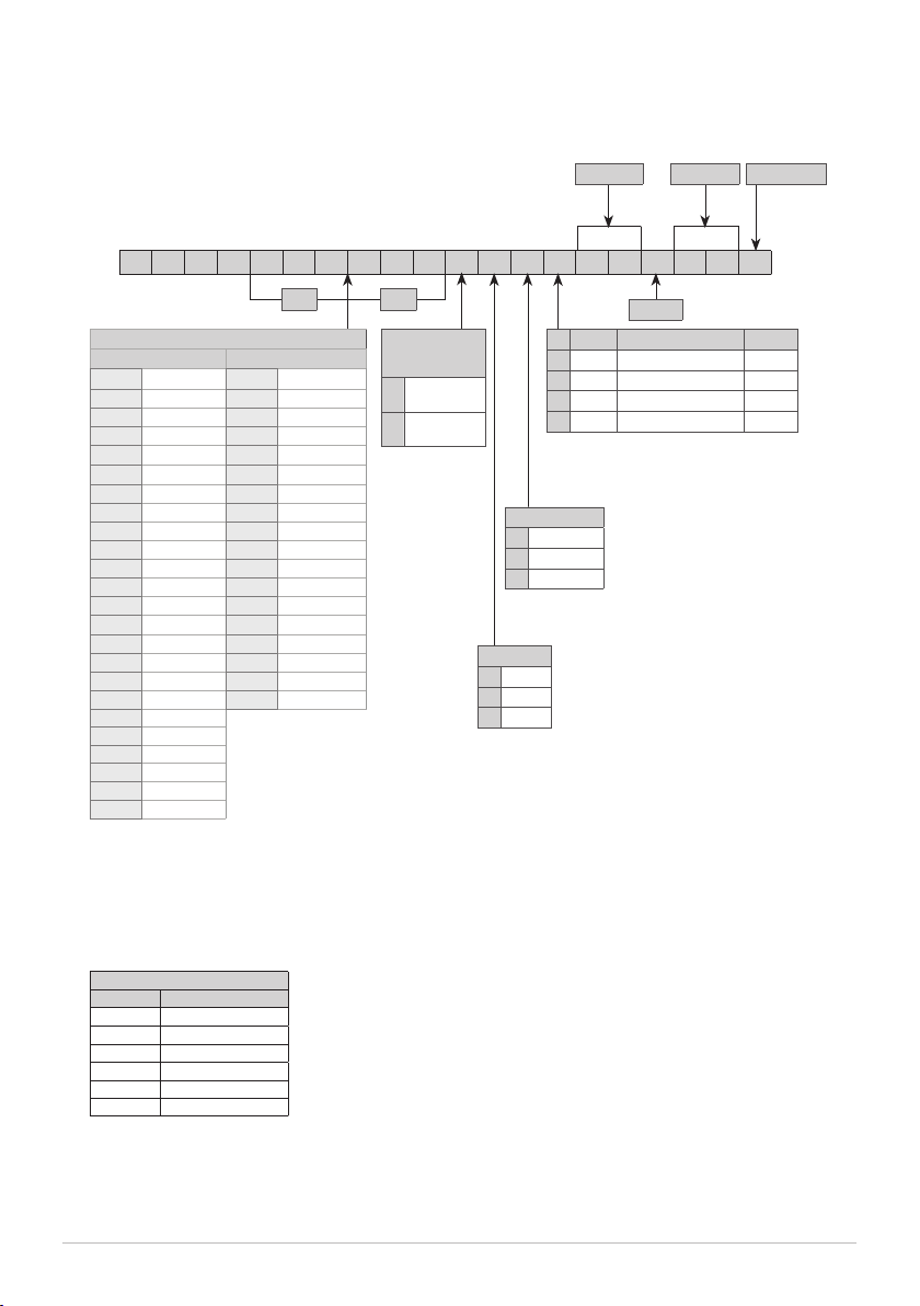
1.1 PRIUS Series............................................................................ 5
1.3 Features .................................................................................. 8
1.3.1 PLUNGER............................................................................. 9
2. INSTALLATION.............................................................................. 12
2.1 Installation warning................................................................. 12
2.2 Commissioning steps.............................................................. 13
2.2.1 Pump location...................................................................... 13
2.2.2 Oil filling .............................................................................. 13
2.2.3 Piping connection................................................................. 14
2.2.4 Pump head .......................................................................... 14
2.2.5 Foot filter ............................................................................. 14
2.2.6 Installation drawings............................................................ 15
3. ELECTRICAL WIRING .................................................................... 16
3.1 Preliminary checks................................................................... 16
3.2 Connection diagrams............................................................... 16
4. START UP18
4.1 Start up................................................................................... 18
5. PRIMING 19
5.1 How to prime the pump .......................................................... 19
6. MAINTENANCE............................................................................ 20
6.1 Maintenance schedule............................................................. 20
6.2 Maintenance inspection .......................................................... 20
6.3 Shutdown ............................................................................... 21
7. TROUBLESHOOTING ..................................................................... 22
7.1 Repair service.......................................................................... 22
8. COMPATIBILITY TABLE ................................................................. 23
8.1 Chemical compatibility table.................................................... 23
8.2 Materials................................................................................. 23
Figures
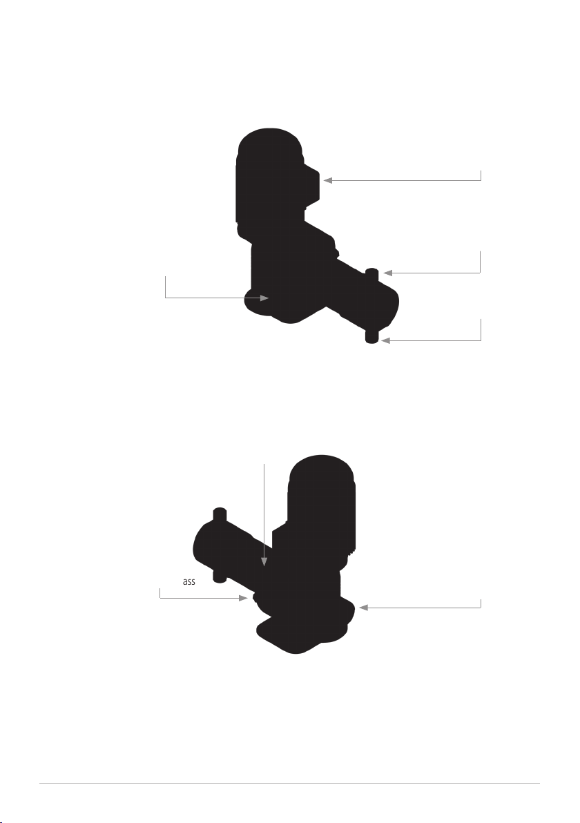
Fig. 1. PRIUS P pump ............................................................... 7
Fig. 2. Installation drawings ..................................................... 15
Tables
Tab. 1. Capacity............................................................................ 8
Tab. 2. PRIUS P - PP pump head.................................................... 10
Tab. 3. PRIUS P - SS pump head .................................................... 11
Tab. 4. Acceptable oil for lubricating.............................................. 13
Tab. 5. Guide to troubleshooting. .................................................. 22
Tab. 6. Chemical compatibility table............................................... 23

4
GENERAL SAFETY GUIDELINES
Operating, installing, or maintaining the unit in any way that is not covered in this manual could
cause death, serious personal injury, or damage to the equipment.
METERING PUMP IS INTENDED FOR CHEMICAL DOSING.
Use of this pump with radioactive chemicals is FORBIDDEN!
Keep the pump protected from sun and water. Avoid water splashes.
In EMERGENCIES the pump should be switched off immediately! Disconnect the power
cable from the power supply!
When using pump with aggressive chemicals observe the regulations concerning the
transport and storage of aggressive fluids!
Adequate measures shall be taken to prevent cross connection of chemicals!
Chemical feeding must be stopped during BACKWASH CYCLES AND PERIODS OF
NOFLOW as these conditions may introduce the potential for chemical OVERDOSING.
Not doing so may result in elevated chemical concentrations and hazerdous gas
introduction into the piping, pool or spa.
Never operate any pumping system with a BLOCKED SUCTION AND DISCHARGE.
You must take all necessary measures to avoid this condition.
When installing always observe national regulations!
Manufacturer is not liable for any unauthorized use or misuse of this product that may
cause injury, damage to persons or materials.
Pump must be accessible at all times for both operating and servicing. Access must
not be obstructed in any way!
Feeder should be interlocked with a no-flow protection device to automatically
shut-off the pumps when there is no flow!
Pump and accessories must be serviced and repaired by QUALIFIED AND AUTHORIZED
PERSONNEL ONLY!
Before any operation:
• always read chemical Material Safety Data Sheet (MSDS);
• always wear protective clothing;
• always discharge the liquid end before servicing the pump!
• empty and rinse the liquid end before work on a pump which has been used with
hazardous or unknown chemicals!
Danger!
Indicates a hazardous situation which, if not avoided, will result in death or serious injury.
Warning!
Indicates a hazardous situation which, if not avoided, could result in death or serious injury
Important - A practice not related to personal injury or additional information.
This manual use the following safety message icon:
ICON

5
1.1 PRIUS Series PRIUS series is a motor-driven plunger series pumps with spring return mechanism.
The plunger produces the flow thanks to the suction and delivery valves on the pump head
PRIUS is a constant dosing pump.
Flow rate is determined by the stroke length. The stroke length is adjustable from 0 to 100% using
the stroke length adjustment knob.
1. DESCRIPTION
Some functions described into this manual may need accessories not included into the
pump packaging.
PLEASE DO NOT TRASH PACKAGING. IT CAN BE USED TO RETURN THE PUMP.

6
1.2 Identification Code
LUBRICANT TYPE
BRAND MODEL
MOBIL MOBILGEAR 632
SHELL OMALA OIL 320
BP ENERGOL GR-XP 320
IP MELLANA OIL 320
ESSO SPARTAN EP 320
AGIP BLASIA 320
PP00010024DV1200N000
BAR L/H
MOTOR POWER SUPPLY PHASE
10,18Kw 220-240/380-420 - 50/60 Hz 3-PHASE
20,37Kw 220-240/380-420 - 50/60 Hz 3-PHASE
30,18Kw 220/380 - 60 Hz 3-PHASE
40,37Kw 220/380 - 60 Hz 3-PHASE
COLOR
PACKAGING INTERNALCUSTOM.
CAPACITY
50 Hz 60 Hz
010024 24 l/h @ 10 bar 010023 23 l/h @ 10 bar
010013 13 l/h @ 10 bar 010011 11 l/h @ 10 bar
010010 10 l/h @ 10 bar 010005 5 l/h @ 10 bar
010005 5 l/h @ 10 bar 010076 76 l/h @ 10 bar
010080 80 l/h @ 10 bar 010038 38 l/h @ 10 bar
010043 43 l/h @ 10 bar 010019 126 l/h @ 10 bar
010032 32 l/h @ 10 bar 010126 126 l/h @ 10 bar
010016 16 l/h @ 10 bar 010063 63 l/h @ 10 bar
010130 130 l/h @ 10 bar 010031 31 l/h @ 10 bar
010070 70 l/h @ 10 bar 010195 195 l/h @ 10 bar
010052 52 l/h @ 10 bar 010097 97 l/h @ 10 bar
010026 26 l/h @ 10 bar 010048 48 l/h @ 10 bar
010210 210 l/h @ 10 bar 010300 300 l/h @ 10 bar
010113 113 l/h @ 10 bar 010150 150 l/h @ 10 bar
010084 84 l/h @ 10 bar 010075 75 l/h @ 10 bar
010042 42 l/h @ 10 bar 007469 469 l/h @ 7 bar
010320 320 l/h @ 10 bar 007234 234 l/h @ 7 bar
010172 172 l/h @ 10 bar 007117 117 l/h @ 7 bar
010128 128 l/h @ 10 bar
010064 64 l/h @ 10 bar
007508 508 l/h @ 7 bar
007273 273 l/h @ 7 bar
007203 203 l/h @ 7 bar
007101 101 l/h @ 7 bar
MATERIAL
pump head +
plunger
DPP + CERAMIC
(SIALOX 96)
ESS (AISI316L) +
SS (AISI420)
O RING
VFKM B
DDutral
WWAX
REDUCTION GEAR
18:1
215:1
420:1

7
Fig. 1. PRIUS P pump
Stroke lenght knob
Oil sight glass
Oil cap (inlet)
Power supply
Suction vale
Delivery valve
Oil outlet

8
1.3 Features Power supply.................................................................220-240/380-420 V - 50 Hz 3-PHASE
.....................................................................................220/380 V - 60 Hz 3-PHASE
Aluminium enclosure (epoxy coating)
Ceramic (SIALOX96 ) or stainless steel (AISI420) plunger
Environment temperature: -10 ÷ 40°C (14 ÷ 104°F)
Chemical temperature with SS pump head: -10 ÷ 90°C (14 ÷ 194°F)*
Chemical temperature with PP pump head: -10 ÷ 40°C (14 ÷ 104°F)
Installation class ...........................II
Pollution level ...............................2
Audible noise................................78 dbA (± 5 dB)
Protection degree..........................IP 55
Max suction height........................3 m
Oil capacity ...................................0,3 lt (Refer to “Lubricant type” table)
Dosing accuracy ...........................± 5% at rated pressure.
* The specified temperature can be exceeded temporarily (max 15’) for sterilization or flushing with
hot water.
Tab. 7. Reduction factor for different site altitudes.
Site altitude above
sea level Site altitude above sea level coolant temperature
m <30 °C 30 °C … 40 °C 45 °C
1000 1,07 1 0,96
1500 1,04 0,97 0,93
2000 1 0,94 0,9
2500 0,96 0,9 0,86
3000 0,92 0,86 0,82
3500 0,88 0,82 0,79
4500 0,82 0,77 0,74

9
1.3.1 PLUNGER Prius P plunger pumps.
Material: ceramic (SIALOX96) or Stainless Steel (AISI420)
Lenghts available: 14, 25, 32, 40, 50.

10
Tab. 8. PRIUS P - PP pump head
PRIUS P 50 Hz
stroke length PLUNGER
diam. (mm) PRIUS P 50 Hz Stroke/1’ Pressure
bar
Capacity
l/h Motor
HOSES
CONNECTION INSTALLATION
KIT
PP
15 mm
14
010024 175
10
24
0,18 kW G1/2"
12x18 A
010013 94 13
010010 70 10
010005 35 5
25
010080 175
10
80
0,18 kW G1/2"
12x18 A
010043 94 43
010032 70 32
010016 35 16
32
010130 175
10
130
0,18 kW G1/2"
12x18 A
010070 94 70
010052 70 52
010026 35 26
40
010210 175
10
210
0,37 kW G3/4”
d.i. 18 mm B
010113 94 113
010084 70 84
010042 35 42
50
010320 175
10
320
0,37 kW G3/4”
d.i. 18 mm B
010172 94 172
010128 70 128
010064 35 64

11
Tab. 9. PRIUS P - SS pump head
PRIUS P 50 Hz
stroke length PLUNGER
diam. (mm) PRIUS P 50 Hz Stroke/1’ Pressure
bar
Capacity
l/h Motor
HOSES
CONNECTION
SS
15 mm
14
010024 175
10
24
0,18 kW R1/2”
010013 94 13
010010 70 10
010005 35 5
25
010080 175
10
80
0,18 kW R1/2”
010043 94 43
010032 70 32
010016 35 16
32
010130 175
10
130
0,18 kW R1/2”
010070 94 70
010052 70 52
010026 35 26
40
010210 175
10
210
0,37 kW R3/4”
010113 94 113
010084 70 84
010042 35 42
50
010320 175
10
320
0,37 kW R3/4”
010172 94 172
010128 70 128
010064 35 64
63
007508 175
7
508 0,55 kW
R1”
007273 94 273
0,37 kW007203 70 203
007101 35 101

12
PRIUS P WITH PP PUMP HEAD AND CERAMIC PLUNGER
60 HZ / 3-PHASE MOTOR
PRIUS P WITH SS PUMP HEAD AND PLUNGER
60 HZ / 3-PHASE MOTOR
PRIUS P 60 Hz
stroke length PLUNGER
diam. (mm) PRIUS P 60 Hz Stroke/1’ Pressure
bar
Capacity
l/h Motor
HOSES
CONNECTION INSTALLATION
KIT
PP
15 mm
14
010023 175
10
23
0,18 kW G1/2"
12x18 A010011 87 11
010005 44 5
25
010076 175
10
76
0,18 kW G1/2"
12x18 A010038 87 38
010019 44 19
32
010126 175
10
126
0,18 kW G1/2"
12x18 A010063 87 63
010031 44 31
40
010195 175
10
195
0,37 kW G3/4”
d.i. 18 mm B010097 87 97
010048 44 48
50
010300 175
10
300
0,37 kW G3/4”
d.i. 18 mm B010150 87 150
010075 44 75
PRIUS P 60 Hz
stroke length PLUNGER
diam. (mm) PRIUS P 60 Hz Stroke/1’ Pressure
bar
Capacity
l/h Motor
HOSES
CONNECTION
SS
15 mm
14
010023 175
10
23
0,18 kW R1/2”010011 87 11
010005 44 5
25
010076 175
10
76
0,18 kW R1/2”010038 87 38
010019 44 19
32
010126 175
10
126
0,18 kW R1/2”010063 87 63
010031 44 31
40
010195 175
10
195
0,37 kW R3/4”010097 87 97
010048 44 48
50
010300 175
10
300
0,37 kW R3/4”010150 87 150
010075 44 75
63
007469 175
7
469 0,55 kW
R1”007234 87 234 0,37 kW
007117 44 117

13
2. INSTALLATION
Before start installation, the operator must be aware of safety precautions to prevent physical injury.
OPERATOR PROTECTION
Use safety equipment according to the company regulations.
Use this safety equipment within the work area during installation, service and
when handling chemicals:
• protective mask
• protective gloves
• safety goggles
• ear plugs or hear muffs
• further security device, if necessary.
POWER SUPPLY DISCONNECTION
Always disconnect power to the motor before you perform any installation or
maintenance tasks. Failure to disconnect power will result in serious physical
injury.
2.1 Installation
warnings
INSTALLATION PUMP GUIDELINES
Install the pump
- in a safety place and fixed to the table / wall to avoid vibration problems;
- in an easy accessible place;
- in horizontal position.
Use only hoses compatibles with product to dose.
See “8.1 Chemical compatibility table” page 24.
If dosing product is not listed please consult full compatibility table or contact chemical’s
manufacturer.

14
Pump must be installed on a flat base at max 3 m height from tank’s bottom.
Fasten the pump by clamping screws.
Injection point must be higher of tank to avoid accidental chemical injection.
Otherwise, connect a multifunction valve on delivery pipeline.
2.2.1 Pump location
2.2.2 Oil filling Pumps are shipped WITH OIL AND WITH A BLIND CAP.
At the job site you must replace the blind cap with the one supplied.
KEEP THE BLIND CAP for further shipping.
Fill the oil reservoir through oil inlet (“Fig. 2. Oil filling”).
The required amount of oil is 0,30 lt. For acceptable lubricants see the table below.
Check oil level regularly. Change the oil every 8.000-10.000 operating hours.
You must never start the pump without oil.
BRAND LUBRICANT TYPE
MOBIL MOBILGEAR 632
SHELL OMALA OIL 320
BP ENERGOL GR-XP 320
IP MELLANA OIL 320
ESSO SPARTAN EP 320
AGIP BLASIA 320
Tab. 10. Acceptable oil for lubricating
Fig. 2. Oil filling
2.2
Commissioning
steps
5 steps of installation procedure:
1. Pump location
2. Oil filling
3. Piping connection
4. Electric wiring
5. Start-up
Oil sight glass
Oil cap (inlet)
Oil outlet

15
Suction piping should be as short as possible and installed in vertical position to
avoid air bubbles suction.
2.2.3 Piping
connection
Suction and delivery valves must be installed in vertical position.
Hand-tighten the nuts firmly.
Do not use tongs or any other tool.
Delivery hose must be firmly fixed to avoid suddenly movements that could
damage near objects
Never operate any pumping system with a blocked suction and discharge. Operation,
even for a brief period under these conditions, can cause motor to overheat.
You must take all necessary measures to avoid this condition.
2.2.4 Pump head Pump head priming procedure described in “5. PRIMING” page 20.
PP pump head or SS pump head available.
2.2.5 Foot filter Foot filter is always recommended.
Foot filter should be adequate to suction piping and installed al least 10 cm from the tank bottom.

16
Fig. 3. Installation drawings
2.2.6 Installation
drawings
,IWKHLQMHFWLRQYDOYHRIWKH3ULXVòLVDVVHPEOHGRUXVHGLQOLQHGRQRWDSSO\WKHRULQJWRSUHYHQWLW
IURPUXQQLQJLQWRWKHV\VWHP,QVWDOORULQJRQO\ZKHQILWWLQJLQWRDV\VWHPZKLFKKDVDQRULQJIOXVK

17
3.1 Preliminary
checks
The electrical wirings should be carried out by AUTHORIZED AND QUALIFIED
PERSONNEL only in accordance with local regulations.
Before to proceed, verify the following steps:
1. Verify the data on nameplate.
Make sure that the electrical data on the nameplate of the motor corresponds to the
electrical supply.
2. Verify the grounded power outlet.
The pump must be plugged to a grounded power outlet.
3. Install a motor protection switch.
Pump must be connected to a motor protection switch (Residual Current Circuit Breaker -
MCCB).
4. Verify the cable.
Cable type and cross-section must be in accordance to motor data.
5. Verify the motor rotation.
Start up the pump to check the motor’s direction of rotation. It must comply with that
indicated by the arrow marked on the motor fan cover. If the direction is reversed, rewire
the motor power wires in accordance with the wiring diagram, refer to “3.2 Connection
diagrams”.
3.2 Connection
diagrams
CONNECTION DIAGRAMS for 3∼PHASE MOTOR 50 Hz
PE
L1 L2 L3
U1 V1 W1
W2 U2 V2
“Y” CONNECTION
380-420 Vac
PE
L1 L2 L3
U1 V1 W1
W2 U2 V2
“∆“ (DELTA) CONNECTION
220-240 Vac
3. ELECTRICAL WIRING

18
L1
L1
N
N
U1
U1
V1
V1
W1
W1
W2
W2
U2
U2
V2
V2
CONNECTION DIAGRAMS for 1∼PHASE MOTOR
MOTOR SUITABLE FOR INSERTIONS WITH RANGE OF AT LEAST 6” INTERVAL

19
4.1 Start up All operation before described must be carried out before starting the pump.
1. Pump location
2. Oil filling
3. Piping connection
4. Electric wiring
Follow the “GENERAL SAFETY GUIDELINES” PAGE 4.
1. Start the pump at minimum pressure.
2. Turn the stroke lenght knob on 20%.
3. After 5 minutes, gradually increase the capacity until reaching the prescribed value for the
operating condition.
Control the pressure correspond to the one on the nameplate. If not, stop the
pump immediatly.
If the pump does not start to dose:
a) Stop the pump.
b) Prime the pump head (“5. PRIMING” PAGE 20)
c) Start the pump again.
4. Monitor periodically the pump functioning.
4. START UP

20
5.2 How to prime
the pump
The first time and where use of the pump is suspended for a long period of time, priming may be
necessary. It allows suction piping and pump head to fill with liquid before pumping against pressure.
Priming the pump is also recommended when there is air into pump head or into suction pipe.
Feeder should be interlocked with a no-flow protection device to automatically
shut-off the pumps when there is no flow!
Adequate measures shall be taken to prevent cross connection of chemicals!
Chemical feeding must be stopped during backwash cycles and periods of noflow
as these conditions may introduce the potential for chemical overdosing. Not
doing so may result in elevated chemical concentrations and hazerdous gas intro-
duction into the pool or spa.
Never operate any pumping system with a blocked suction and discharge.
You must take all necessary measures to avoid this condition.
SAFETY EQUIPMENT
Use safety equipment according to the company regulations. Use this safety
equipment within the work area:
• Helmet
• Safety goggles (with side shields)
• Protective shoes
• Protective gloves
• Gas mask
1. Connect all pipings (suction, delivery).
2. Rotate stroke lenght knob (pull and rotate) on 100%;
3. Power the pump.
4. When the chemical starts to flow into discharge hose, close discharge knob.
5. Proceed to standard operating condition.
5. PRIMING
5.1 Warnings
Table of contents
Other Emec Water Pump manuals