Emec TMS DC Series Instruction Manual

1
OPERATING INSTRUCTION MANUAL
FOR “TMS DC” AND “TMSA DC” SERIES PUMPS
ENGLISH Version
R1-06-10
This operating instructions contains safety information that if ignored can endanger life or result in serious injury. They
are indicated by this icon.
Use of this pump with radioactive chemicals is forbidden!
Keep the pump protected from sun and water.
Avoid water splashes.
Read Carefully!

2
Danger!
GENERAL SAFETY GUIDELINES
In emergencies the pump should be switched off immediately! Disconnect the power cable from the
power supply!
When using pump with aggressive chemicals observe the regulations concerning the transport and
storage of aggressive fluids!
When installing always observe national regulations!
Manufacturer is not liable for any unauthorized use or misuse of this product that may cause injury,
damage to persons or materials.
Caution! Pump must be accessible at all times for both operating and servicing. Access must not be obstructed in
any way!
Feeder should be interlocked with a no-flow protection device.
Pump and accessories must be serviced and repaired by qualified and authorized personnel only!
Always discharge the liquid end before servicing the pump!
Empty and rinse the liquid end before work on a pump which has been used with hazardous or unknown
chemicals!
Always read chemical safety datasheet!
Always wear protective clothing when handling hazardous or unknown chemicals!
“TMS DC” series solenoid dosing pumps comply with the following European regulations:
EN60335-1 : 1995, EN55014, EN50081-1/2, EN50082-1/2, EN6055-2, EN60555,3
Based on directive CEE 73/23 c 93/68 (DBT Low voltage directive) and directive 89/336/CEE (EMC
Electromagnetic Compatibility)

3
1. Introduction
1.1 Introduction
Metering Pumps “TMS DC” (TMSA DC self-venting model) Series are the ideal solution for low / middle dosing of chemicals.
All control and setup parameters are available through a digital keyboard and they are displayed on a LCD backlit display. Pump has got:
“Standby” input, “LEVEL” input and “Alarm” (contact) output.
Note: some functions described into this manual may need accessories not included into the pump packaging.
1.2 Pump’s capacity
Flow rate is determined by the stroke length and by the stroke speed.
1. 3 Working modes
Pump can work in CONSTANT mode.
CONSTANT mode.
Pump doses at a constant rate set in “SPH” (strokes for hour), “SPM” (strokes for
minute) or “LPH” (litres per hour) parameters set during program session.

4
2. Unpacking
Included into package:
n.2 Dibbles ø6
n.2 Self tapping screws 4,5 x 40
n.1 Delayed fuse 5 X 20
n.1 Level probe with axial foot filter (PVDF)
n.1 Injection valve
m 2 Delivery pipe (PVDF)
m 2 Suction pipe (transparent PVC)
m 2 Discharge pipe (transparent PVC)
m 2,5 Signal cable for “Stand-by” and “Alarm”
n.1 This installation manual
* If hose is 6x8 there is only a 4meters long hose.
Cut to obtain suction and delivery hoses.
Remove the contents from the box.
PLEASE DO NOT TRASH PACKAGING.
IT CAN BE USED TO RETURN THE PUMP.

5
3. Pump’s description
* Note:if knob isn’t on 100% position
then the pump will dose at pressure greater
than the one declared on label.
**See page 13 for “Stand-by” and “Alarm”
connections.
To delivery hose
To suction hose
To discharge hose
Discharge knob
Pump head
** “Stand-by” and “Allarm” connections
Power supply
Level probe input

6
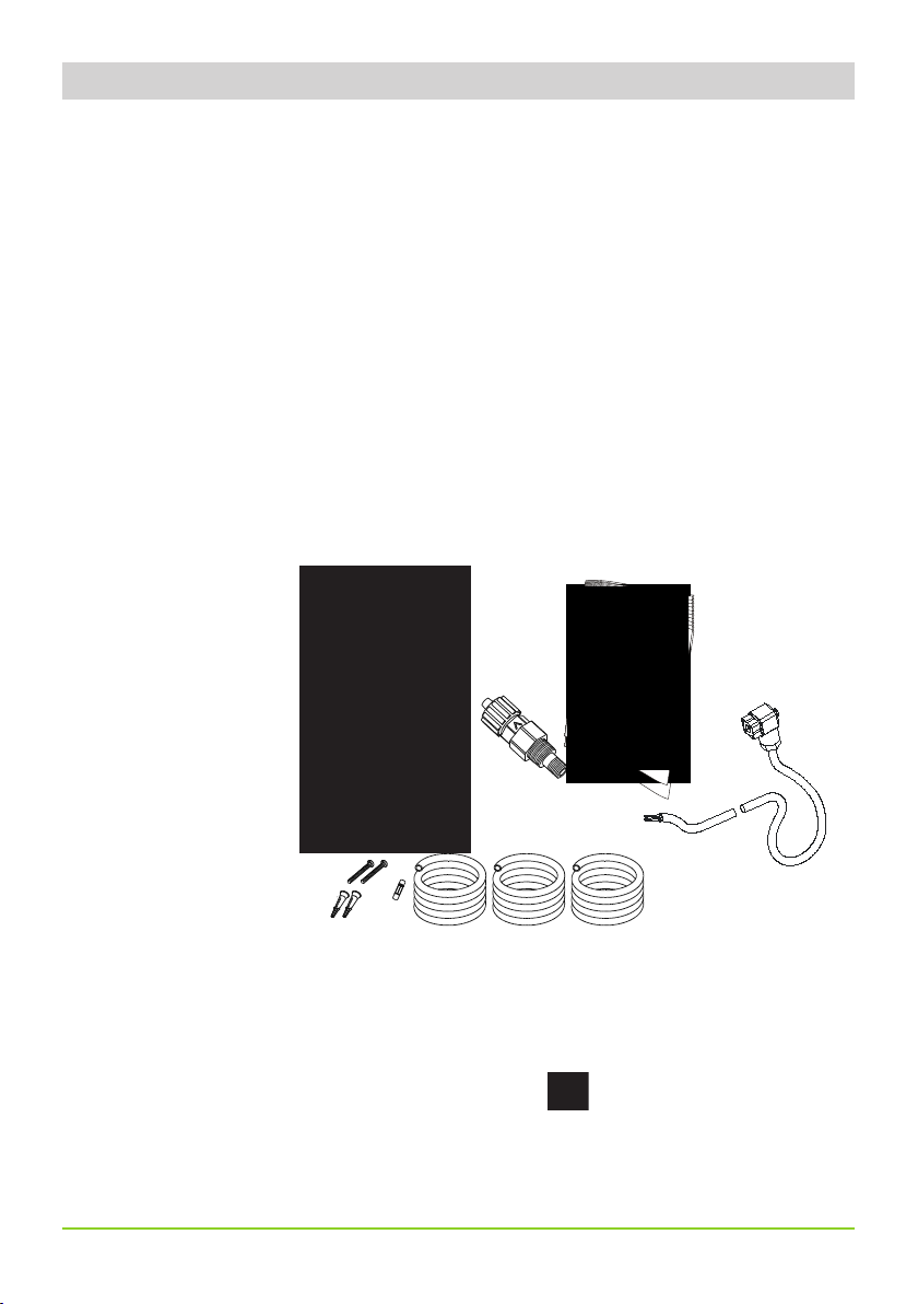
Pump’s installation and operativity is made in 4 main steps:
Pump’s installation
Hydraulic Installation (hoses, level probe, injection valve)
Electrical Installation (main power connection, priming)
Programming the pump.
Before to start, please read carefully the following safety information.
Protective clothes
Wear always protective clothes as masks, gloves, safety glasses and
further security devices during ALL installation procedure and while
handling chemicals.
Installation location
Pump must be installed in a safety place and fixed to the table / wall to
avoid vibration problems!
Pump must be installed in a easy accessible place!
Pump must be installed in vertical position!
Avoid water splashes and direct sun!
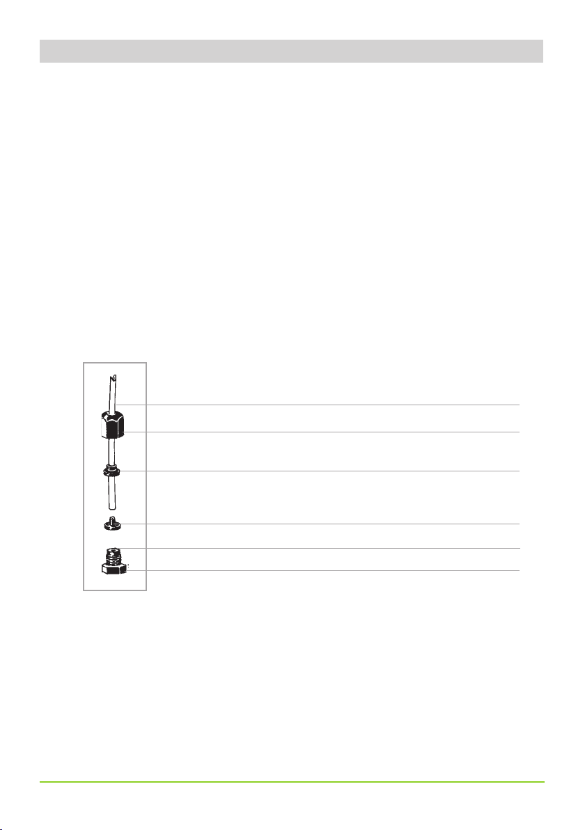
Hoses and Valves
Suction and delivery hoses must be installed in vertical position!
All hoses connections must be performed using only hands’ force!
No tongs required!
Delivery hose must be firmly fixed to avoid suddenly movements
that could damage near objects!
Suction hose must be shorter as possible and installed in vertical
position to avoid air bubbles suction!
Use only hoses compatibles with product to dose! See chemical
compatibility table. If dosing product is not listed please
consult full compatibility table or contact chemical’s manufacturer!
4. Before to Install warnings
Feeder should be interlocked with a no-flow protection device to automatically shut-off the
pumps when there is no flow!
Adequate measures shall be taken to prevent cross connection of chemicals!
Chemical feeding must be stopped during backwash cycles and periods of noflow as these con-
ditions may introduce the potential for chemical overdosing. Not doing so may result in elevated
chemical concentrations and hazerdous gas introduction into the pool or spa.

7
Pump must be installed in a wall support at a maximum height (from tank’s bottom) of 1,5 meters.
1 - Dosing Pump
2 - Suction Hose
3 - Delivery Hose
4 - Injection Valve
5 - Air discharge
6 - Level Probe
7 - Foot Filter
8 - Power Cable
9 - Standby / Alarm
1
2
3
4
5
6
7
8
9
5. Installation draw

8
Suction Hose
Tightening Nut
Holding Ring
Pipe Holder
O-ring
Valve
Hydraulic connections are:
Suction Hose with level probe and foot filter
Delivery Hose with injection valve
Discharge Hose
6.1 Suction Hose.
Completely unscrew tightening nut from pump’s head and remove assembling
components: tightening nut, holding ring and pipe holder.
Assembly as shown in fig. (A). Insert hose into pipe holder until it reaches the
bottom.
Lock hose on pump’s head by screwing down the tightening nut.
Use only hands to do it!
Connect other side of the hose to the foot filter using the same procedure.
fig. (A)
6. Hydraulic installation

9
6.2 Assembling foot filter with level probe.
Level probe must be assembled with foot filter using the provided kit.
Foot valve is made to be installed into tank’s bottom without sediments priming problem.
Connect BNC from level probe into pump’s level input (front side of the pump).
Put level probe assembled with foot filter into tank’s bottom.
Warning: If there is a mixer installed into tank, install a suction lance
instead of level probe / foot filter.
6.3 Delivery Hose.
Completely unscrew tightening nut from pump’s head and remove assembling
components: tightening nut, holding ring and pipe holder.
Assembly as shown in fig. (A). Insert hose into pipe holder until it reaches the bottom.
Lock hose on pump’s head by screwing down the tightening nut.
Use only hands to do it!
Connect other side of the hose to the injection valve using the same procedure.
Progettato da Controllato da Modificato da, il Data
Edizione Foglio
/
076.0147.1
Massimo_F 24/10/2003
00
Toll. Gen.
`0.05
Materiale:
STEP 5
FILTRO DI ASPIRAZIONE CON
SONDA DI LIVELLO - CONTATTO N.O.
FP+CE+PVDF
1 1
STEP 2
INSERT FLOATER
STEP 1
INSERT RING AS SHOWN
STEP 4
INSERT RING AS SHOWN
STEP 3
INSERT PROBE
WITH N.O. CONTACT
UNTIL TO HEAR
A CLICK

10
6.5 Discharge hose.
Insert one side of discharge hose into discharge connector as shown in fig (C).
Insert other side of discharge hose into product’s tank.
During priming procedure product exceeding will flow into tank.
For priming procedure see page 16.
Discharge hose
Discharge Knob
fig (C)
6.4 Injection Valve.
Injection valve must be installed on plant from water’s input.
Injection valve will open at pressure greater than 0,3bar.
1
1
2
2
3
3
4
4
5
5
6
6
7
7
8
8
A A
B B
C C
D D
E E
F F
Progettato da Controllato da Modificato da, il Data
Edizione Foglio
/
A2emec_Modificato
Massimo_F 27/01/2010
00
Toll.
Gen.
`0.05
Materiale:
1
1
to suction hose
to delivery hose

11
7.1 Self-venting pump head.
Self-venting pump head must be used when using chemicals that produce
gas (i.e. hydrogen peroxide, ammonium, sodium hypoclorite at particular conditions).
Hoses assembling procedure (including purge hose) is described in fig. (A).
Notes:
- suction, delivery and purge valves are DIFFERENT! Do not exchange them!
- delivery and purge hoses are made of same material!
- it’s allowed to lightly bend discharge hose!
- during calibration procedure (“TEST”) insert discharge hose into BECKER
test-tube!
to suction hose
to delivery hose
7. Self-Venting pump head installation
1
1
2
2
3
3
4
4
5
5
6
6
7
7
8
8
A A
B B
C C
D D
E E
F F
Progettato da Controllato da Modificato da, il Data
Edizione Foglio
/
A2emec_Modificato
Massimo_F 27/01/2010
00
Toll.
Gen.
`0.05
Materiale:
1
1
Discharge hose

12
All electrical connections must be performed by AUTHORIZED AND QUALIFIED personnel only.
Before to proceed, please, verify the following steps:
- verify that pump’s label values are compatible with main power supply.
- pump must be connected to a plant with a differential switch (0,03A
sensitivity) if there isn’t a good ground.
- to avoid damages to the pump do not install it in parallel with heavy
inductance load (for example: engines). A relay switch must be used. See
below picture.
P- Dosing Pump
R- Relay
I - Switch or safety device
E- Electrovalve or inductance load
A- Main Power
8. Electrical Installation

13
Once verified previous steps proceed as follows:
- check that “BNC” of level probe has been connected as described in “Hydraulic
Installation” chapter.
- connect alarm and/or stand-by signal as described below fig (D):
fig (D)
1
4
1: (Green) “Stand-by” Input
4: (Yellow) “Stand-by” Ground
2: (Brown) Alarm (Relay) Common
3: (White) N.O.Alarm(Relay) Contact
Max load relay output: 2A 250VAC
2
3
Notes: - “Alarm” signal isn’t fuse protected
- “Standby” signal has main priority on
pump’s enabling / disabling.
Level Probe Input

14
The “TMS DC” pump is equipped with a keyboard.To avoid any misunderstanding during next chapters all keys will be described
as shown on this legend:
“UP” key “ESC” key
“RIGHT” key “E” key
Menu navigation:
To enter into programming mode press and keep pressed “E” key from main screen (fig.3):
Main screen (fig.3) may appear different if “PPM” or “BATCH” mode is enabled. After about 4 seconds the pump will show
the password screen (fig.5):
Default password is “0000”. Just press “E” key. Otherwise insert password using “UP” and “RIGHT” keys.
E
ESC
fig.3
password
0000 fig.5
ON/OFF
STROKES
100 SPM
batch
waiting
upkeep
000m 00s
LCD backlit display
Turn the pump on or off and exit from setup menu (without saving parameters)
Enter / exit from setup menu (saving parameters)
Scroll and increase digit
TMS DC
9. Basic settings

15
OFF
------------------
Saving / Discarding changes / Activating working mode
Once edited data into setup menu it’s possible to save them by pressing “E” key or to discard them by pressing “ESC” key.
To activate the working mode (Constant) select the required mode and confirm it using “E” key.
Turning on and off the pump
“ESC” key has a double function. It can be used to discard all changes made into setup mode or to turn on/off the pump. To
turn on/off the pump press and keep pressed this key while in main screen (fig.3). The pumps will show:
To return into operating mode press “ESC” key.
Alarm output logical working.
The pump has an “Alarm” output that changes its status (from N.O. to N.C. or viceversa) when a signal is received from “LEVEL”
and/or “SEFL” and/or “STAND-BY”. To set this alarm refer to related chapter.
Full menu / Short Menu mode
When entering into SETUP display shows access mode menu:
If this is the first time into SETUP menu then the pump will automatically set itself into “FULL” menu mode as shown in fig. A.
Just press “E” key to confirm. This mode will show all pump functions and working modes.
Next time the SETUP menu will be reached it will possible to operate with “SHORT” menu configuration to change only selected
mode parameters as shown in fig. B. Press “E” to confirm.
Note: “SHORT” menu option is not available during first time into SETUP menu or after a reset.
fig.6
FULL
MENU
SHORT
MENU
fig. A fig. B

16
the pump will show the “Delay” (pump’s activation delay) as shown fig.2:
Press any key to skip the “Delay”. Pump will show “Srokes” (actual strokes) as shown in fig.3:
In any working mode, if a SEFL is installed and enabled (see SEFL Setup procedure), the display will show the icon (asterisk
as in fig. 4):
- if SEFL works correctly, the asterisk blinks to any pulses given by the solenoid;
- if the asterisk does not appear, there is an anomaly (i.e.: hoses and/or valves are obstructed, SEFL in not connected, etc.).
Press and keep pressed the “RIGHT” key to enter into priming mode. Pump will go for 30 seconds into priming mode as shown
in fig.5.
When the chemical begins to flow out from the outgassing hose then completely close the outgassing knob (except for self-
venting pump heads). This ends the priming procedure. If countdown for priming is not yet ended press “ESC” key.
Now the pump is operative. Proceed to setup and programming.
fig.1
fig.2
fig.3
fig.4
PRIMING
To proceed follow these steps: connect all hoses to the pump; open dischage valve by completely turning the discharging knob
(counter clock-wise). Power up the pump and turn stroke lenght knob to 100%. After pump’s intro (fig.1):
*
tMS dc
R: 1.xx
WAITING
00:59
STROKES
100 SPM
STROKES
100 SPM
PRIMING
30 Sec. fig.5
10. Priming

17
Pump’s functions summary
During pump’s working mode is it possible to see furthers working information.
Press more times the “UP” key to cycle through following information:
key
key
key
Working Mode
Power Supply Voltage
key
key
constant
150 spm
key
cc/st
0.20
STROKES
100 SPM
MODE
constant
SUPPLY
220 VAC
DOSING
0.000 lph
Liters/Hour or Gallons/ Hour
Dosage
11. Pump’s functions summary

18
This diagram shows all the
possible alarms.
ALARM
LEVEL
Key
Key
ALARM
STD-By
Key
Key
ALARM
stroke
ALARM
POWER
If any alarm is active, in the menù “Pump’s functions summary” a general alarm display will show the number of alarm active
at the moment. Enter into this menu with “RIGHT” key.
The windows displayed show which alarms are active.
Level alarm: the level probe signals the product
end.
Stand-by alarm signals the pump stop.
Power alarm signals the power supply is out of
range (from 180 to 260 VAC).
Stroke alarm signals that it has been set a capacity
higher than the value on the label.
Key
ALARM
N° 01
STROKES
100 SPM
SUPPLY
220 VAC
DOSING
0.000 lph
Key
Key
Key
Key
Key
MODE
divide
12. Pump’s functions summary- ALARMS

19
Key
PROG [2]
SETUP
PROG [3]
STAT
Key
E
Key
E
Key
See
page 19
E
Key
See
page 20
Key
PROG [1]
MODE EKey
Mode [1]
CONSTANT
See
page 34
13. Quick Guide - Main Menu (Prog [1] Mode)

20
E
Key
E
Key
E
Key
Key
Key
Key
PROG [1]
MODE
PROG [2]
SETUP
PROG [3]
STAT
See
pag. 19
See pag. 21
E
E
E
E
E
E
E
E
SET [01]
CC/ST
Set [02]
test
set [03]
level
set [04]
Stand-by
set 07]
unit
key
set 09
password
key
key
key
key
key
See
pag. 22
key
See
pag. 22
key
See
pag. 23
key
See
pag. 24
key
See
pag. 24
key
See
pag. 25
key
See
pag. 25
key
See
pag. 26
key
set 08
delay
key
E
set [05]
out al
key
key
See
pag. 24
key
14. Quick Guide - Main Menu (Prog [2] Setup)
set [06]
alarms
This manual suits for next models
1
Table of contents
Other Emec Water Pump manuals