Emergi-Lite HP Series User manual
®
Emergi-Lite® Tel: (888) 552-6467 Fax: (800) 316-4515 www.emergi-lite.com 11/17 750.0020 Rev. A
1/4
HP Series Battery Unit for hazardous locations
HP Series Battery Unit for hazardous locations
Class 1, Division 2, Class II, Division 1 & 2, Groupe E, F & G
IMPORTANT SAFEGUARDS
When using electrical equipment, basic safety precautions should always be
followed including the following:
READ AND FOLLOW ALL SAFETY
INSTRUCTIONS
1. Servicing of this equipment should be performed by qualified service
personnel.
2. All unused wires must be insulated to prevent shorting.
3. Turn off electrical power before and during installation and maintenance.
4. Keep tightly closed when in operation.
5. Use caution when handling batteries. Battery acid can cause burns to the
skin and eyes. If acid is spilled on the skin or eyes, flush affected area
with fresh water and contact a physician immediately.
6. Avoid possible shorting.
7. Equipment should be mounted in locations and at heights where it will
not readily be subjected to tampering by unauthorized personnel.
8. The use of accessory equipment not recommended by the manufacturer
may cause an unsafe condition.
9. Do not use this equipment for other than intended use.
10. Unit to be installed only as per configuration described in this instruction
manual.
SAVE THESE INSTRUCTIONS
Installation Instructions
1. Turn off unswitched AC power.
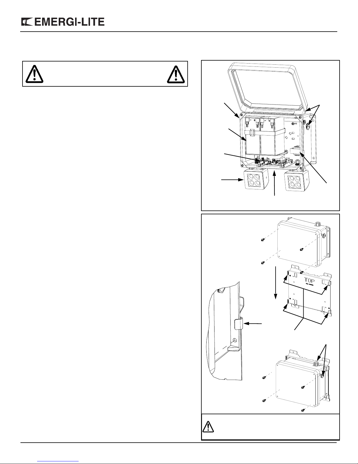
2. Open the cover (See figure 1).
3. For units with remote emergency lighting: remove the bushing located on
the side of the unit and install the conduit fitting rated for Class 1 Div 2
(provided) into the open hole for DC wires.
Wall mount
Install the unit on the wall with 4 screws (not included).
Column mount (option)
a. The universal mounting bracket is an accessory ordered separately
(See figure 2).
b. The bracket can be installed using steel banding for routing around
the column. Standard banding (not provided) must be maximum 3/4-
inch in width. The bracket can also be mounted on a Superstrut®
metal framing (1 5/8-in channel series) using 1/4-in bolts (not
provided). Holes are placed at 9-in apart horizontally.
c. Install the bracket, observing the indicator: TOP.
d. Slide the unit into the tabs located on both sides of the unit until it sits
on the bottom lip of the bracket (See figure 2).
e. Screw the unit onto the bracket with the 4 screws, washers and nuts
included in the bracket kit.
4. A pre-installed conduit fitting rated for Class 1 Div 2 is located on the top
of the unit.
WARNING:
Risk of Electrical Shock.
Disconnect Power before Installation.
Figure 1
Lamps
Battery(ies)
Charger
Housing
Transformer
Conduit
entries(2)
module
Infrared test switch
Pilot light and
Figure 2
Slide housing into
mounting bracket.
Ensure housing
is aligned with
and slide down.
Screw the unit to the
mounting bracket.
Couduit
entries(2)
the tabs
WARNING: THE COLUMN MUST BE
ANCHORED TO THE FLOOR
AND CEILING.

®
HP Series Battery Unit for hazardous locations
2/4
Emergi-Lite® Tel: (888) 552-6467 Fax: (800) 316-4515 www.emergi-lite.com 11/17 750.0020 Rev. A
5. Route the wires from the wire conduit(s) through the conduit fitting(s) and
into the housing.
6. Thread the wire conduit tightly into the conduit fitting ensuring a water-
tight seal. If necessary, seal with silicone or equivalent caulking (not
provided) to prevent water from leaking into the cabinet.
7. Connect AC wires from building utility: install the ground wire.
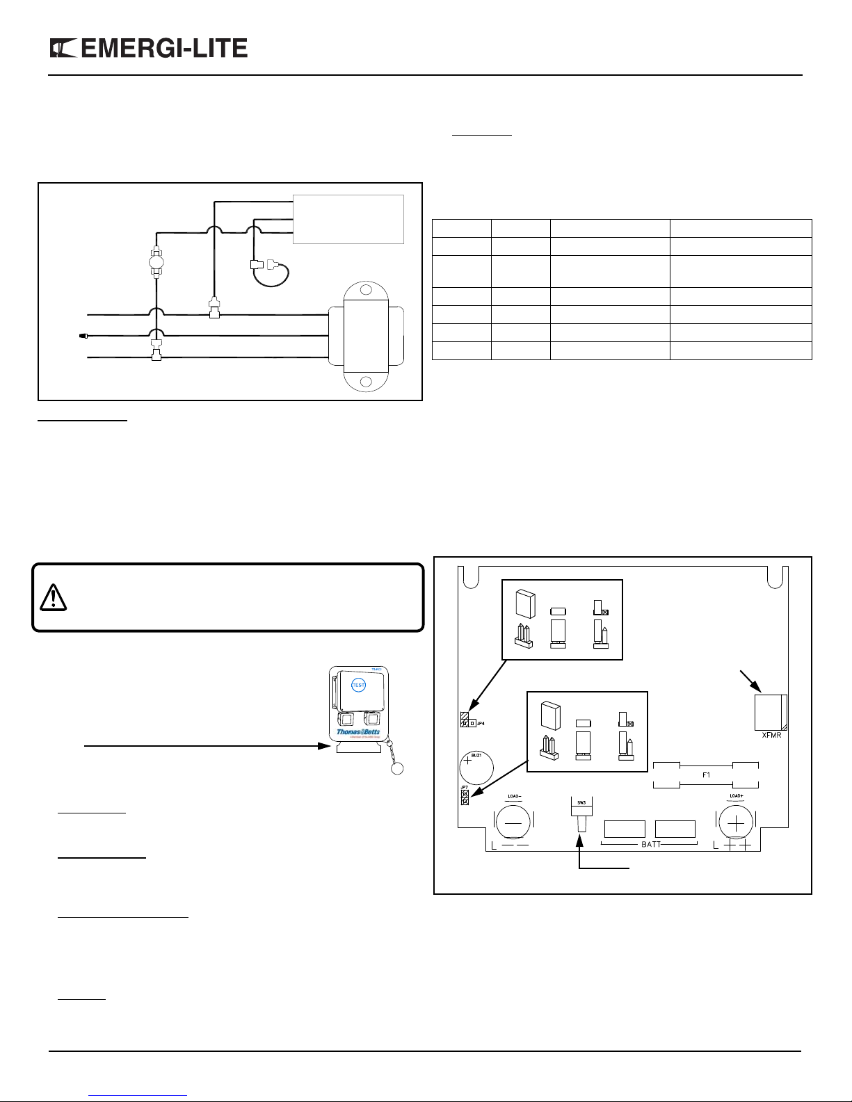
a. Standard unit: connect the transformer primary wires to the utility:
white wire to neutral; black (120Vac) or orange (277Vac) to line
voltage (See figure 3).
Remote emergency lighting (option): connect the remote DC wires to the
terminals of lamp circuit (Figure 3).
b. RFI (option): Connect output line (black) from RFI filter to the
transformer primary: black (120Vac) or orange (277Vac). Connect
RFI filter module to the utility: white wire to neutral, black wire (120/
277Vac) to line (See figure 4).
Option cold-weather: An electric heater and a thermostat are used to control
the ambient temperature inside the equipment.
Connections for 120Vac line voltage (Figure 5):
a. Install three red clips (provided) one on the yellow wire (heater), and
white and black wires (transformer).
b. Connect white wire (heater) to clip of yellow wire (heater).
c. Connect red wire (heater) to clip of white wire (transformer).
d. Connect red wire (thermostat) to clip of black wire (transformer).
WARNING: FAILURE TO ENSURE A WATER-TIGHT
INSTALLATION OF THE CONDUIT AND
FITTING(S) WILL VOID THE MANUFACTURER
WARRANTY.
WARNING: LED EMERGENCY LIGHTS HAVE POLARIZED
WIRES: OBSERVE POLARITY L+ AND L– FOR
LOAD CONNECTION.
Black(120Vac)
White(netural)
Red DC+
Blue DC-
DC wires
for remotes
}
Figure 3
Orange(277Vac)
Green(ground)
Black(line)
120/277Vac
RFI
Black(load)
Connected
to PCBA
White(Netural)
White
White
Orange Black
277Vac 120Vac
(Netural)
(Netural)
Input
{
Figure 4
Transformer
White(Netural)
Black(120V)
Orange(277V)
Red
Yellow Heater Pad
Transformer
Red
White
Figure 5
Thermostat
Maximum mounting height
as per UL924 standards.
LED Lamp wattage Maximum mounting height
6 - Watts 30 Feet
10 - Watts 50 Feet
15 - Watts 60 Feet
®
HP Series Battery Unit for hazardous locations
3/4
Emergi-Lite® Tel: (888) 552-6467 Fax: (800) 316-4515 www.emergi-lite.com 11/17 750.0020 Rev. A
Connections for 277Vac line voltage (Figure 6):
a. Install three red clips (provided) one on the red wire (heater),
and white and orange wires (transformer).
b. Self-connect red wire (heater) on its own clip (electrical cap).
c. Connect white wire (heater) to clip of white wire (transformer).
d. Connect red wire (thermostat) to clip of orange wire
(transformer).
NEXUS (option): refer to page 4 for electrical connections and
commissioning.
8. Install the batteries (if shipped separately) and connect the battery
wires to the charger board. Each battery has its own cable and
must be connected to the charger.
9. Tighten the batteries and cables with the flexible Velcro strap.
10. For vertical pole mount: in addition to the Velcro strap, install the
metal strap and screws provided in the installation kit (Fig 1.) to
hold the battery(ies).
11. Close the cover and tighten the screws.
12. Turn on AC power.
Manual Testing
The equipment comes standard with a one-
button infrared remote control.
Before starting manual testing remove plastic
tab from battery compartment on remote
control.
To initiate a test: orient the remote control
towards the pilot light of the unit and press the
TEST button.
13. Test function (power on, stand-by): press the TEST button, the unit
will start a one-minute test. Pressing the button again will abort the
test in progress.
14. Load disconnect: this option can be used during a power failure to
save battery power during daylight hours. Press the TEST button,
the emergency lights will turn off. By pressing the test button again
the emergency lights will turn back on.
15. On-charger manual test: the unit also has a test button installed on
the charger module located on the bottom of the unit (See figure 7).
This is useful during maintenance, with the unit door open. The
button performs the same functions as the remote control.
Automatic self-test and diagnostic (Option)
16. Self-test: Once power is supplied to the unit it will automatically
initiate a routine self-test calendar as follows:
a. Verifies battery connection, battery failure, charger board failure
and lamps failure.
b. Executes one-minute monthly self-test
c. Executes a 30-minute self-test every 6th month
d. Executes a 90-minute self-test every 12th month
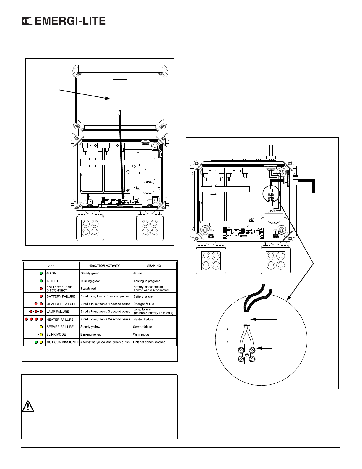
17. Diagnostic: The unit is equipped with a bi-color LED pilot light and
indicates the following status:
a. Green color: AC-on / self-test
b. Red color: Service alarm
A diagnostic label is placed on the unit cover.
Transfer time delay (Option)
This feature works when the AC power is restored: it keeps the
emergency lights "on" for a period of: 5, 10 or 15 minutes (factory set).
If the battery depletes before the end of the time delay, the lamps turn
off and the unit goes in stand-by mode.
The Time Delay feature can be enabled or disabled in the field with the
following procedure (See figure 7):
a. Make sure that the battery and the AC main power are both
disconnected.
b. Disconnect the jumper JP4 to activate the Time Delay
c. Continue with the standard installation
Audible service alarm (Option)
This function acts in case of a Service alarm by generating a beep
every two seconds.
During a service alarm the beep can be silenced by pressing the
remote control test switch.
The audible service alarm can also be permanently disabled in the field
by disconnecting the jumper JP7 (See figure 7).
WARNING: SCREWS MUST BE TORQUED TO AT
LEAST 12INLB TO ENSURE A WATER-
TIGHT SEAL BETWEEN THE COVER AND
HOUSING.
Heater Pad
Transformer
Yellow
White(Netural)
Black(120V)
Orange(277V)
Red
White
Figure 6
Red
Thermostat
O Green Steady AC On
O Green Blinking Testing Mode
O Red Steady On Battery disconnect or
Lamp disconnect
O Red One Blink Battery Failure
OO Red Two Blinks Charger Failure
OOO Red Three Blinks Lamp Failure
OOOO Red Four Blinks Heater Failure
LoadFuse
Low‐voltage
transformer
secondary
Testswitch
BuzzerSilent
NoTD
TD
“ON”
enabled
Battery
Figure 7 Charger module
JP7
JP4
On‐chargertestswitch
®
HP Series Battery Unit for hazardous locations
4/4
Emergi-Lite® Tel: (888) 552-6467 Fax: (800) 316-4515 www.emergi-lite.com 11/17 750.0020 Rev. A
NEXUS (Option)
a. NEXUS wireless (-NEXRF): the equipment has the antenna
installed inside the housing (Figure 8).
Status LED
b. NEXUS wired (-NEX): remove the bushing located on the
side of the unit and install the conduit fitting rated for Class 1
Div2 (provided) into the open hole. Thread the Nexus data
cable conduit tightly into the conduit fitting ensuring a water-
tight seal. If necessary, seal with silicone or equivalent
caulking (not provided) to prevent water leaking into the
cabinet. Route the Nexus data cables into the unit through
the conduit and hub and strip 1in(25mm) of the double
insulation (see detail in figure 9). The two cables are identical
and both contain 2 wires of different colors: color A and color
B. Gather the color A wire from each cable, and connect them
to the same pole on the terminal block. Gather the color B
wire from each cable, and connect them to the other pole on
the terminal block. The result must be 2 wires of the same
color in each pole on the terminal block (see details in figure
9).
Maintenance
None required. If the AC power to the unit is to be disconnected for
two months more: the battery must be disconnected.
Warranty: For the complete warranty information, please refer to
the landing page of our website (http://www.emergi-lite.com/usa/).
WARNING:
This device complies with Part 15 of the
FCC Rules. Operation is subject to the
following two conditions:
1. this device may not cause harmful
interference.
2. this device must accept any
interference received, including
interference that may cause
undesired operation.
Figure 8
RF Antenna
Take care when
opening the cover,
tension may be
placed on the RF
antenna wire and it
could disconnect
from the charger
board.
AC wire entry
Nexus
data cable
Nexus data cable
Tape
Approx.
1in(25mm)
Nexus 2-way
terminal block
Detail
Figure 9
Table of contents


