655 and 655R Actuators
Instruction Manual
Form 1292
July 2007
10
16. To start up and adjust the actuator, follow the
procedures outlined in the Startup section of this
instruction manual.
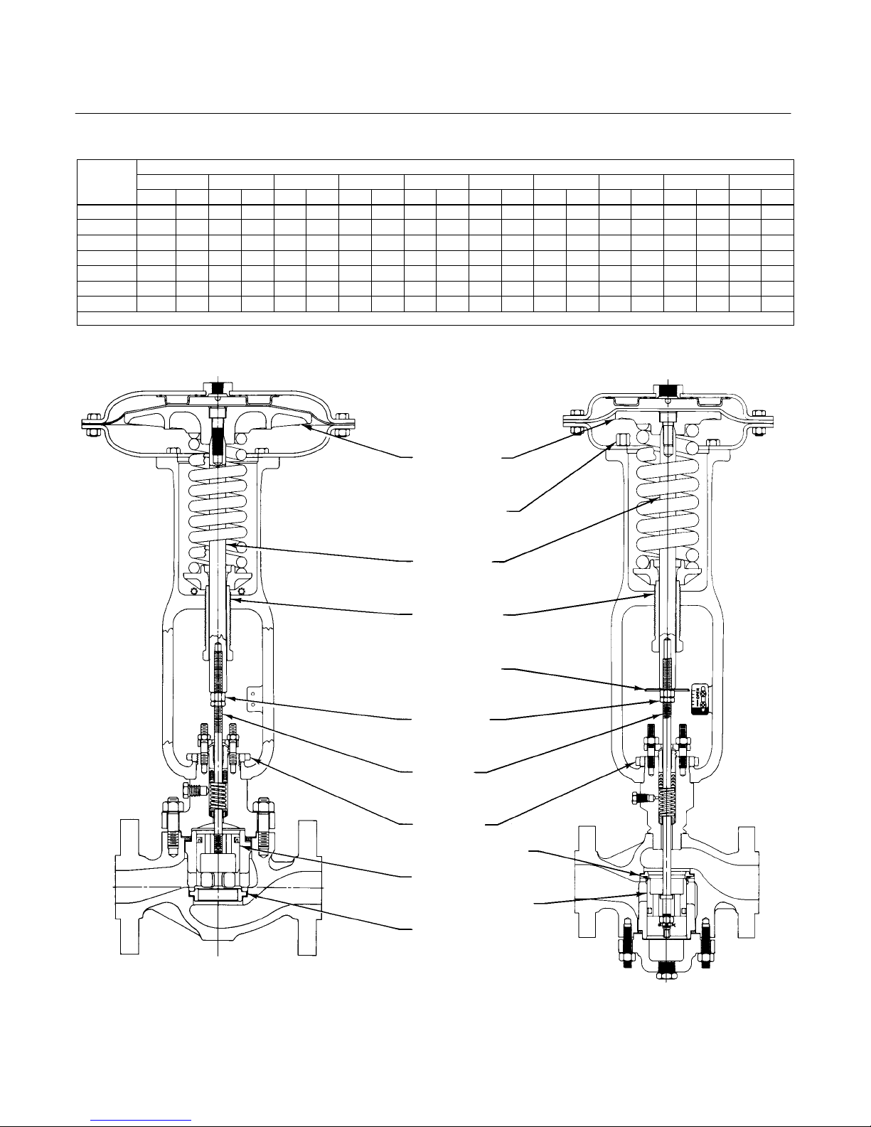
Top-Mounted Handwheel
Top-mounted handwheel assemblies (figures 5, 6
and 7) are normally used as adjustable travel stops
to limit full upward travel of the actuator stem.
Turning the handwheel clockwise forces the actuator
stem downward, while turning the handwheel
counterclockwise allows the spring to force the
actuator stem upward. If the actuator is used with a
push-down-to-close valve, full opening of the valve
plug can be restricted through the appropriate
positioning of the top-mounted handwheel. If the
actuator is used with a push-down-to-open valve,
closing of the valve plug can be restricted by using
the handwheel. A locknut (key 27, figures 5 and 6;
key 137, figure 7) is used to hold the handwheel in
position.
Instructions are given below for complete
disassembly and assembly. Perform the
disassembly only as necessary to accomplish the
required maintenance; then, begin the assembly at
the appropriate step.
Key numbers refer to figure 5 for size 3A and 4A,
figure 6 for size 3B and 4B, and figure 7 for size 32
through 46 top-mounted handwheel assemblies.
Disassembly
1. Bypass the control valve. Relieve all loading
pressure, and remove the tubing or pipe from the
handwheel body.
2. Loosen the hex nut (key 27, figures 5 and 6;
key 137, figure 7). Turn the adjusting screw (key 10,
figure 4) and the handwheel (key 25, figures 5 and 6;
key 51, figure 7) counterclockwise to relieve all
compression.
3. For size 3A and 4A actuators, remove the cap
screws (key 19, figure 4), and lift the handwheel
body (key 28, figure 5) off the actuator.
4. For size 3B through 46 actuators, remove the cap
screws and hex nuts (keys 19 and 20, figure 4), and
then lift off the upper diaphragm casing (key 1,
figure 4) and handwheel assembly. To replace the
O-ring (key 139, figure 7) or for ease of handling,
separate the handwheel assembly from the upper
diaphragm casing. This can be accomplished by
removing the cap screws that secure the handwheel
assembly to the upper diaphragm casing (key 33,
figure 6; key 141, figure 7).
5. Turn the handwheel clockwise two or three turns.
Remove the hex nut (key 22, figures 5 and 6;
key 54, figure 7) and washer (key 24, figures 5
and 6; key 134, figure 7), and lift off the handwheel.
6. Unscrew the locknut (key 27, figures 5 and 6;
key 137, figure 7) from the handwheel stem (key 26,
figures 5 and 6; key 133, figure 7), and then remove
the handwheel stem through the bottom of the
handwheel body (key 28, figures 5 and 6; key 142,
figure 7). A screwdriver slot in the top of the
handwheel stem is provided for this purpose.
7. Check the O-ring (key 29, figures 5 and 6;
key 138, figure 7), and replace it if necessary.
8. To complete disassembly, drive out the groove
pin (key 31, not shown; key 140, figure 7), and slide
the pusher plate (key 32, figures 5 and 6; key 135,
figure 7) off the handwheel stem. For Type 655,
size 3B and 4B actuators, a travel stop (key 34,
figure 6) should also be removed with these parts.
Assembly
This procedure assumes that the handwheel
assembly is completely disassembled. If it is not,
start the instructions at the appropriate step.
1. During assembly, apply lithium grease lubricant
(key 241) to the handwheel stem and threads, the
pusher, and to the O-rings as shown in figures 5, 6
and 7.
2. Slide the pusher plate (key 32, figures 5 and 6;
key 135, figure 7) onto the handwheel stem, and, if
necessary, insert the groove pin (key 31, not shown;
key 140, figure 7). For Type 655, size 3B and 4B
actuators, a travel stop (key 34, figure 6) should also
be inserted on the handwheel stem with these parts.
3. Insert the handwheel stem into the handwheel
body (key 28, figures 5 and 6; key 142, figure 7);
then, screw the hex nut (key 27, figures 5 and 6;
key 137, figure 7) onto the handwheel stem.
4. Install the handwheel (key 25, figures 5 and 6;
key 51, figure 7) and washer (key 24, figures 5
and 6; key 134, figure 7) onto the handwheel stem,
and secure it with the hex nut (key 22, figures 5
and 6; key 54, figure 7).
5. For size 3A and 4A actuators, set the
handwheel body onto the actuator, and secure it with
the cap screws (key 19, figure 4).
Note
When you replace actuator
diaphragms in the field, take care to
ensure the diaphragm casing bolts are