EMIX EMRM-810 User manual
1
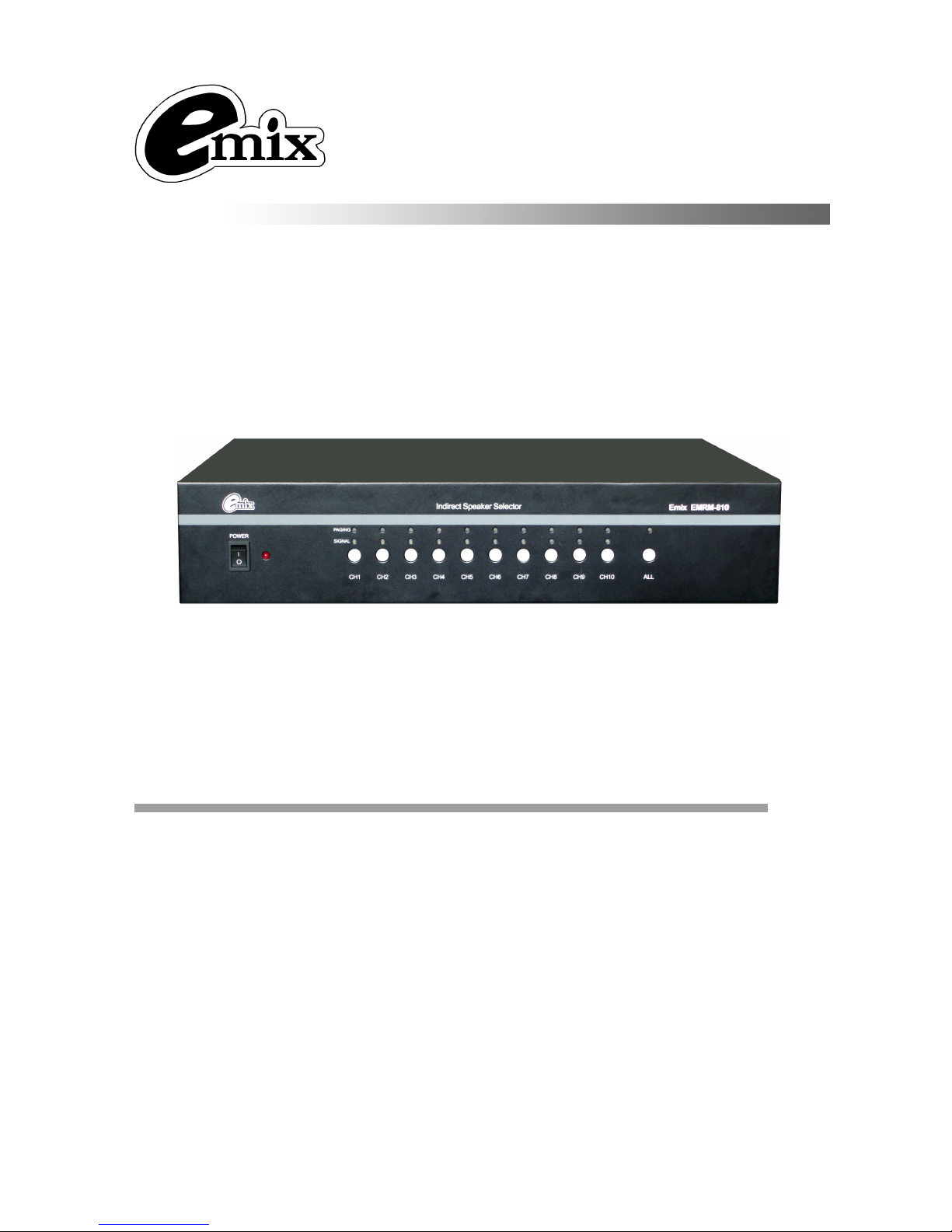
EMRM-810
Indirect Speaker Selector
Professional distributor for paging.
10 inputs.
10 paging channels.
10 outputs.
10 EMRM-810 can be linked at most, they can be recognized bye binary code.
4 paging microphones with 4 classes priority as MIC1>MIC2>MIC3>MIC4.
+24V DC power supply.
OW
N
E
R
’
S
M
ANUA
L
B
e
f
o
re
op
e
ra
ti
ng
,
p
l
e
a
s
e
r
e
ad
t
h
i
s
m
a
nu
al
c
o
m
p
l
e
t
e
l
y.
FEATURES:
Professional Public Address System

2
1. MIC inputs
:
4pcs of EMRM-800 can be connected.
2
.
COM of outputs, connecting to the COM of speaker.
3
.
Audio outputs, connecting to the HOT of speaker.
4
.
+24V DC power supply.
5
.
AC power supply.
6
.
Data communication:
FRONT PANEL:
1. AC power switch
2. Power Indicator Light (LED is bright when press Power Switch)
3. PAGING indicator( inputs active)
4. SIGNAL
indicator ( output active)
5. CH1-10 Channel Select Key
6. All call button
7. All call indicator
REAR PANEL AND CONNECTIONS:
1 2 3
4
5 6
7
1 2
3 4
5
6 7
8
9 10
11
12
13
14

3
7
.
+24V DC serial output: total power should be less than 20W.
8
.
Address setting: binary code for recognizing 10 units of EMRM-810.
9
.
Audio output : to pre. amplifier or amplifier
10
.
COM terminal of BGM input, connecting to the COM of amplifier.
11
.
HOT terminal of BGM input, connecting to the HOT of amplifier.
12
.
HOT terminal of audio input, connecting to the HOT of paging amplifier.
13
.
COM terminal of audio input, connecting to the COM of paging amplifier.
14
.
AC FUSE.
CONNECTION:
NOTE
:
EMRM-810 will be uploaded to the state for the four paging (EMRM-800)
,
the only state in the 1
st
paging-on instructions, the other three paging refused to EMRM-810 state impact
。
10 channel B
1
-
10 zone
10 channel A
1 channel A
1 channel B
EMRM-800
(
priority 1
)
EMRM-800
(
priority 4
)
EMRM-800
(
priority 3
)
+24
VDC
BGM amplifier
Paging amplifier
EMRM-800
(
priority 2
)
LINK EMRM-810
DC24V

Operation:
1.
..
.Address setting:
For dividing 10 units of EMRM-810, we design 6 address codes on the rear panel and recognize
them bye binary system. Please refer to the pictures below: There are 3 pins in each address code,
it means “1” of binary system while the upper two pins are connected together; it means “0” of binary
system while the nether two pins connoted together (Per fig.1). Please note that address code of 1
st
EMRM-810 is 000000 ( Per fig.2). The address code of 2
nd
EMRM-810 is 000001( Per fig.3). Please
refer to the setting method of these two equipments while setting other EMRM-810 equipments. You
can also refer to the “Address setting and binary code table”.
Address setting and binary code table
EMRM-810 Address code EMRM-810 Address code
No.1 000000 No.6 000101
No.2 000001 No.7 000110
No.3 000010 No.8 000111
No.4 000011 No.9 001000
No.5 000100 No.10 001001
A
L
A
RM
I
N
P
U
T (
connect
with Fire Center)
1
2
3
4
5
6
7
8
9
10
11
12
13
1
-
10
: +24V DC outputs
11-25: COM
14
1
5
,
1
6
,
17
18
1
9
,
20
2
1
,
22
23
,
24
,
25
1
0
(fig.1)
0
0
0
0
0
0
( fig.2)
0
0
0
0
0
( fig.3)
1

5
2.
..
.Operation of the CH1-10 select key:
The “PAGING” indicator LED is bright when you pressed the channel select key. The
equipment will send out the paging signal which comes from the paging microphone, this
namely the zone is under PAGING state. By contraries, the output indicator “SIGNAL” is off
when there is not output signal. Pressing the select key again, the “PAGING” LED will be off,
the BGM signal will be sent out again, that means the equipment is sending out the back
ground music.
Press down the “ALL” key, the whole system and the LED indicator will be actived, the
equipment is under all call paging state. It will return to BGM state if you press the “ALL” key
again.24V output from the relative feet of the 25-pin plugs.
There are 4 at the most paging microphone can be connected on the rear panel, only ONE
paging microphone can page at the same time. The priority class is :
MIC1>MIC2>MIC3>MIC4. When the higher priority microphone is paging, the lower priority
microphone can not page and the MIC indicator LED will wink.
MRM810 will send the unfold or closed signal to the paging selector in working estate, the
signal will be sent to the 1
st
paging selector when 4 paging selectors are not in working
estate.
SPECIFICATION:
No. of Channel 10
Input capacity 70-100V, 10A
Output capacity 70-100V, 5A
Alarm Signal 5V-24V, 0V
(
short circuit
)
Protection AC fuse
×
1
Power Source AC 240V/50Hz
Spare Power DC24V
(
each ouputs should be <2W in 10 ouputs
)
Dimensions 485
×
88
×
345mm
Gross weight 7.2kg
Net weight 5.6kg
CAUTION
For safety, please pull out power cord from socket when “Power switch” is off if
the equipment is not used. Please keep the equipment out of water.
To reduce the risk of electric shock, do not remove the cover.
P
l
ea
s
e
c
o
n
t
ac
t
us or
a
ut
h
or
i
ze
d
d
ea
l
e
r
s
f
or
r
e
p
a
i
r
s
tu
ff.
Table of contents


