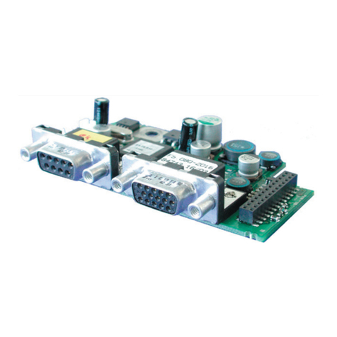
KEBCO COMBIVERT F5 User manual

COMBIVERT
Mat.No. Rev.
DSF5ZEM-K002 1A
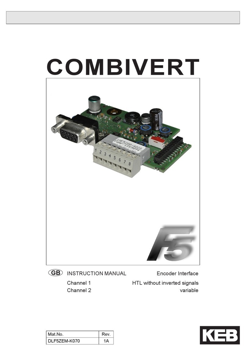
GB INSTRUCTION MANUAL Encoder interface
Channel 1
Channel 2
variable
SSI


3
Table of Contents
Inhaltsverzeichnis
1. Preface............................................................................................................. 4
1.1 Information on special measures.......................................................................................4
1.2 Documentation.....................................................................................................................4
1.3 Validity and liability .............................................................................................................5
1.4 Copyright..............................................................................................................................6
1.5 SpeciedApplication ..........................................................................................................6
2. Product description........................................................................................ 7
2.1 General .................................................................................................................................7
2.2 Material number ...................................................................................................................7
2.3 Scope of delivery (option or replacement delivery) .........................................................8
2.4 Mechanical Installation .......................................................................................................8
3. Description of the Interface ........................................................................... 9
3.1 Voltage supply .....................................................................................................................9
3.2 Channel 1..............................................................................................................................9
3.3 Channel 2..............................................................................................................................9
3.4 Specicationchannel2.......................................................................................................9
3.4.1 Description of socket X3B....................................................................................................10
3.4.2 Input signals channel 2 ........................................................................................................10
3.4.2.1 Serial data transmission ......................................................................................................10
3.4.2.2 Encoder breakage recognition............................................................................................. 11
3.4.3 Connection of the encoder...................................................................................................12
3.4.4 Encoder cable......................................................................................................................13
3.4.5 Encoder line length ..............................................................................................................14
3.5 Start-up ...............................................................................................................................14
3.6 Error messages..................................................................................................................14
Listofgures
Figure 1: SSI - Encoder interface at channel 2 ........................................................................7
Figure 2: Voltage supply of control and encoder interfaces .....................................................9
Figure 3: Socket X3B .............................................................................................................10
Figure 4: Serial data transmission with SSI encoder ............................................................. 11
Figure 5: Connection example: Encoder with 18V supply (e.g. Sick-Stegmann AG615).......12
Figure 6: Connection example: Encoder with 5V supply (e.g. Kübler 9081)..........................13
4
Preface
1. Preface
The described hard- and software are developments of the Karl E. Brinkmann GmbH. The
enclosed documents correspond to conditions valid at printing. Misprint, mistakes and tech-
nical changes reserved.
1.1 Information on special measures
The used pictograms have following signicance:
Danger Is used, when death or serious bodily injury may be the consequence
of non-observance of the measure.
Warning Is used, when bodily injury and/or substantial property damage may
be the consequence of non-observance of the measure.
Caution Is used, when property damage may be the consequence of non-ob-
servance of the measure.
Attention Is used, when noise sensitive or unrequested operation may be the
consequence of non-observance of the measure.
Info Is used, when a better or simpler result can be the consequence of the
measure.
For a special case the instructions can be supplemented by additional pictograms and text.
1.2 Documentation
Attention Documentation via www.keb.de
Prior to performing any work on the unit, it is absolutely necessary to down-
load and read the documentation, especially the safety precautions and in-
structions for use. Follow these steps to get the documentation:
Step 1 Read the material number (Mat.No.) from nameplate
Step 2
Input the material number at "www.keb.de => Service => Downloads" and
click "search".
Downloads
Search for specific material numbers
Please enter a comlete (11-digit) material number.
Search for:
search
15G6DCD-3510
further on next side

5
Preface
Step 3
The entire documentation associated with the device will be displayed, in-
cluding the instruction manuals in German and English. If available, other
translations are also indicated. Make sure that the user understands the pro-
vided language.
Should you be unable to read or understand the documentation, do not
take any further steps. Please inform our support network for further
assistance.
Non-observance of the safety and operating instructions leads to the loss of any liability
claims. The warnings and safety instructions in this manual work only supplementary. This
list is not exhaustive.
1.3 Validity and liability
The use of our units in the target products is beyond of our control and therefore exclu-
sively the responsibility of the machine manufacturer, system integrator or customer.
The information contained in the technical documentation, as well as any user-specic advice
in spoken and written and through tests, are made to best of our knowledge and information
about the application. However, they are considered for information only without responsibil-
ity. This also applies to any violation of industrial property rights of a third-party.
Selection of our units in view of their suitability for the intended use must be done generally
by the user.
Tests can only be done within the application by the machine manufacturer. They must
be repeated, even if only parts of hardware, software or the unit adjustment are mod-
ied.
Danger by tamper from unauthorized personnel
Unauthorised opening and tampering may lead to death, bodily injury, prop-
erty damage and malfunctions. Modication or repair is permitted only by
KEB authorized personnel. Infringement will annul the liability for resulting
consequences.
The suspension of liability is also valid especially for operation interruption damages, loss of
prot, data loss or other damages. The disclaimer will void the warranty. This is also valid, if
we referred rst to the possibility of such damages.
If individual regulations should be futile, not effective or impracticable, then the effectivity of
all other regulations or agreements is not affected by this.
Through multitude applications not each possible case of installation, operation or mainte-
nance can be considered. If you require further information or if special problems arise which
are not treated in detail in the documentation, you can request the required information from
the local agency of the company Karl E.Brinkmann GmbH.

6
Preface
1.4 Copyright
The customer may use the instruction manual as well as further documents or parts from it for
internal purposes. Copyrights are with KEB and remain valid in its entirety.
KEB®, COMBIVERT®, COMBICONTROL®and COMBIVIS®are registered trademarks of Karl
E. Brinkmann GmbH.
Other wordmarks or/and logos are trademarks (™) or registered trademarks (®) of their re-
spective owners and are listed in the footnote on the rst occurrence.
When creating our documents we pay attention with the utmost care to the rights of third
parties. Should we have not marked a trademark or breach a copyright, please inform us in
order to have the possibility of remedy.
1.5 SpeciedApplication
The used semiconductors and components of the Karl E.Brinkmann GmbH are developed
and dimensioned for the use in industrial products. If the KEB COMBIVERT F5 is used in
machines, which work under exceptional conditions or if essential functions, life-supporting
measures or an extraordinary safety step must be fullled, the necessary reliability and secu-
rity must be ensured by the machine builder.
The operation of our products outside the indicated limit values of the technical data leads to
the loss of any liability claims.
The safety function is limited to a service life of 20 years. After this time the unit must be re-
placed.

7
Product description
2. Product description
X3B X3A
Channel 2 Channel 1
SSI variable
Synchronous Serial Interface see material number
Figure 1: SSI - Encoder interface at channel 2
2.1 General
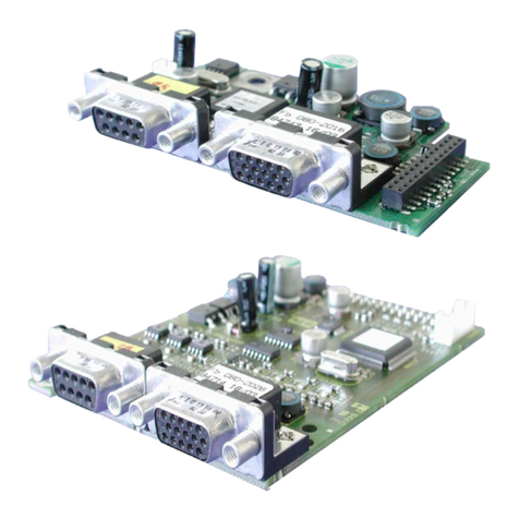
Each of the interface cards delivered by KEB include two interfaces. As there are numerous
different combinations available each interface will be described by means of separate in-
structions. The instruction comprises the installation of the interface card, the connection as
well as the start-up of a suitable encoder. Further information and the parameter adjustments
are described in the application manual for the inverter/servo.
2.2 Material number
xM F5 K8x x x x x
Term of delivery 0 installed Z Option, spare part
1 SIN/COS 5 Resolver
3 Endat LHTL input without
inverse signal
4 TTL input
F5 Series
applicable for housing size 1M D, E (PCB 1M.F5.280-1015/ -0025/ -4017/
-2020/ -2021)
2M G…U (PCB 2M.F5.280-1015/ -2020/ -2021)

8
Product description
2.3 Scope of delivery (option or replacement delivery)
• Encoder interface
• two instruction manuals
• xing bolt
• packing material
2.4 Mechanical Installation
All kind of works on the inverter may be carried out by authorized personnel in accordance
with the EMC and safety rules only.
• Switch inverter de-energized and await capacitor discharge time
• Pull off operator
• Remove plastic cover
•Remove xing bolt
• Fix interface board beginning from the socket connector straightly
•Screw in xing bolt
• Attach plastic cover

9
Description of the Interface
3. Description of the Interface
3.1 Voltage supply
Uint 24 VDC Internal voltage supply of COMBIVERT.
X2A
X3A
X3B
5,2V
24V
5V
24V
5V
Uint
Uext
Iint
120 mA at Hiperface, Sin/Cos, EnDat and SSI-Sin/
Cos.
170 mA at all other encoder interfaces.
Uext Control terminal strip (X2A) of the COMBIVERT with
external voltage supply 24…30 DCV.
24 V Voltage output of encoder interfaces X3A and X3B for
encoder supply.
I24V
Current Iint reduces itself by draw current to the 5 V output
in accordance with the following formula:
5,2 V x I5V
I24V = Iint - –––––––––
Uint
5 V Voltage output for encoder supply. 5.2 V are obtained
from the 24 V voltage.
I5V
300 mA at Hiperface, Sin/Cos, EnDat and SSI-Sin/
Cos.
500 mA at all other encoder interfaces.
1A at external supply (dependent on the voltage
source)
Figure 2: Voltage supply of control and encoder interfaces
3.2 Channel 1
The description of input X3A is depending on the used encoder interface. It is described in a
separate manual.
3.3 Channel 2
3.4 Specicationchannel2
Socket X3B SUB-D9
Interface type SSI (synchronous serial interface)
Input signals 5 V TTL according to RS485
Outputs and inputs Clock+, Clock-, Data+, Data-
Code Binary coded, Gray Code
Resolution 12 Bit Singleturn, 12 Bit Multiturn
Limiting frequency 220 kHz
increments per revolution 1…16383 inc (recommendation 2500 inc for speed upto
4500 rpm
Input resistance 150 Ω
Max. line length 50 m, the value is additionally limited by the signal fre-
quency, cable capacity and supply voltage.

10
Description of the Interface
3.4.1 Description of socket X3B
54321
9876
PIN Name Description
1 CL+ Output of the clock signal
2 DAT+ Input data track
3 – –
45 V Voltage output 5 V
524 V Voltage output 20…30 V
6 CL- Difference signal to clock signal C+
7DAT- Difference signal to data track DAT+
8 – –
9 COM Reference potential for voltage supply
– GND Connection for shield at connector housing - is directly connected with
the inverter earth.
Figure 3: Socket X3B
3.4.2 Input signals channel 2
3.4.2.1 Serial data transmission
Singleturn absolute encoder divide one revolution of the shaft into a dened number of meas-
uring steps. This are 4096 positions at a SSI protocol, corresponding to a resolution of 12Bit.
Multiturn absolute encoder do not only detect angle positions within one revolution but also
the number of revolutions. With a resolution of the multiturn part of 12 Bit this corresponds to
4096 revolutions. The position measuring area of 0…224-1 should not be left, since an over-
ow and/or underow is not evaluated as error. A system offset can be dened by writing on
Ec.34 or approaching to reference point.

11
Description of the Interface
Clock signal
Data
Monoop
Position data
P: Parallel position data
T: Period
Tp: Clock interruption up to the next request
tm: Pulse duration of the monoop
tv: Deceleration time
Dhigh:Most signicant position bit
Dlow:Least signicant position bit
Figure 4: Serial data transmission with SSI encoder
3.4.2.2 Encoder breakage recognition
An error bit is evaluated for monitoring of the encoder at channel 2. The monitoring is switched
on/off with parameter Ec.42 (Ec.20 up to V2.8). The encoder breakage recognition triggers an
„error! encoder 2“ (value 34).
For encoder breakage detection the encoder needs to send a so-called Power failure bit and
the evaluation with Ec24 "SSI power failure bit" has to be enabled.

12
Description of the Interface
3.4.3 Connection of the encoder
• Encoder cable double-shielded and twisted in pairs
• Connect exterior shielding at both ends to PE/GND
• Connect interior shielding at one side to COM
• Do not connect exterior and interior shielding
Two connection examples of SSI encoders are following. The assignment of the motor en-
coder interface is different according to the manufacturer. The examples must be adopted
accordingly.
Encoder plug Socket X3B
54321
9876
Name PIN Material number: 00F4609-xxxx PIN Core color
GND – – exterior shielding
CL+ 3 1 green
CL- 11 6 yellow
Data+ 2 2 blue
Data- 10 7 red
COM 1 9 white + internal shielding
24 V 8 5 brown
Figure 5: Connection example: Encoder with 18V supply (e.g. Sick-Stegmann AG615)

13
Description of the Interface
Encoder plug Socket X3B
54321
9876
Name PIN Material number: 00F4909-xxxx PIN Core color
GND – – Solder external shielding to
metal housing
CL+ 3 1 green
CL- 4 6 yellow
Data+ 5 2 blue
Data- 6 7 red
COM 1 9 white + internal shielding
5 V 2 4 brown
Figure 6: Connection example: Encoder with 5V supply (e.g. Kübler 9081)
3.4.4 Encoder cable
KEB delivers ready-made encoder cable in accordance with the following number code:
For Stegmann encoder:
00F4609-xPxx x,xx m z.B. 00F4609-0P60 corresponds to 0,60 m
00F4609-0xxx xxx m z.B. 00F4609-0040 corresponds to 40 m
For Kübler encoder:
00F4909-xPxx x,xx m z.B. 00F4909-0P60 corresponds to 0,60 m
00F4909-0xxx xxx m z.B. 00F4909-0040 corresponds to 40 m
KEB encoder cables are corresponding to the following specication:
Signal lines 3 x (2 x 0.14 mm²)
Supply lines 2 x 0.5 mm²
Particularities trailing capable, oil resistant
Temperature range constant up to 80 °C
Color green RAL 6018

14
Description of the Interface
3.4.5 Encoder line length
The maximum line length for the connection line is limited by the signal frequency, cable ca-
pacity and the line resistance.
Encoder line length = U - Umin
––––––––––
Imax • 2 • R
max. encoder current Imax: see encoder description
Supply voltage U: Voltage output
min. supply voltage Umin: see encoder description
KEB encoder cable resistance R: 0.036 Ω/m at 0.5 mm²
3.5 Start-up
After installation or exchange of an encoder interface some adjustments of the inverter/servo
software have to be done before operation:
• Switch on inverter
• Select application mode
• Select parameter Ec.10 and control whether value „6: SSI“ is entered. The
displayed value has to be conrmed by „ENTER“ in any case.
• Select parameter Ec.11 and adjust the increments per revolution to 1024.
• Select parameter Ec.17 and adjust 4-fold evaluation (1024 inc x 4 = 4096 inc)
• Ec.42 and Ec.24 (Ec.20 upto V2.8) and adjust the encoder breakage recogni-
tion dependent on the case of operation.
• Select parameter Ec.21 and adjust multiturn resolution (standard 12 Bit); ad-
just „0“ for singleturn encoders.
• Select parameter Ec.22 and adjust clock frequency for SSI encoder.
• Select parameter Ec.23 and adjust data format (standard Gray-Code).
• Ec.30 displays the read out position of the SSI encoder.
•A system offset can be dened by writing on parameter Ec.34 or approaching
to reference point.
3.6 Error messages
Error messages and their meaning are described in chapter 9 of the application manual.

15
Notes

KEB Antriebstechnik Austria GmbH
Ritzstraße 8 • A-4614 Marchtrenk
fon: +43 7243 53586-0 • fax: +43 7243 53586-21
net: www.keb.at • mail: [email protected]
KEB Antriebstechnik
Herenveld 2 • B-9500 Geraadsbergen
fon: +32 5443 7860 • fax: +32 5443 7898
mail: [email protected]
KEB Power Transmission Technology (Shanghai) Co.,Ltd.
No. 435 Qianpu Road, Chedun Town, Songjiang District,
CHN-Shanghai 201611, P.R. China
fon: +86 21 37746688 • fax: +86 21 37746600
net: www.keb.de • mail: [email protected]
KEB Antriebstechnik Austria GmbH
Organizační složka
K. Weise 1675/5 • CZ-370 04 České Budějovice
fon: +420 387 699 111 • fax: +420 387 699 119
mail: [email protected]
KEB Antriebstechnik GmbH
Wildbacher Str. 5 • D–08289 Schneeberg
fon: +49 3772 67-0 • fax: +49 3772 67-281
mail: [email protected]
KEB España
C/ Mitjer, Nave 8 - Pol. Ind. LA MASIA
E-08798 Sant Cugat Sesgarrigues (Barcelona)
fon: +34 93 897 0268 • fax: +34 93 899 2035
mail: [email protected]
Société Française KEB
Z.I. de la Croix St. Nicolas • 14, rue Gustave Eiffel
F-94510 LA QUEUE EN BRIE
fon: +33 1 49620101 • fax: +33 1 45767495
net: www.keb.fr • mail: [email protected]
KEB (UK) Ltd.
Morris Close, Park Farm Industrial Estate
GB-Wellingborough, NN8 6 XF
fon: +44 1933 402220 • fax: +44 1933 400724
net: www.keb.co.uk • mail: [email protected]
KEB Italia S.r.l.
Via Newton, 2 • I-20019 Settimo Milanese (Milano)
fon: +39 02 3353531 • fax: +39 02 33500790
net: www.keb.de • mail: [email protected]
KEB Japan Ltd.
15–16, 2–Chome, Takanawa Minato-ku
J-Tokyo 108-0074
fon: +81 33 445-8515 • fax: +81 33 445-8215
mail: [email protected]
KEB Korea Seoul
Room 1709, 415 Missy 2000
725 Su Seo Dong, Gang Nam Gu
ROK-135-757 Seoul/South Korea
fon: +82 2 6253 6771 • fax: +82 2 6253 6770
mail: [email protected]
KEB RUS Ltd.
Lesnaya Str. House 30, Dzerzhinsky (MO)
RUS-140091 Moscow region
fon: +7 495 632 0217 • fax: +7 495 632 0217
net: www.keb.ru • mail: [email protected]
KEB America, Inc.
5100 Valley Industrial Blvd. South
USA-Shakopee, MN 55379
fon: +1 952 224-1400 • fax: +1 952 224-1499
net: www.kebamerica.com • mail: [email protected]
© KEB
Mat.No. DSF5ZEM-K002
Rev. 1A
Date 10/2016
More and latest addresses at http://www.keb.de
KEB Automation KG
Südstraße 38 • D-32683 Barntrup
fon: +49 5263 401-0 • fax: +49 5263 401-116
net: www.keb.de • mail: [email protected]
KEB worldwide…
Other manuals for COMBIVERT F5
48
Table of contents
Other KEBCO Recording Equipment manuals

KEBCO
KEBCO COMBIVERT F5 User manual

KEBCO
KEBCO ACOMBIVERT F5 X3A User manual

KEBCO
KEBCO COMBIVERT F5 User manual

KEBCO
KEBCO F5 Series User manual

KEBCO
KEBCO COMBIVERT F5 User manual

KEBCO
KEBCO COMBIVERT F5 User manual

KEBCO
KEBCO COMBIVERT F5 User manual

KEBCO
KEBCO COMBIVERT F5 User manual

KEBCO
KEBCO COMBIVERT F5 User manual

KEBCO
KEBCO COMBIVERT F5 User manual