EMME M74NB Parts list manual

05/2020
0837_GB_99
High Technology Low Cost
M74NB ·M76NB
M74NBFG ·M76NBFG
M74NBFE ·M76NBFE
M74NBFXE ·M76NBFXE
Instructions for installation,
use e maintenance
GA KITCHEN WITH
PILOT

CHARACTERI TIC
0837_GB_99 - AS KITCHENS WITH PILOT
2· 20
Supplied by:
Date:
Customer Service:
FAX
e-mail

INDEX
0837_GB_99 - AS KITCHENS WITH PILOT
1 Diagram 4
2 Characteristics of the appliances 6
3 Technical data 6
4 Installation instructions 8
4.1 Safety rules 8
4.2 Structure, framework and safety dev ces of the appl ances 8
4.2.1 Cooking zone 8
4.2.2 Oven 8
as version N 2/1 8
Electric version N 2/1 8
Electric version N 1/1 ventilated 8
4.3 Assembly 8
4.3.1 Installation premises 8
4.3.2 Statutory regulations and technical requirements 8
4.3.3 Installation 9
4.3.4 as connection 9
4.3.5 Electrical connection 9
4.3.6 Equipotential 9
5 Operation preparation 9
5.1 Preparat on and Start-up 9
5.1.1 Start-up 9
5.1.2 Check of power 9
5.1.3 Checking the input pressure 9
5.1.4 Power check with volumetric methodo 9
5.1.5 Power check for operation with liquid gas 11
5.1.6 Operation control 11
5.1.7 Check of pilot flame 11
5.1.8 Checking the primary air 11
5.1.9 Operator training 11
5.1.10 Conversion and adjustment 11
5.1.11 Replacement of open flames injectors 11
5.1.12 Replacement of pilot injectors of open flames 11
5.1.13 Setting reduced capacity power 11
5.1.14 Replacement of burner injector of gas oven N 2/1 11
5.1.15 Replacement of pilot injector of gas oven N 2/1 11
5.2 Ma ntenance 11
5.3 Replac ng parts 12
5.3.1 Open flame gas cock 12
5.3.2 Open flame thermocouple 12
5.3.3 as valve gas oven N 2/1 12
5.3.4 Plug gas oven N 2/1 12
5.3.5 Thermocouple gas oven N 2/1 12
5.3.6 Main burner gas oven N 2/1 12
5.3.7 Heating elements of electric oven N 2/1 12
5.3.8 Heating elements of electric oven N 1/1 12
5.3.9 Fan electric oven N 1/1 12
6 Instructions for use 14
6.1 Safety, clean ng and repa r rules 14
6.2 Start-up 14
6.2.1 Lighting and disconnecting flame burner with pilot 14
6.3 L ght ng and shutdown of electr c oven GN 2/1 14
6.4 L ght ng and shutdown of electr c oven GN 1/1 15
6.5 L ght ng and shutdown of gas oven GN 2/1 15
6.5.1 Lighting the pilot gas oven N 2/1 15
6.5.2 Lighting the main burner and temperature adjustment gas
oven N 2/1 15
6.6 Turn ng the appl ance off n case of breakdown 15
6.6.1 What to do in case of failure 15
6.6.2 What to do in case of prolonged period of disuse 15
6.7 Appl ance care and frequency of ma ntenance 15
6.8 Recommendat ons for handl ng “sta nless steel” ndustr al
k tchens 15
6.8.1 Useful information on “stainless steel” 15
6.8.2 Warnings and advice for maintenance of “stainless steel”
appliances 16
6.8.3 WEEE Directive 16
7 Appendix: Electrical diagrams 17-18
3· 20

4· 20
MM
6
7
4
1
5555
7
55 7
8
7
5
5
7
8
7
MM
8
3
5 5
75 5
8
55 55
6
1
4
7
3
3
3
3
E
power
Gas 1/2"
Electric
power
Electric power
Data plate Data plate
Electric power
Data plateData plate
Gas 1/2"
Data plate
Gas 1/2"Gas 1/2"
Gas 1/2" Gas 1/2"
Data plate
1 - DIAGRAM
0837_GB_99 - AS KITCHENS WITH PILOT

5· 20
6
5
4
3
2
1
6
5
4
3
2
1
MM
!
"
#$$
%%%&%
6
'
(
&%&% #) $
*$$
&%&% 9)$
)$$$
)$$$
*
$$
M M
%&% %%
+
6
'
(
!
"
#$$
*$$
#)$&% &%
#9
,&
9)$& % &%
#9
)$$$
*
$$
#9
)$$$
#9
,& ,&
,&
,&
D-.- /0-.2
Gas 1/2"
Data plate Data plate
Data plate
Gas 1/2"
Electric
power
Electric
power
Data plate
Electric power
Data plate
Electric power
Gas 1/2" Gas 1/2"
Gas 1/2"Gas 1/2"
1 - DIAGRAM
0837_GB_99 - AS KITCHENS WITH PILOT

2 - CHARACTERI TIC OF THE APPLIANCE
3 - TECHNICAL DATA
Questi apparecchi sono destinati ad un uso professionale.
L’installazione, la riparazione e l’utilizzo devono essere eseguiti da
personale specializzato.
These instructions for installation are for our gas kitchens set up for
the category in the table 1 on pag. 7. The data plate is located on
the appliance, see diagram. Beware of inexpert handling.
6· 20
Model
M74NB
M76NB
M74NBFG
M76NBFG
M74NBFE
M76NBFE
M74NBFXE
M76NBFXE
Description
Gas range 4 burners with pilot flame - open compartment
Gas range 6 burners with pilot flame - open compartment
Gas range 4 burners with pilot flame - gas oven GN 2/1
Gas range 6 burners with pilot flame - gas oven GN 2/1
Gas range 4 burners with pilot flame - electric oven GN 2/1
Gas range 6 burners with pilot flame - electric oven GN 2/1
Gas range 4 burners with pilot flame - el convection oven GN 1/1
Gas range 6 burners with pilot flame - el convection oven GN 1/1
Dimensions in mm. (LxDxH)
800 x 700 x 900
1000 x 700 x 900
800 x 700 x 900
1000 x 700 x 900
800 x 700 x 900
1000 x 700 x 900
800 x 700 x 900
1000 x 700 x 900
N.
51BS3547
51BS3547
51BS3547
51BS3547
51BS3547
51BS3547
51BS3547
51BS3547
0051
TIPO/TYPE
CAT/KAT GAS/GAZ G30 G31 G20 G25
II2H3B/P P mbar 30 30 20 -
II2H3+ P mbar 30 37 20
-
-
II2H3+ P mbar 28 37 20 -
25II2L3B/P P mbar 30 30
II2ELL3B/P P mbar 50 50 20 20
II2E+3+ P mbar 28 37 20 25
II2H3B/P P mbar 50 50 20 -
I2E P mbar - - 20 -
- -II2H3B/P P mbar 30 30
II2H3+ P mbar 28 37 20 -
- -
- -
I3B/P P mbar 30 30
I3+ P mbar 28 37
SE FI DK CZ SK SI
IT CH PT
ES IE GB GR
NL
DE
FR BE
AT CH
LU
EE LV LT
EE LV LT
NO MT CY IS HU
CY
MOD.
MOD.
ART.
N.
N.
Qn kW
m3/h
MADE IN ITALY
Predisposto a gas: - Gas preset: - Prevu pour gaz:
Eingestelt für Gas: - Preparado para gas: -
Geschuckt voor:
V AC kW Hz
THE APPLIANCE MUST BE CONNECTED IN COMPLIANCE WITH THE LAWS IN FORCE
AND INSTALLED IN A WELL-VENTILATED ROOM. READ THE INSTRUCTION MANUALS
BEFORE INSTALLING AND USING THE APPLIANCE.
THE APPLIANCE MUST BE INSTALLED BY QUALIFIED PERSONNEL.
G30/G31 28/37 mbar
G20 20 mbar
0837_GB_99 - AS KITCHENS WITH PILOT

3 - TECHNICAL DATA
7· 20
G20
G30/G31
(HuB = 9.45 kWh/m
3
) in m
3
/h
(HuB = 12.87 kWh/kg) in kg/h
G20
G30/G31
20 mbar
30/37 mbar
20.0
30.0
26.2
36.2
kW
kW
kW
kW
II2H3+
A
m
3
/h
kW
kW
G20
G30/G31
Gas oven
GN 2/1
16
6.2
-
0.741
0.552
198
-
135
-
35
20
2,12
3,17
2.85
3,91
1,58
2,36
2,13
2,91
-
-
-
-
G20
m3/h
G25
m3/h
G30/G31
kg/h
Electric oven power:
GN 2/1 - 5.9 kW
GN 2/1 - 2.5 kW
Voltage rating:
400V 3N - 50 Hz / 230V 3 - 50 Hz
230V 50 Hz
Lead wire Section:
5 x 2.5 mm2 /4 x 2.5 mm2
3 x 1.5 mm2
Electrical data
M74NB • M74NBFE • M74NBFXE
M76NB • M76NBFE • M76NBFXE
M74NBFG
M76NBFG
S
Ø 72
11
5.0
1.60
0.529
0.394
165
Adjustable
115
55
7
18.5
Model
Category
Construction type
Air necessary for combustion
Nominal thermal power
Minimum thermal power
Overall thermal power (gas) Hour consumption
Connection pressure
Methane gas 2H
Liquid gas 3+
Gas connection values
Methane gas 2H
Liquid gas 3+
Nozzles Ø 1/100 mm
Main burner
Nominal thermal power
Minimal thermal capacity
Nominal thermal power
Minimal thermal capacity
No. of nozzles pilot burner
Adjustable
21
Primary air distance “A” mm
Methane gas G20
Liquid gas G30/G31
Open
Open
TABLE 1
0837_GB_99 - AS KITCHENS WITH PILOT

4 - IN TALLATION IN TRUCTION
4.1 afety rules
• Installation, modifications and maintenance of the appliance
must be carried out by authorised personnel in compliance with
current safety standards. The manufacturer declines all responsi-
bility for failure to comply with these obligations.
• In compliance with international regulations, when connecting
the appliance to the mains power supply, a device with a mini-
mum aperture of 3 mm between contacts must be fitted
upstream of the appliance, allowing omnipolar disconnection of
the appliance from the mains. Also, a high-sensitivity automatic
differential switch must be installed which protects against direct
or indirect contact with live electrical parts and against current
leakage (maximum current leakage permissible by regulations is
1 mA/kW).
• Compare technical datas on grey stickers to those written on this
manual and present power supply.
• Do not bend, crush or damage the cables against sharp corners.
• Lay the cables so as to avoid contact with extremely hot surfaces.
• Connection to the grid must be carried out with at least a cable
type NYM or H07RN-F.
• The cable - which is totally sheathed – must be led inside the
appliance through the cable clamp and cable raceway installed
on the appliance.
• Ventilation system installation can be carried out only by expert
personnel.
• If the appliance is to be installed near walls, dividing walls, kit-
chen equipment or decorative panelling, these should be in non-
inflammable material. If not, all appliances must be coated with
thermal-insulation fireproof material. Make sure that all fire pre-
vention standards and safety precautions are strictly adhered to.
4.2 tructure, equipment and safety devices
of the unit
Robust steel frame, with 4 height adjustable feet.
Steel outer panelling.
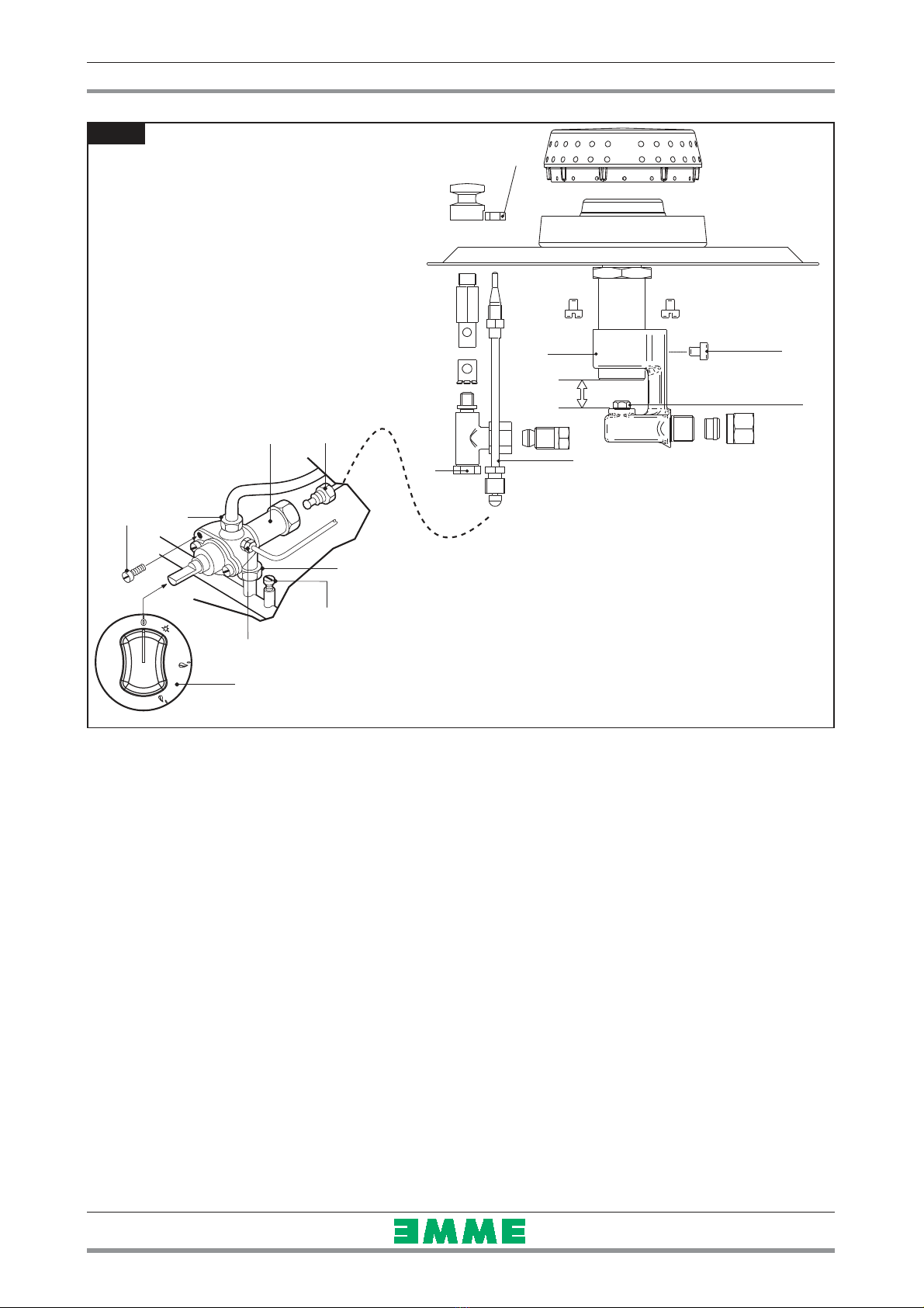
4.2.1 Cooking zone
• Burner with stabilized flame.
• Pilot flame.
• as cocks with safety and adjustable from maximum to minimum.
• Thermoelectric ignition safety.
• The bodies of the burners are made of nickelled cast-iron, the
flame spreaders are made of brass.
• 18/10 chrome-nickel steel cooking top.
• Knobs in thermosetting material.
4.2.2 Oven
The cooking chamber is made of stainless steel.
The runners for the pans are made of chromium-plated steel.
Extractable chromium-plated steel grill.
The door, with double wall and thermal insulation, is equipped with
an insulated handle and a hinge with balanced spring.
The insulation of the cooking chamber is rockwool.
Gas version GN 2/1
The tubular burners are in stainless steel and are resistant to thermal
and mechanical stress.
as is supplied through a safety valve with a thermostat.
Temperature adjustment between 150°C and 300°C, is made with the
thermostat.
The main burner is switched on from a pilot burner with safety ther-
mocouple.
The pilot burner has a piezo ignition.
The bottom of the oven, in cast iron with reinforced ribs is in two
piece for easy extraction.
The smoke collector is in aluminised sheet metal and the protection
grill is in enamelled cast iron.
Electric version GN 2/1
The heating elements are in the top (upper heat) and under the
bottom (lower heat).
Temperature adjustment between 50°C and 300°C is made by a
thermostat connected to a tri-polar switch.
It is possible to turn on the upper and lower heating elements sepa-
rately or at the same time.
The lighting of the heating element is indicated by 2 indicator
lights.
The upper heating elements are visible (grill), while the lower ones
are covered by a sheet of stainless steel.
Electric version GN 1/1 ventilated
The heating element is place in the rear around the fan and is pro-
tected by a bulkhead. Temperature adjustment between 50°C and
300°C is made by a thermostat connected to a switch.
The lighting of the heating element is indicated by 2 indicator
lights.
4.3 Assembly
4.3.1 Installation premises
This is a type A1 appliance. It must be installed in an adequately
ventilated room in order to avoid potentially unacceptable concen-
trations of harmful substances in the space in which the appliance is
installed. This room must meet all applicable local and national reg-
ulations.
The appliance must be installed in an adequately ventilated room in
order to ensure the air flow necessary for combustion, in accor-
dance with all applicable local and national regulations.
The appliance can be installed on its own or with other similar
equipment.
If the appliance is to be installed near inflammable walls, a minimum
distance of 150 mm around the sides and back should be allowed.
If this distance cannot be obtained, take proper heat-protection
action such as fitting tiles or thermal radiation protection material
to the walls.
Before connecting the appliance to the gas supply, check on the
data plate that the appliance is suitable and type-tested for the
type of gas available.
If the type of gas indicated on the data plate of the appliance does
not correspond to the gas which is present, refer to the paragraph
5.1.10 “Conversion and adaptation”.
4.3.2 Statutory regulations and technical requirements
During installation of the appliance, the following regulations must
be adhered to:
• Relevant legal directives;
• Local building and combustion regulations;
• "Technical rules for gas systems" worksheet;
• "Technical rules for liquid gas" worksheet;
• “ as installations in industrial kitchens” worksheet;
• Relative accident prevention standards;
• Local gas utility regulations;
• Local building and fire codes.
8· 20
0837_GB_99 - AS KITCHENS WITH PILOT

5.1 Preparation and tart-up
Before starting up the appliance, remove the protective wrapping.
Then carefully clean the working surface and the external parts with
lukewarm water and detergent, using a damp rag to remove all traces
of anti-rust material applied in the factory, then dry with a clean cloth.
5.1.1 Start-up
Before starting up the appliance, check that its specifications (cate-
gory and type of gas used) match those of the family and group of
the gas available locally.
If not, it is necessary to adapt the appliance to the gas family or
group required (see paragraph 5.1.10 “Conversion and adaptation”).
To start up the appliance, see the instructions for regular use.
5.1.2 Check of power
The appliances must be used with the specific injectors for the nomi-
nal power.
The power may be:
• the nominal power indicated on the data plate of the appliance;
• the reduced capacity power.
These injectors are shown in table 1.
Nominal power is also obtained in respect of the supply pressure:
• from 15 to 22.5 mbar for gases of the second family ( 20/methane)
• from 25 to 45 mbar for gases of the 3rd family
( 30/butane, 31/propane)
The appliance shall not be operated outside the above-mentioned
pressure ranges.
To adjust power with reduced capacity, use the data in table 1.
If you wish to further check the nominal power, you may do so by
using a gas meter according to the so-called "volumetric method".
A simple inspection is usually enough to check if injectors are func-
tioning correctly.
5.1.3 Checking the input pressure
Input pressure should be measured using a fluid measuring gauge
(e.g. a gooseneck pipe, min. resolution 0.1 mbar).
Remove lock screw (pos. 22 fig. 1) from the pressure intake tube and
connect the gauge hose: once measurement is complete, replace the
screw and do a seal check using a leak detector spray.
5.1.4 ower check with volumetric method
Using a gas meter and a stopwatch, you can read the volume of gas
output per time unit. The correct volume corresponds to the value
"E" expressed in litres/hour (l/h) or litre/minute (l/min).
The following formula is used to calculate the value of “E”:
It is important measure the power when the appliance is in standby
status.
The calorific power value can be requested from the local gas company.
The nominal power and the minimum power with respect to the
nominal pressure are obtained by consulting the table for the
adjustment of the gas passage (table 1).
WARNING
There is no pre-adjustment device for the nominal
power.
E =Power
Operating calorific value
4 - IN TALLATION IN TRUCTION
5 - ET-UP FOR OPERATION
9· 20
4.3.3 Installation
Before installation, gas connection, power check, conversion or adju-
stment and start up ask for gas supply company advice.
4.3.4 Gas connection
The gas connection may be made with a continuous wall, stainless
steel flexible hose with a maximum extension of 1.5 metres, in accor-
dance with all applicable local and national regulations. Hoses must
not pass through spaces which might become crammed with items
and they must not come into contact with any moving parts such as
drawers.
After completing gas connection, check for leaks using a special
leak-detector spray.
4.3.5 Electrical connection
Before connecting the unit to the mains, check that:
• The mains voltage corresponds to the values shown on the data
plate;
• The earth is in working order;
• The power cord is suitable to the electrical input of the appli-
ance (see table 1 pag. 7) and approved. The cord must be at least
type H07 RN-F.
The ground wire must be long enough to prevent tug after the
cable lead wires in case of raceway breakage.
Also, up the line from the unit, there must be a device with contact
opening of at least 3 mm which makes it possible to disconnect the
appliance in omnipolar mode.
To this end, for example, safety contactors may be used.
The omnipolar switch must be located near the appliance and be
readily accessible.
4.3.6 Equipotential
The appliance must be hooked up to a unipotential system.The
required terminal is located near the power cable and it is marked
by a tag with a symbol .
The manufacturers cannot be held responsible for any dam-
age due to inadequate or incorrect installation. Under such
circumstances the guarantee will be considered null and void.
0837_GB_99 - AS KITCHENS WITH PILOT

5 - ET-UP FOR OPERATION
10 · 20
0837_GB_99 - AS KITCHENS WITH PILOT
6
8
7
9
22
5
4
21
A1
2
3
11
17
14
Fig. 1

5 - ET-UP FOR OPERATION
5.1.5 ower check for operation with liquid gas
Check if the type of injectors used meet the data of the table 1.
Check that the pressure reducer installed in the system has an outlet
pressure which is compliant with paragraph 5.1.2 "Check of power"
(can be checked on the data plate of the appliance or on the table
1).
5.1.6 Operation control
• Start the appliance in accordance with the instructions.
• Check that the appliance does not have any leaks by using a leak-
detecting spray.
• Check ignition and that flame on the main burner lights properly
and is correctly formed, even on low.
• A servicing and maintenance contract is recommended.
5.1.7 Check of pilot flame
For proper regulation, the pilot flame must surround the thermocou-
ple and it must have a perfect appearance; otherwise, check gas
pressure, make sure the injector is clean and has the right diameter
for the gas, see table 1.
5.1.8 Checking the primary air
Both the oven and the open flames are equipped with primary air
adjustment. Air volume flow is correct when there is sufficient pro-
tection against the flame rising when the burner is cold or in case of
flashback when the burner is hot. See table 1.
5.1.9 Operator training
• Explain and show the user how the machine works according to
the instructions, and hand him this manual.
• Remind the user that any structural alterations or any building
modification or renovation may affect the combustion air supply,
thus requiring a second operation check.
5.1.10 Conversion and adjustment
To change over form one kind of gas to another, for example from
methane to liquid gas, or to another type of gas, the use of suitable
injectors for the main burner is required, in accordance with the
table 1.
The injectors of the main burners and pilot for different types of
gas, marked with the relative diameter in hundredths of mm, are in
an envelope which is provided with the appliance. If injectors are
not available please contact the factory with model and serial num-
ber written on technical data sticker. After transformation or adap-
tation, carry out operating checks as described in paragraph 5.1.6
“Operation control”.
5.1.11 Replacing of open burners injectors
To replace the injector (pos. 1 fig. 1): remove the control panel.
Then unscrew the screw (pos. 2 fig. 1), which secures the injector-
holder (pos. 3 fig. 1), move the injector-holder to make the injector
accessible, replace the injector with one able for the type of gas, see
table 1, reinstall everything in reverse order.
After fitting the new injectors, reset primary air distance “A” (fig. 1)
see table 1, and fasten the bushing with the appropriate screw.
After the replacement check the seal using a leack detector spray.
5.1.12 Replacement of pilot injectors of open flames
To replace the injector (pos. 12 fig. 1): remove the control panel.
Then unscrew the nut (pos. 11 fig. 1), pull down the nut together
the spring, unfix the injector and replace the injector with one able
for the type of gas, see table 1, install in reverse order.
After the replacement check the seal using a leack detector spray.
5.1.13 Setting reduced capacity power
The minimum setting screw (pos. 5 fig. 1) should be adjusted as fol-
lows:
• for operation with LP it should be screwed all the way down;
• for operation with methane, use the gas flow table to check the
value in l/min with respect to the operating alorific value (mea-
surement in accordance with the volumetric method). Start the
appliance in accordance with the instructions. Turn the knob to
the minimum position and use screw (pos. 5 fig. 1) to adjust the
flow (clockwise = flow reduction; conter-clockwise = flow
increase).
5.1.14 Replacement of burner injector of gas oven GN 2/1
Remove the front/lower unscrew the fixing sight screws. Unscrew
the screw fixing the hanger (pos. 2 fig. 2) of the injector-holder
(pos. 3 fig. 2), unscrew the screw (pos. 5 fig. 2) and extract the injec-
tor-holder from its housing. Now the injector (pos. 4 fig. 2) is easily
accessible, replace the injector with one able for the type of gas, see
table 1, install in reverse order.
After fitting the new injectors, reset primary air distance “A” see
table 1.
After the replacement check the seal using a leack detector spray.
5.1.15 Replacement of pilot injector of gas oven GN 2/1
Remove the front/lower unscrew the fixing sight screws.
Remove the plug
(pos. 11 fig. 2) and
with the help of a screwdriver
unscrew the injector (pos. 12 fig. 2), replace the injector with one
able for the type of gas, see table 1, install in reverse order.
At last replace the plug (pos. 11 fig. 2) and gasket (pos. 13 fig. 2).
After the replacement check the seal using a leack detector spray.
5.2 Maintenance
Attention! Before doing any repair or maintenance
work, unplug the appliance.
The following maintenance program should be carried out at least
once a year by qualified personnel with license:
• Check that all the safety and adjustment devices are working
properly;
• Check that the burners are working properly with regard to:
- ignition
- combustion safety;
Check functioning of the appliance as described in paragraph 5.1.6
“Operation control”.
If it should be necessary to clean the open flame burners, proceed
as follows:
• Remove the grills, the flame spreaders and the bodies of the
burners;
• Clean the parts with water and detergent and an appropriate
tool. Rinse and dry.
When reassembling the parts, make sure you place them back in the
right position.
If it is necessary to clean the oven burner (pos. 18 fig. 2) proceed as
follows:
• Remove the lower panel as described previously. Unscrew the
screw fixing the hanger (pos. 2 fig. 2) of the injector-holder
(pos. 3 fig. 2), unscrew the screw (pos.5 fig. 2) fixing the burner
to the injector-holder and xtract the injector-holder from its
housing;
• Unscrew the fastening screw (pos. 19 fig. 2) of the burner and
remove it;
• Carefully clean all the holes of the burner with the aid of a tip
of a suitable size;
• Check that the smoke discharge is clear;
• Reinstall everything in reverse order.
11 · 20
0837_GB_99 - AS KITCHENS WITH PILOT

5 - ET-UP FOR OPERATION
After the replacement check the seal using a leack detector spray.
5.3 Replacing parts
All parts must be replaced by authorized technicians
only!
To replace the following parts first remove all the control knobs and
control panel (after loosening the fixing screws), then extract the
ignition wire.
5.3.1 Open flame gas cock
Loosen the fitting of the pipes (pos. 6 and 9 fig. 1) of the gas and of
thermocouple (pos. 8 fig. 1), loosen the fitting (pos. 7 fig. 1) fixing
the cock on the gas piping and replace the piece (pos. 4 fig. 1) install
in reverse order. After the replacement check the seal using a leack
detector spray.
5.3.2 Open flame thermocouple
Loosen the nut (pos. 8 fig. 1) for fastening the thermocouple on the
valve and on the burner (pos. 17 fig. 1) and replace the piece (pos.
14 fig. 1) install in reverse order.
5.3.3 Gas valve gas oven GN 2/1
Loosen the fittings (pos. 1,2,3 and 4 fig. 3) which are for the connec-
tion for the gas pipe and the thermocouple, remove the coil of the
thermostat from its place in the cooking chamber and put in a new
piece in the reverse order. After the replacement check the seal
using a leack detector spray.
5.3.4 lug gas oven GN 2/1
Unscrew the fastening screws and remove the lower panel, extract
the ignition wire and unscrew the screws (pos. 15 fig. 2), unscrew
the screw (pos. 20 fig. 2) fixing the pilot on the support, pull down
the pilot to a more convenient position and put in a new piece (pos.
16 fig. 2) install in reverse order.
5.3.5 Thermocouple gas oven GN 2/1
Unscrew the screws (pos. 15 fig. 2), the nut (pos. 4 fig. 3) fixing the
thermocouple on the valve and put in a new piece (pos. 14 fig. 2)
install in reverse order.
5.3.6 Main burner gas oven GN 2/1
Remove the front/lower panel by removing the fastening screws.
Unscrew the screws fixing the hanger (pos. 2 fig. 2) of the injector-
holder (pos. 3 fig. 2), unscrew the screw (pos.5 fig. 2) and extract
the injector-holder from its housing, unscrew the screws rear fixing
(pos. 19 fig. 2) of the burner and put in a new piece in the reverse
order. After the replacement check the seal using a leack detector
spray.
After any maintenance or repair work, replace the con-
trol panel and the lower panel.
After replacing gas input components, check operation
again and test for leakage.
5.3.7 Heating elements of electric oven GN 2/1
Unplug the appliance from the electrical mains!
The lower heating elment (pos. 1 fig. 4) is placed under the bottom.
The upper heating elment (pos. 2 fig. 4) element is attached to the
top of the cooking chamber.
To remove the heating elements, unscrew the screw that attach
themto the corresponding flange, pull the heating elements and
relative wires forward.
Use a screwdriver to disconnect the wires and install a new heating
element in reverse order.
5.3.8 Heating element of electric oven GN 1/1
Unplug the appliance from the electrical mains!
To remove the heating element (pos. 6 fig. 5), remove the rear bulk-
head, unscrew the screws fixing the the heating element to the
oven, pull the heating element forward with relative wires.
Disconnect the wires, and install a new heating element in reverse
order.
5.3.9 Fan of of electric oven GN 1/1
Unplug the appliance from the electrical mains!
To replace the fan remove the back unscrew the sight screws, discon-
nect the wires from the motor, from the inside of the chamber
12 · 20
15
14
11 12
13 16
18
19
3 4
2
5
20
Fig. 2
0837_GB_99 - AS KITCHENS WITH PILOT

13 · 20
5 - ET-UP FOR OPERATION
remove the rear bulkhead fan cover and the fan (pos. 1 fig. 5) by
loosening the locking nut (pos. 2 fig. 5 “NB. the nut is with left
thread”).
Loosen the bolts (pos. 3 fig. 5) hat hold the motor (pos. 4 fig. 5) on
the oven and pull off from rear. Re-install in reverse order position-
ing in the correct way the seal protection (pos. 5 fig. 5) and power
mains.
5
1
2
3
7
6
4
7
6
5
4
3
2
1
Fig. 3
0837_GB_99 - AS KITCHENS WITH PILOT

6 - IN TRUCTION FOR U E
6.1 afety, cleaning and repair rules
• This appliance is used for the preparation of meals at industri-
al level. Usage and cleaning can be carried only by expert per-
sonnel. Maintenance and repair can be carried out only by
skilled technical personnel.
• These indications must be communicated to all those con-
cerned during internal training.
• Attention! This appliance must be constantly watched over
when being used!
• rease and overheated oil can catch fire. Use this appliance
only under constant control. Never use water to put out
grease or oil! Cover with a lid, turn off the hot plate and
remove pot from the burner.
• Do not leave the burners running.
• Do not overload the kitchen. For proper use, pots should
not be bigger than the flames.
• Parts of the appliance and attachments exposed to food
must be cleaned with detergents and rinsed thoroughly with
potable water.
• Do not clean the appliance using water jets or steam,
whether direct or pressurized!
• If the room is being cleaned with water/steam jets or high-pres-
sure equipment, it is necessary to switch off the appliance first!
• Before starting to clean the appliance, disconnect from the
mains.
• Do not use inflammable liquid to clean the appliance.
• Repairs may be carried out only by skilled personnel.
• During repairs, the appliance must undergo voltage
omnipolar insulation (local switch, i.e. safety load cut-off
switch).
• Noise emission values of the appliance in operation are below
70dB (A). This value is compulsory according to certain national
safety standards.
WARNING
Attention! The manufacturer declines all responsibility concern-
ing mistakes included in these instructions due to translating or
printing errors: the manufacturer also reserves the right to
change the product as he see fits, though without changing its
essential features. The manufacturer declines all responsibility for
any non-compliance with the provisions contained in this manu-
al.
6.2 tart-up
6.2.1 Lighting and disconnecting flame burner with pilot
Turn the knob of the desired burner to the left (pos. 21 fig. 1)
to position. Press all the way down and use a match or other
suitable instrument to light the pilot burner.
Keep the knob pressed down for another 15-20 seconds: if the pilot
flame goes out after the knob is released, start again.
Then place the knob in the maximum or minimum position so that
the main burner ignites. Burner power regulation must be done
between the max ( ) and min. ( ) supply position of easily
selectable intermediate levels.
To shut off the burner, turn the knob to the right to position,
the main burner will go out.
To shut off the pilot light, place the knob in position “0”.
6.3 Lighting and shutdown of electric oven
GN 2/1
Turn selector (pos. 1 fig. 4A), right or left to choose the type of
cooking, heat from above and/or below.
With knob (pos. 4 fig. 4A) turn the thermostat from the “0” posi-
tion to a desired temperature between 50°C and 300°C; the indica-
tor light will come on; the green one (pos. 2 fig. 4A) shows that the
appliance is on, the yellow one (pos. 3 fig. 4A) indicates that the
heating elements are operational, as soon as the set-up temperatu-
re is reached, the indicator light goes off.
To turn the appliance off, turn the knobs to position “0”.
14 · 20
1
2
2
3
1
4
Fig. 4 Fig. 4A
0837_GB_99 - AS KITCHENS WITH PILOT

6 - IN TRUCTION FOR U E
6.4 Lighting and shutdown of electric oven GN 1/1
With knob (pos. 1 fig. 5A) turn the thermostat from the “0” position
to a desired temperature between 50°C and 300°C; the indicator
light will come on; the green one (pos. 2 fig. 5A) shows that the
appliance is on, the yellow one (pos. 3 fig. 5A) indicates that the
heating elements are operational, as soon as the set-up temperature
is reached, the indicator light goes off.
To turn the appliance off, turn the knob to position “0”.
6.5 Lighting and shutdown of gas oven GN 2/1
6.5.1 Lighting the pilot gas oven GN 2/1
Press the knob (pos. 5 fig. 3) and turn it to the left until posi-
tion. Hold the knob down and at the same time press the piezo igni-
tion button (pos. 6 fig. 3) repeatedly until the pilot comes on.
Ignition of the pilot can be seen through the hole in the cooking
chamber (with the door open). Hold the knob down for about 15-20
seconds. If, when the knob is released, the pilot light goes out,
repeat the operation.
6.5.2 Lighting the main burner and temperature adju-
stment gas oven GN 2/1
To light the main burner, turn the knob further to the left until the
desired temperature. The thermostat is marked in positions from 1
to 7. The approximate values for each position are the following:
Pos t on 1 2 3 4 5 6 7
Degrees °C 160 175 195 220 240 265 290
To shut off the main burner, turn the knob to the right until
position, the main burner will go out.
To shut off the pilot light, place the knob in position “0”.
6.6 Turning the appliance off in case of
breakdown
6.6.1 What to do in case of failure
In case of breakdown or malfunctioning or failure close the gas cock
and the oven. Close the connecting cock of the unit and switch off
any electric power. Call the service centre.
6.6.2 What to do in case of prolonged period of disuse
When the appliance is not to be used for a long time, clean thor-
oughly, cas instructed in the chapter 6.7 “Appliance care and fre-
quency of maintenance”, close the connecting cock of the unit and
switch off any electric power.
6.7 Appliance care and frequency of maintenance
Attention! When cleaning, carefully avoid washing the
appliance with direct water jets or high-pressure
water!
Cleaning must be performed when the appliance is cold.
Thorough daily cleaning of the appliance, after disconnecting it, will
keep it in perfect working order and make it last longer. All steel
parts should be cleaned with water and a detergent, using a damp
cloth; do not use abrasive substances or corroding detergents.
Do not use steel wool, which could cause rust to form.
For the same reason, avoid touching the appliance with anything
made of iron. Do not clean with sandpaper and lubricating gel paper.
If absolutely necessary, you may use pumice powder.
If the appliance is extremely dirty, use a synthetic sponge (i.e.
Scotchbrite sponge).
After cleaning the appliance, rinse with clean water and wipe with
a clean cloth.
If the main burner needs cleaning, proceed as follows:
• Remove the pan support, cover, rings and burner crown;
• Clean burner parts with water, soap and a suitable tool, then
rinse and wipe;
• When reassembling the parts, make sure you place them back in
the right position.
All maintenance and repair work must be carried out by authorized
technicians only.
The appliance must be checked at least once a year. For this reason,
a service agreement contract is recommended.
6.8 Recommendations for the treatment of
stainless “steel industrial” kitchens
6.8.1 Useful information on “stainless steel”
Industrial kitchens are generally made of “stainless steel” having
the following material codes:
• 1.4016 or 1.4511 = magnetizable chromed steels
• 1.4301, 1.4401 and 1.4571 = non-magnetizable chromed steels
Chromed steels have favourable thermo-technical characteristics. In
15 · 20
1
4
5
6
2 3
32 1
Fig. 5 Fig. 5A
0837_GB_99 - AS KITCHENS WITH PILOT

6 - IN TRUCTION FOR U E
fact, they have less of a tendency to warp due to the effect of heat.
Chrome-nickel steels, instead, have good corrosion resistance features.
“Stainless steel” corrosion resistance is given by an inactive coat that
builds up on the surface by coming into contact with oxygen.
The oxygen in the air is already enough to build up the inactive coat
that allows automatic removal of anomalies and damage due to
mechanical actions. The inactive coat builds up or re-builds up faster
if the steel comes in contact with running water containing oxygen.
A more powerful effect is given by oxidative acids (nitric acid, oxalic
acid). These acids are used if the steel has undergone strong chemi-
cal stresses, hence generally losing its inactive coat.
The inactive layer can be chemically damaged or jeopardized by
reducing agents (oxygen consumption) if they come in contact with
the steel, concentrated or at high temperatures. These active sub-
stances include for instance:
• saline and sulphurous substances
• chlorides (salts)
• concentrated spices such as mustard, vinegar essences, soup
cubes, kitchen salt solutions, etc.
More damage can be caused by:
• outside rust (i.e. from other components, tools or incipient rust)
• iron particles (i.e. file dust)
• contact with non-ferrous metals (element build up)
• lack of oxygen (i.e. no air inlet, water lacking oxygen).
6.8.2 Warnings and advice for maintenance of “stain-
less steel” appliances
• “Stainless” steel equipment surfaces must be kept clean and in
contact with air at all times. When not running, keep appliance
doors open so as to allow air to run through it.
• Regularly remove calcium , grease, starch, and egg white deposits
where rust may build up if there is lack of air. Do not use bleach-
ing products or products containing chloride. Follow all indica-
tions given by the company concerning special soaps and clean-
ing methods to be used for the appliance. If no specific cleaning
recommendations are available, it is necessary, however, to use
detergents having a low chloride content. After cleaning, remove
all soap residues with plenty of clean water and thoroughly dry
the surfaces.
• Minimize contact of “stainless steel” with concentrated acids,
spices, salts, etc. Even acid vapours coming from cleaning the tiles
favour “stainless steel” corrosion.
• Particularly for pots and multiple appliances, it is not recom-
mended to load the cooking chamber only with food having a
high salt content.
It is preferable to cook different food together, i.e. fatty dishes
or vegetables containing acids.
• Avoid damaging the “stainless steel” surface, in particular with
different metals. Residues from other metals help build up the
formation of chemical microelements that may cause rust. At any
rate, it is appropriate to avoid contact between iron and steel
since it produces rust. Any contact between “stainless steel” and
iron (steel wool, pipeline chips, chalybeate waters) can start cor-
rosion phenomena.
• As for mechanical cleaning, it is recommended to use only steel
wool or natural, plastic or steel bristle brushes. Steel wool or
brushes with “stainless steel” can cause rust due to rubbing. Newly
formed rust spots can be removed with slightly abrasive liquid
soaps or fine-grained sand paper. Larger rust spots can be removed
with 2-3% of hot oxalic acid solution. If these cleaning products do
not do the job, a nitric acid (10%) treatment is required.
Attention! These treatments can be carried out only by
expert personnel according to current regulations!
6.8.3 The 2002/96/EC (WEEE) Directive:
information to users
This informational note is meant only
for owners of equipment marked with
the symbol shown in fig. A on the adhe-
sive label featuring the technical specifi-
cations applied on the actual product
(the label also giving the serial number).
This symbol indicates that the product is classified, according to the
regulations in force, as an item of electrical and electronic equip-
ment and conforms to EU Directive 2002/96/EC (WEEE) meaning
that, at the end of its service life, it must be treated separately from
domestic waste, i.e. it must be handed in free of charge to a separa-
te waste electrical and electronic equipment collection centre or
returned to the reseller when buying a new equivalent item of
equipment.
The user is responsible for delivering the unit at the end of its life
to the appropriate collection facilities. Failure to do so shall result in
the user being subject to the penalties prescribed by the legislation
in force on waste.
Suitable separated collection so that the unit no longer used can be
sent off for environmentally compatible recycling, treatment and
disposal helps avoid possible negative effects on the environment
and on health and facilitates the recycling of the product's compo-
nent materials.
For more detailed information on available collection systems, con-
tact the local waste disposal service or the shop you purchased the
unit from.
Producers and importers fulfil their responsibility for environmental-
ly compatible recycling, treatment and disposal both directly and by
joining a collective scheme.
16 · 20
0837_GB_99 - AS KITCHENS WITH PILOT
Fig. A

7 - APPENDIX: ELECTRICAL DIAGRAM
17 · 20
400V 3N ~ 8.48 A
L1mA L 2 L 3 N PE
3
2
1
0
B2 5
P3 P5P4 P2P6
672134
B1
P1
1
P2
2
P3
3
P4
4
F1
B2
P3
5
P4
6
P6
P5
P2
72 1 3 4
1 3 52 4 6
1 3 52 4 6
R2
R1
H1 H2
F2
230V 3 ~ 14.75 A
1 3 52 4 6
R1/R2
230V ~ 25.7 A
1 3 52 4 6
R1/R2
L1 N
1mA2 3 4
1mA2 3 4
L1 L 2 L 3
M74NBFE
M76NBFE
0837_GB_99 - AS KITCHENS WITH PILOT
mA
B1
B2
F1
F2
R1-2
H1
H2
Terminal board
Switch
Commutator
Thermostat
Security thermostat
Heating element 980 W
reen indicator light
Yellow indicator light
Total power: 5.9 kW

7 - APPENDIX: ELECTRICAL DIAGRAM
18 · 20
mA
N L1 PE
B1
123
H1
H2
R1
F1
MV
F2
M74NBFXE
M76NBFXE
0837_GB_99 - AS KITCHENS WITH PILOT
mA
B1
R1
F1
F2
H1
H2
MV
Terminal board
Commutator
Heating element 2500 W
Thermostat
Security thermostat
reen indicator light
Yellow indicator light
Motorized fan
Total power: 2.5 kW

19 · 20
NOTES
0837_GB_99 - AS KITCHENS WITH PILOT

GIGA Grandi Cucine S.r.l. - Via Pisana, 336 - 50018 Loc. Olmo di Scandicci (FI) - Italy
Tel. +39 055 722 33 (11 linee r.a.) - Fax +39 055 7310056
www.gigagrandicucine.it - info@gigagrandidicucine.it
WARNING
THE MANUFACTURER CANNOT BE HELD RESPONSIBLE
FOR ANY INACCURACIES IN THIS BOOKLET DUE
TO COPYIN OR PRINTIN ERRORS.
DUE TO ITS POLICY OF CONTINUAL PRODUCT IMPROVEMENT,
THE MANUFACTURER RESERVES THE RI HT
TO MAKE ANY CHAN ES DEEMED NECESSARY.
THE MANUFACTURER CANNOT BE HELD RES ONSIBLE
IF THE INSTRUCTIONS CONTAINED IN THIS MANUAL
ARE NOT OBSERVED.
This manual suits for next models
7
Table of contents
Popular Cooker manuals by other brands

Moffat
Moffat GSC 5061 Operating and installation instructions

M-system
M-system MAXI OVEN PRF 950 IX Instruction for the use - installation advice

Creda
Creda J052E Instructions for installation and use

CONTINENTAL EDISON
CONTINENTAL EDISON CECDF5060IX2 user manual

Gastrorag
Gastrorag BT-350B-A manual

Ariston
Ariston CP 059 MD X AUS S Instructions for use and installation