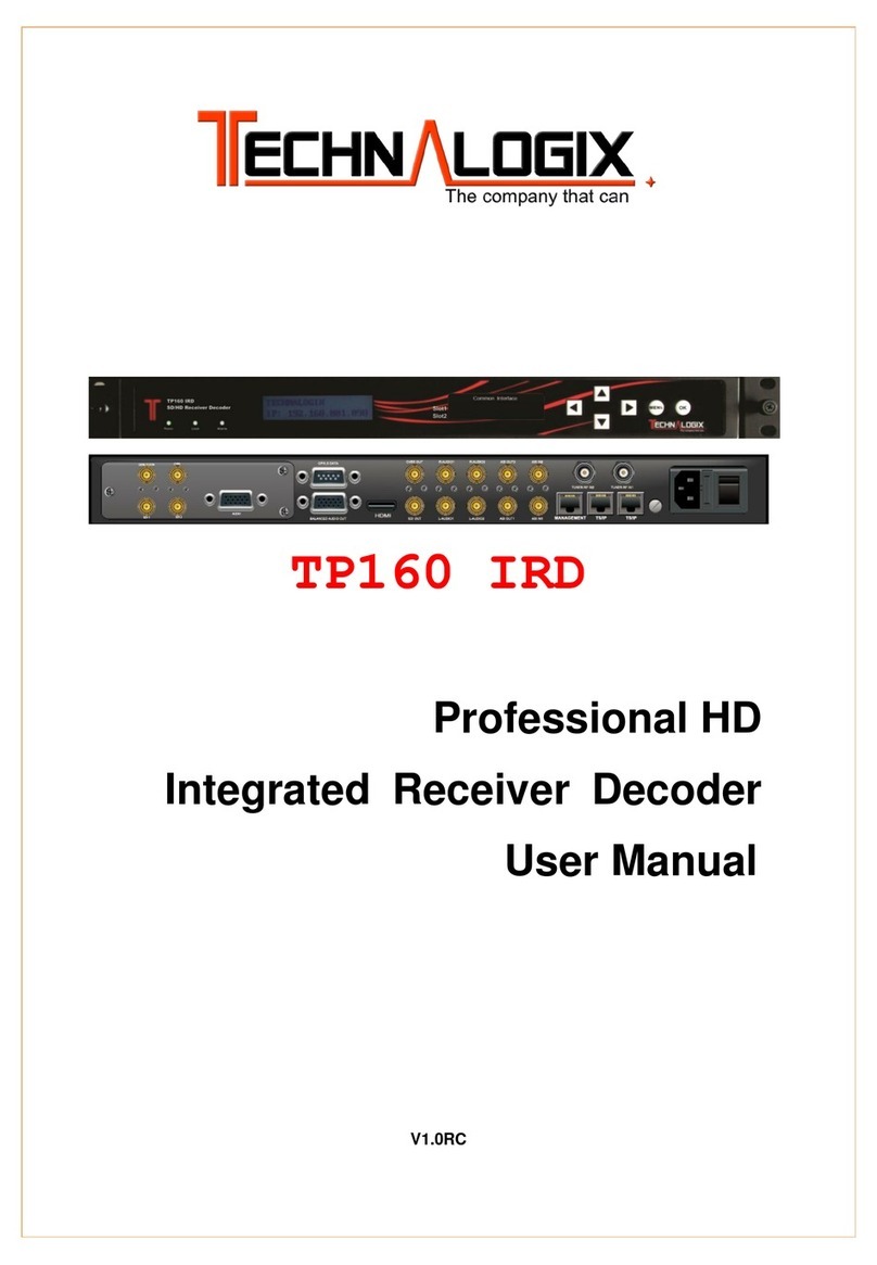
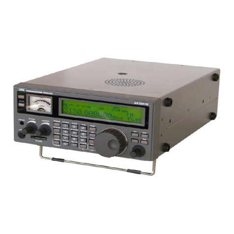
Emperor VST-2500 User manual

MODEL:VST-2500/VSR-2500AM
TINSE061C--001 PRINTED IN CHINA
2.4GHz
Wireless Video Sender Receiver
1
23
4
2
.
4
G
H
z
W
I
R
EL
E
S
S
R
E
C
EI
V
E
R
1
23
4
2
.
4
G
H
z
W
I
R
E
L
E
S
S
T
R
A
N
S
M
I
T
T
E
R

Table of Contents
1. Location of Controls On Sender
2. Location of Controls On Receiver
3. Channel & Timer Setting
4.
1
2
3
4
7. Specifications 8
AC/DC Adaptor Operation
4.
Connections/Setting up
Antenna Operation
6~7
6.
5. 5

1
23
4
2
.
4
G
H
z
W
I
R
E
L
E
S
S
T
R
A
N
S
M
I
T
T
E
R
Location of controls on Sender
81
1. Patch Antenna
2. Channel Indicator
3. Power ON/OFF Switch
4. DC Input Jack
5. Audio Jack
6. Video In
7. Channel Selector
Input
put Jack
Sender unit
1. Transmit Frequency: 2400~2483.5MHz
2. Microwave Output Power:94dbu(3m)
3. Modulation: FM
4. Maximum Frequency Deviation: 20 MHz
d). Audio Sub, Carrier Frequency: 6.0 MHz,
6.5MHz
7. Operation Current:200 MA Max.
8. Power Supply
Adaptor :DC 12V 0.2/0.3A
9. Dimension:
107W x43Hx123Dm/m
Receiver unit
1. Receiver Frequency:2400~2483.5MHz
2. Receiver Sensitivity:-80 ~ -85 dBm
3. Video Output: 1 Vpp 75 ohm
4. Audio Output: -8dBs 47K ohm
5. Monitor Center horizontal Resolution:
330 lines
6. Operation Current:
. Power Supply:
Adaptor: DC 12V 0.2/0.3A
8. Dimension:
200mA Max.
7
107W x43Hx123Dm/m
Specifications
General:
1.Operation Frequency: 2400MHz-2483.5MHz
2.Usable range: 50~100 Meter (open side)
5. Video: a) Input Impedance: 1Vpp 75 ohm
b) Frequency Response:0~5Mhz
6. Audio:
a) Input Impedance: 10K ohm
b) Interface Level:1 Vpp
c) Frequency Response:300-3400Hz
3. Operation Temperature:-10~50 C 1
2
FRONT
REAR
34567
CH VIDEO DC 12V IN
AUDIO
L
INPUT
R
AUDIO
ON OFF

1
23
4
2
.
4
G
H
z
W
I
R
EL
E
S
S
R
E
C
EI
V
E
R
Location of controls on Receiver
27
1. Patch Antenna
2. Channel Indicator
3. Power ON/OFF Switch
4. DC Input Jack
5. Audio Output Jack
6. Video
7. Channel Timer Selector
Output Jack TIMER
CH VIDEO DC 12V IN
AUDIO
L
OUTPUT
R
AUDIO
ON OFF
ON
123456
1
2
FRONT
REAR
34567
One Receiver can Receive 4 Channels sig al from 4 senders
with different direction or You can select any one even other
Combination which depends on channel setting.
The timer switch can select switcher time from 3 sec to 10 sec. Refer
to channel & timer setting.
1.Connet the Video and Audio output signal of receiver with AV wire
to your TV or Monitor . If connect to TV, You have to switch your TV
to V INPUT"function .
2. If your TV SET with AV output Jack .You can connect to a VCR for
recording.
"A
n
Receiver unit
TIMER
CH VIDEO DC 12V IN
AUDIO
L
OUTPUT
R
AUDIO
ON OFF
ON
123456
RED
WHITE
YELLOW
RED
WHITE
YELLOW
VIDEO
AUDIO
L
INPUT
R
AUDIO
REAR

VIDEO AUDIO
L
OUTPUT
R
AUDIO
3
Channel & Timer Setting
Sw5
Sw6
ON
ON OFF
ON OFF
ON OFF
Switcher
time
3sec 5sec 7sec 10sec
1.The channel & Timer selector on the
rear cabinet are used to set channel
&timer. Put Theswitch to ON position
and then you can select single channel
1~4 or any other channel combination.
2.Timer setting function as below.
123456
DIP ON
CH
TIMER
6
RECEIVER UNIT
Channel Setting
SENDER UNIT
The channel selector on the rear cabinet
are used to set channel No which you
want to transmit.
Put one of four switch to ON position
as you prefer.
Don t SET more than one channel to
on position.
OFF
123 4
ON
CH
Connections/setting up
REAR
CH VIDEO DC12V IN
AUDIO
L
INPUT
R
AUDIO
ONOFF
RED
WHITE
YELLOW
The sender can input video and stereo or mono audio signal from
camera, DVD, VCR, satellite receiver, TV--ect.and then transmit to
the Receiver without wire around 100 meters at the open side.
If indoor use ,the distance will Base on the building construction.
1.Conect the yellow plug into the video input Jack of sender
2.Conect the red plug into the audio R input Jack of sender
3.Conect the white plug into the audio L input Jack of sender
4.Plug the other end to the signal source, be sure that yellow plug
into video output ,red plug to the R channel of Audio output ,white
plug into the L channel of Audio output.
RED
WHITE
YELLOW
Sender unit

5
4
Make sure that proper AC/DC adaptor
have been installed correctly, use only
the AC/DC adaptor supplied with the
sender and receiver
TIMER
CH VIDEO DC 12V IN
AUDIO
L
OUTPUT
R
AUDIO
ON OFF
ON
123456
1. Plug of the AC/DC Adaptor to the
DC input jack of the unit. Plug the adaptor
into a standard wall outlet.
2. Switch on the power switch of the unit.
3. The channel indicator LED will be illuminated.
AC/DC Adaptor Operation
AC/DC Adaptor
Make sure that both units are on the
same channel.
Antenna Operation
1. If the sender unit is far away from the
Receiver unit , pls turn TX side of antenna on
unit to directly face antenna on Receiver unit
to get best reception.
2. If the is close to the
, due to multi path reason,
sometimes you have to put both antennas
of & to face
upward to void something moving between
TX and RX which may affect the picture
stability.
sender unit
Receiver unit
sender unit Receiver unit
RF
3. Place the sender unit in the most
appropriate location for monitoring
(tabletop, dresser or wall mount) as
higher as possible.
TX SIDE OF ANTENNA
RF SIGNAL UPWARD
4. In case of poor display quality, rotate
the antennas or reposition both units
to obtain optimum picture transmission.
1
23
4
2
.
4
G
H
z
W
I
R
E
L
E
S
S
T
R
A
N
S
M
I
T
T
E
R

This manual suits for next models
1
Table of contents
