EMS Wireless EkoMini M1.9 User manual

5015 B.U. Bowman Drive Buford, GA 30518 USA Voice: 770-831-8048 Fax: 770-831-8598
FCC Part 24
Transmitter Certification
Test Report
FCC ID: DNY0A1MINIM1900
FCC Rule Part: CFR 47 Part 24E
ACS Report Number: 06-0115-24E
Manufacturer: EMS Technologies, Inc.
Model: EkoMini M1.9
Operator’s Manual

IM 610179-1, Rev 02
08/25/06 Page 1
EkoMini M1.9
IN-DOOR REPEATER MANUAL
2850 Colonnades Court
Norcross, Georgia 30071
Tel: 770.582.0555
Fax: 770.729.0075

IM 610179-1, Rev 02
08/25/06 Page 2
Disclaimer
Every attempt has been made to make this material complete, accurate, and up-to-date. Users
are cautioned, however, that EMS Wireless reserves the right to make changes without notice
and shall not be responsible for any damages, including consequential, caused by reliance on
the material presented, including, but not limited to, typographical, arithmetical, or listing errors.
Copyright Information
© EMS Wireless, Norcross, Georgia
WARNINGS, CAUTIONS, AND GENERAL NOTES
This product conforms to FCC Part 15, Section 21. Changes or modifications not expressly
approved by the party responsible for compliance could void the user's authority to operate the
equipment.
In accordance with FCC regulations regarding human exposure to radio frequency energy, this
device shall be installed such that a minimum separation distance of 20cm is maintained between it
and general population.
This Class B digital apparatus meets all requirements of the Canadian Interference Causing
Equipment Regulations. Operation is subject to the following two conditions: (1) this device may not
cause harmful
interference, and (2) this device must accept any interference received, including interference that
may cause undesired operation.
Cet appareillage numérique de la classe B répond à toutes les exigences de l'interférence
canadienne causant des règlements d'équipement.L'opération est sujette aux deux conditions
suivantes: (1) ce dispositif peut ne pas causer l'interférence nocive, et (2) ce dispositif doit accepter
n'importe quelle interférence reçue, y compris l'interférence qui peut causer l'opération peu désirée.
RF Exposure
In accordance with FCC requirements of human exposure to radiofrequency fields, the server
and donor radiating elements shall be installed such that a minimum separation distance of 20
cm and 23 cm, respectively, is maintained between the radiating element and the general
population.
Safety Considerations
When installing or using this product, observe all safety precautions during handling and
operation. Failure to comply with the following general safety precautions and with specific
precautions described elsewhere in this manual violates the safety standards of the design,
manufacture, and intended use of this product. EMS Wireless assumes no liability for the
customer's failure to comply with these precautions.

IM 610179-1, Rev 02
08/25/06 Page 3
WARNING
WARNING calls attention to a procedure or practice, which if ignored, may result in damage to
the system or system component. Do not perform any procedure preceded by a WARNING
until described conditions are fully understood and met.
Warning -- For Your Safety
Disconnect all power before servicing the unit.
Install the product securely on a stable surface in a protected location where no one can step or
trip over the supply cord and where the supply cord will not be damaged.
Do not expose this device to rain or other moisture.
The input voltage range is 100 – 240 VAC, Single Phase, 50 – 60 Hz.
Use only a grounded electrical outlet when connecting the unit to a power source. If you do not
know whether the unit is grounded, consult a qualified electrician.
A readily accessible disconnect device that is suitably approved and rated shall be incorporated
into the field wiring.
If You Need Help
If you need additional copies of this manual, or have questions about system options, or need
help with installation and using of the system, please contact EMS Wireless' Customer Support
Department.
EMS Wireless
Customer Support Department
2850 Colonnades Court NW, Norcross, GA 30071
770.582.0555 x5310
Service
Only authorized service personnel will service any part of this product and only in accordance
with procedures outlined in this manual. If the product does not meet its warranted
specifications, or if a problem is encountered that requires service, notify EMS Wireless'
customer support department. Service will be rendered according to the EMS Wireless'
warranty and repair policy. The product shall not be returned without contacting EMS Wireless
and obtaining a return authorization number from the Customer Support department.
When returning a product for service, include the following information: Owner, Model Number,
Serial Number, Return Authorization Number (obtained in advance from EMS Wireless
Customer Support Department), service required and/ or a description of the problem
encountered.
Warranty and Repair Policy
The EMS Wireless Quality Plan includes product test and inspection operations to verify the
quality and reliability of our products.

IM 610179-1, Rev 02
08/25/06 Page 4
EMS Wireless uses every reasonable precaution to ensure that every device meets published
electrical, optical, and mechanical specifications prior to shipment. Customers are asked to
advise their incoming inspection, assembly, and test personnel as to the precautions required in
handling and testing ESD sensitive opto-electronic components. Physical damage to the
external surfaces voids warranty.
These products are covered by the following warranties:
1. General Warranty
EMS Wireless warrants to the original purchaser all standard products sold by EMS Wireless to
be free of defects in material and workmanship for the duration of the warranty period of one (1)
year from date of shipment from EMS Wireless. During the warranty period, EMS Wireless'
obligation, at our option, is limited to repair or replacement of any product that EMS Wireless
proves to be defective. This warranty does not apply to any product, which has been subject to
alteration, abuse, improper installation or application, accident, electrical or environmental over-
tress, negligence in use, storage, transportation or handling.
2. Specific Product Warranty Instructions
All EMS Wireless products are manufactured to high quality standards and are warranted
against defects in workmanship, materials and construction, and to no further extent. Any claim
for repair or replacement of a device found to be defective on incoming inspection by a
customer must be made within 30 days of receipt of the shipment, or within 30 days of discovery
of a defect within the warranty period.
This warranty is the only warranty made by EMS Wireless and is in lieu of all other warranties,
expressed or implied, except as to title, and can be amended only by a written instrument
signed by an officer of EMS Wireless. EMS Wireless customer support representatives are not
authorized to make commitments on warranty returns.
In the event that it is necessary to return any product against the above warranty, the following
procedure shall be followed:
a. Return authorization shall be received from the EMS Wireless Customer Support prior to
returning any device. Advise EMS Wireless Customer Support of the model, serial number, and
the discrepancy. The device shall then be forwarded to EMS Wireless, transportation prepaid.
Devices returned freight collect or without authorization may not be accepted.
b. Prior to repair, EMS Wireless Customer Support will advise the customer of EMS
Wireless test results and will advise the customer of any charges for repair (usually for customer
caused problems or out-of-warranty conditions).
If returned devices meet full specifications and do not require repair, or if non-warranty repairs
are not authorized by the customer, the device may be subject to a standard evaluation charge.
Customer approval for the repair and any associated costs will be the authority to begin the
repair at EMS Wireless. Customer approval is also necessary for any removal of certain parts,
such as connectors, which may be necessary for EMS Wire- less testing or repair.

IM 610179-1, Rev 02
08/25/06 Page 5
c. Repaired products are warranted for the balance of the original warranty period, or at least 90
days from date of shipment.
3. Limitations of Liabilities
EMS Wireless' liability on any claim of any kind, including negligence, for any loss or damage
arising from, connected with, or resulting from the purchase order, contract, or quotation, or
from the performance or breach thereof, or from the design, manufacture, sale, delivery,
installation, inspection, operation or use of any equipment covered by or furnished under this
contract, shall in no case exceed the purchase price of the device which gives rise to the claim.
EXCEPT AS EXPRESSLY PROVIDED HEREIN, EMS WIRELESS MAKES NO WAR- RANTY
OF ANY KIND, EXPRESSED OR IMPLIED, WITH RESPECT TO ANY GOODS, PARTS AND
SERVICES PROVIDED IN CONNECTION WITH THIS AGREEMENT INCLUDING, BUT NOT
LIMITED TO, THE IMPLIED WARRANTIES OF MERCHANTABILITY AND FITNESS FOR A
PARTICULAR PURPOSE. EMS WIRE- LESS SHALL NOT BE LIABLE FOR ANY OTHER
DAMAGE INCLUDING, BUT NOT LIMITED TO, INDIRECT, SPECIAL OR CONSEQUENTIAL
DAMAGES ARISING OUT OF OR IN CONNECTION WITH FURNISHING OF GOODS, PARTS
AND SERVICE HEREUNDER, OR THE PERFORMANCE, USE OF, OR INABILITY TO USE
THE GOODS, PARTS AND SERVICE.
EMS Wireless test reports or data indicating mean-time-to-failure, mean-time-between-failure,
or other reliability data are design guides and are not intended to imply that individual products
or samples of products will achieve the same results. These numbers are to be used as
management and engineering tools, and are not necessarily indicative of expected filed
operations. These numbers assume a mature design, good parts and no degradation of
reliability due to manufacturing procedures and processes.
Introduction
EkoMini is quick and easy to install, using a minimum set of common tools. This section will
provide the basic steps to performing the installation of EkoMini. Please read complete
instructions before beginning assembly.
Description
The EkoMini is a bi-directional amplifier unit and was designed to provide enhanced RF
coverage for wireless systems in small facilities. Usage includes providing coverage in retail
stores, offices, warehouses, restaurants, etc.
The EkoMini is housed in an indoor mountable enclosure.
The EkoMini supports most system protocols including CDMA, GSM/PCS1900 and TDMA and
is available in models that cover all licensed 1.9 GHz PCS bands A through F, ESMR/SMR 806-
866 MHz and Cellular 821 to 894 MHz. Band selective filtering in both uplink and downlink
signal paths is accomplished with down conversion to an intermediate frequency and SAW
filtering to provide maximum selectivity from out of band carriers.
The EkoMini features auto set-up, lightweight compact enclosure, optional remote alarming,
excellent electrical specifications, high reliability and cost-effective pricing.

IM 610179-1, Rev 02
08/25/06 Page 6
Functionality
In order to function properly, during initial set-up the downlink signal must be presented to the
EkoMini. Without the downlink signal, the unit will not operate properly.
The EkoMini is capable of automatically adjusting its own signal gain levels up to the maximum
output power levels. The EkoMini detects the downlink output power and adjusts the level for
20-dBm composite output power and continues to monitor and reset the gain as required for
proper system performance. For example, when a CDMA protocol system is being amplified,
there could be an error in set-up initially resulting from only pilot sync, and paging Walsh codes
being present on the RF carrier. The EkoMini will reduce the system gain until no signal is
received that will exceed the output power set- ting. This prevents the EkoMini from setting up
to a higher power level than actually desired if all of the Walsh codes were present. The gain
does not continually change to maintain an output power of 20 dBm (AGC) since this would
defeat and fight the benefits of power control in the system. The user may reduce or limit the
power output level by adjusting the peak power limit as described below. The user peak power
switches will set the unit's output power up to 14 dB below the maximum power output of 20
dBm; the user interface to control this feature is the peak power switches.
The EkoMini has 30 dB of gain control in the uplink and downlink signal paths. This gain is
controlled by two methods. Up to 14 dB can be con- trolled by adjusting the user peak limit
switches located behind an access plate on the side of the unit to limit the maximum output
power level. The uplink and downlink attenuators are controlled by the internal microprocessor
to adjust the maximum gain of the unit for both paths. The uplink and downlink signal paths are
adjusted to the same setting by the microprocessor unless the user offsets, reduces the gain in
the uplink signal path. The user has control to reduce the uplink gain by 6 dB, this can be used
to balance the uplink and downlink paths as well as reduce contribution of noise to the base
station receivers.
The EkoMini has a total of 30 dB of gain control in the uplink and downlink signal paths, which is
controlled by the microprocessor. The microprocessor monitors the uplink and downlink
detected signal levels and adjusts the gain to prevent overdriving the linear power amplifier
circuits.
The EkoMini monitors the downlink-detected signal and adjusts the gain to achieve rated output
power, +20 dBm. The uplink attenuation is adjusted by the microprocessor to the same gain
level. Path loss is normally equal in both directions. The microprocessor continues to monitor
the detected out- put power on both paths to prevent overdrive. Should the downlink de- tected
power increase above the desired level; the processor will reduce the gain in both uplink and
downlink paths. A subscriber unit getting very close to the rerad antenna, may cause uplink
signal overdrive. The processor will temporarily reduce the gain in the uplink (reverse) path
when uplink signal overdrive is sensed, which will reduce the coverage during this condition.
Proper placement of the rerad antenna will reduce the occurrence of this condition.
Protocol Selection
To insure proper RF power output the proper protocol must be selected this insures the
software will properly distinguish the detected RF power level. CDMA is the only protocol that
requires a different look up table/RF calibration.

IM 610179-1, Rev 02
08/25/06 Page 7
Band Selection
All Frequency Bands must be factory set and cannot be altered in the field. If you desire your
EkoMini to be set to a different Frequency Band than originally ordered, it must be returned to
the factory. Please contact Customer Service.
System Set Up Instructions:
- During initial set-up, downlink signal must be presented to the unit.
- Apply Power
- Log in to GUI via Web browser
- Set Up Peak Power and Uplink Offset
- Restart Unit Using Setup Screen.

IM 610179-1, Rev 02
08/25/06 Page 8
Getting Started
Unpack all of the boxes and insure all of the material is included for your installation
requirements and undamaged in shipment.
EkoMini with IP Modem
QTY Description
1 EkoMini
1 Manual
1 Test Data, Factory
Mounting
EkoMini is designed for optimum use as an in-door repeater. The housing is not weather
resistant and the automatic set up procedure assumes sufficient isolation between antennas is
assured. When the donor antenna is mounted outside and the rerad/server antenna is mounted
inside of a building isolation is assured to be adequate.
Antennas mounted outside shall comply with Article 810 of the National Electrical Code,
ANSI/NFPA 70, specifically, clearances from power and lightning conductors, mounting, and, if
necessary, groundings.
Since the EkoMini has a minimum gain of 40 dB, isolation of at least 55 dB must be obtained
between the donor and the rerad antenna. Should adequate isolation not be obtained an
oscillation could occur which could cause damage to the unit.
•Connect coaxial cables to the Donor and Rerad ports.
•Connect primary power module to unit
For EkoMini with IP Modem connect AC Power to AC Power Input on
Modem Module and connect 9VDC Output of Modem Module to EkoMini
DC Input.
Installation

IM 610179-1, Rev 02
08/25/06 Page 9
This unit will be installed by a professional installer using the appropriate anchors, etc. to
support a minimum of 30 lbs(actual weight of unit is 10 lbs) with four(4) #8 screws a minimum of
1 ¼ inch in length(not provided with unit) for the surface where the unit is being mounted in the
orientation shown located within 2.95 meters of the unit.
Standard hand/power tools possessed by any qualified installer are adequate for both installing
and removing the unit.
The power supply cord must not be attached to the building surface nor run through walls,
ceilings, floors, and similar openings in the building structure. The power supply cord must be
inserted in a standard receptacle.
CAUTION !
DOUBLE POLE / NEUTRAL FUSING
Select Mounting location of Donor directional antenna and orient toward the base station to
maximize signal level. For best performance this should be line of sight between the Donor
antenna and the base station antenna.
Alarms
All alarms are considered major since there are no field replaceable modules in the unit. All
alarms are indicated locally and immediately by the Alarm LED indicator blinking red. Once the
Alarm State has existed for 5 minutes, the Alarm LED will have a constant red indication.
Certain problems will result in the unit automatically shutting down after 5 minutes of sensed
failure. This is done by disabling the RF output stages in both the uplink and downlink signal
paths. Removing DC power from the unit for a period of 30 seconds or longer will reset the auto
shut down.
Failure Action Alarm Code
Alarm Cleared 0
Synthesizer Lock, Uplink Auto Shut Down 1
Synthesizer Lock, Downlink Auto Shut Down 2
Downlink RF Overdrive Auto Shut Down 3
Uplink RF Overdrive Auto Shut Down 4
No Downlink RF Detected* Alarm Only 5
Internal Voltage Failure Alarm Only 6
Low Current Draw Alarm Only 7
Keep Alive(1) Auto Shut Down 8
External Alarm Alarm Only 9
*Minimum detectable RF level is approximately -10dBm. Unit will alarm below this level.
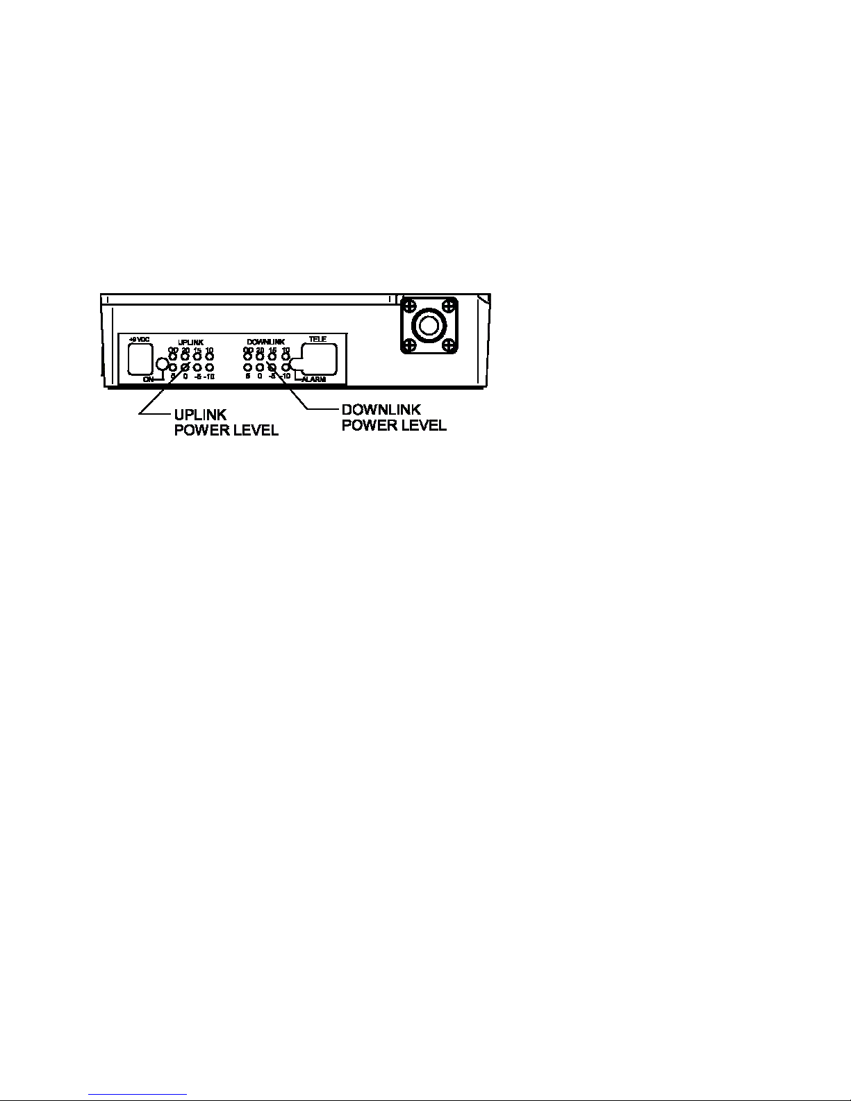
Indicators
The EkoMini is equipped with three LED indicators on the end of the unit which provide the
following information:
Indicator State Description
IM 610179-1, Rev 02
08/25/06 Page 10
On Off No DC Input Power Applied Green DCPower on, normal function Green
Flashing DC Power on, Set up fault-Band Selection
Alarm Off No Alarm
Red Flashing 5 Minute Warning
(See list of alarms) Red Alarm
Uplink RF Power levels per picture below
Downlink RF Power levels per picture below
No RF Uplink Detected; this is a normal state for the uplink RF path. The normal levels of RF
received and amplified from the subscriber unit may be below the -10 dBm detectable level. A
quick check can be made by getting within a few feet of the Rerad Antenna, while watching the
Uplink RF indicator.
Primary Power
The EkoMini with IP Modem operates on AC input voltages of 100 to 240VAC only.
Donor Antenna
This input/output is connected to an antenna, which is directed at the desired cell site.
Rerad Antenna
This input/output is connected to an antenna, which is mounted in the desired area to be
covered. The antenna should be mounted at a location where adequate coverage is provided
for the area desired while EkoMinimizing the potential of subscriber units normally operating
close enough to overdrive the unit.
Serial Number
Each unit has a unique electronic serial number. This number is displayed on the decal on the
unit and is also displayed with the history log when using the modem interconnect.
Installation:
Note 1: Only qualified technicians should perform Installation and system set up. The user is
cautioned that modification or changes to this device not expressly approved by the party
responsible for compliance could void the user's authority to operate this equipment.
Note 2: Manufacturer's rated output power of this equipment is for single carrier operation. For
situations when multiple carrier signals are present, the rating would have to be reduced by 3.5
dBm, especially where the output signal is re-radiated and can cause interference to the

IM 610179-1, Rev 02
08/25/06 Page 11
adjacent band users. This power reduction is to be determined by means of input power or gain
reduction and not by an attenuator at the output device.
AC Systems (EkoMini with IP Modem)
The voltage input range is 100-240VAC, single phase 50-60Hz. Use only a grounded electrical
outlet when connecting the unit to a power source. If you do not know whether the outlet is
grounded, consult with a qualified electrician.
A readily accessible disconnect device that is suitably approved and rated shall be incorporated
into the field wiring.

IM 610179-1, Rev 02
08/25/06 Page 12
User Interface Overview
The IPWMM (IP connected wireless modem module) allows the user to monitor the operation of
the repeater and control some of it’s function remotely. The modem connects through a
CDMA200 network and looks and acts like an IP connection. Once the user knows the IP
address of the modem he/she can connect to the repeater using a laptop connected to the
internet.
The IPWMM also can be connected directly to a computer through an Ethernet Crossover Cable
and will then allow local monitoring and control of the repeater. Password protection is used to
control access to the repeater.
The EkoMini will Auto-Setup on Power Up so it is important to ensure the RF input and output
cables are connected before plugging in the unit to a power source. The IPWMM requires up to
3 minutes to load and connect to the network after power up even though the EkoMini typically
sets up in less than 30 seconds.
List of items and information needed to configure the EkoMini. See the Table below for a list of
items needed.
Item Number EMS Part Number Description
1. -na- EkoMini IPWMM, Site ID or Cascade
Code pre-programmed into the repeater
2. -na- A computer running windows and
Ethernet port (RJ45)
3. -na- Ethernet crossover cable
4. EkoMini User’s Guide
5. -na- A Site ID or Cascade code for the
repeater.
6. -na- The SNMP server IP address. This is
where heartbeats and other SNMP
messages will be sent. The format is
standard IP format, 255.255.255.255
7. -na- The desired heartbeat time in minutes.

IM 610179-1, Rev 02
08/25/06 Page 13
Using A Web Browser to Control the EkoMini
Web Browser Overview
The web browser will allow you to monitor the operation of the EkoMini and configure some of
the parameters. The web interface can be used locally with a computer connected to the
EkoMini or through the wireless modem connection.
Connecting Remotely or through the Ethernet Power
Local Connection
The user must make sure the computer connected locally is configured properly to use the local
ethernet connection. Make sure you are using an Ethernet Crossover cable or the connection
will not work. Connect the ethernet crossover cable from the ethernet port on the computer to
the ethernet port on the IPWMM.
The instructions that follow will show how to set up the computer to interface to the IPWMM.
The instructions are for a computer running Windows XP. The computer must be set up to have
a static IP address. How to do this is explained below.
Setting up Windows XP for Static IP
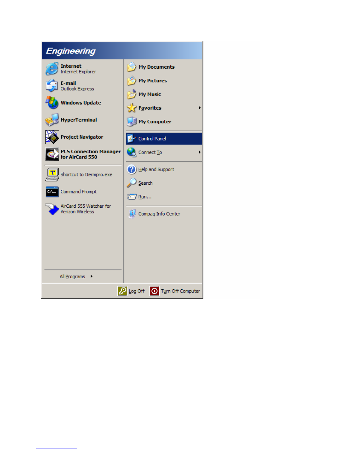
1. Start up the computer and click on the Start button, lower left of the screen.
2. Click on “Control Panel”. See Figure 1.
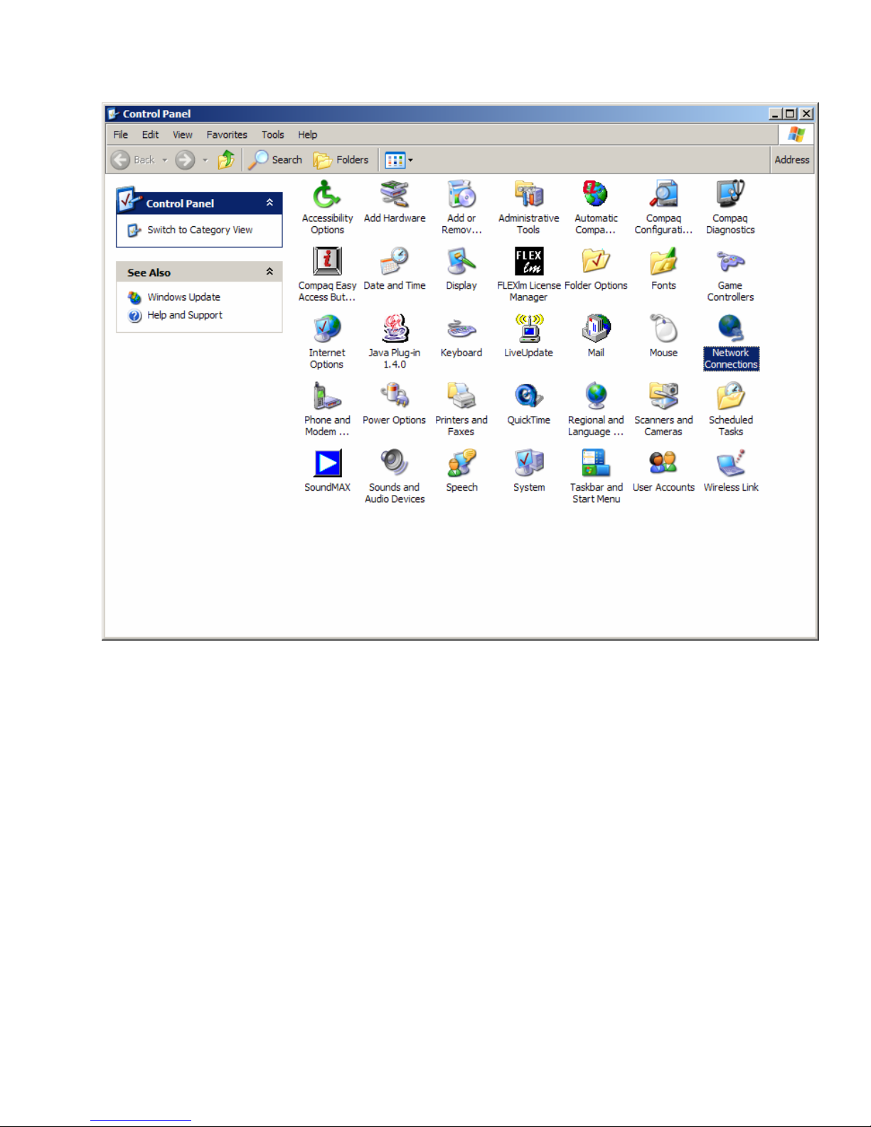
3. In the “Control Panel” window, double click on “Network Connections” See Figure 2
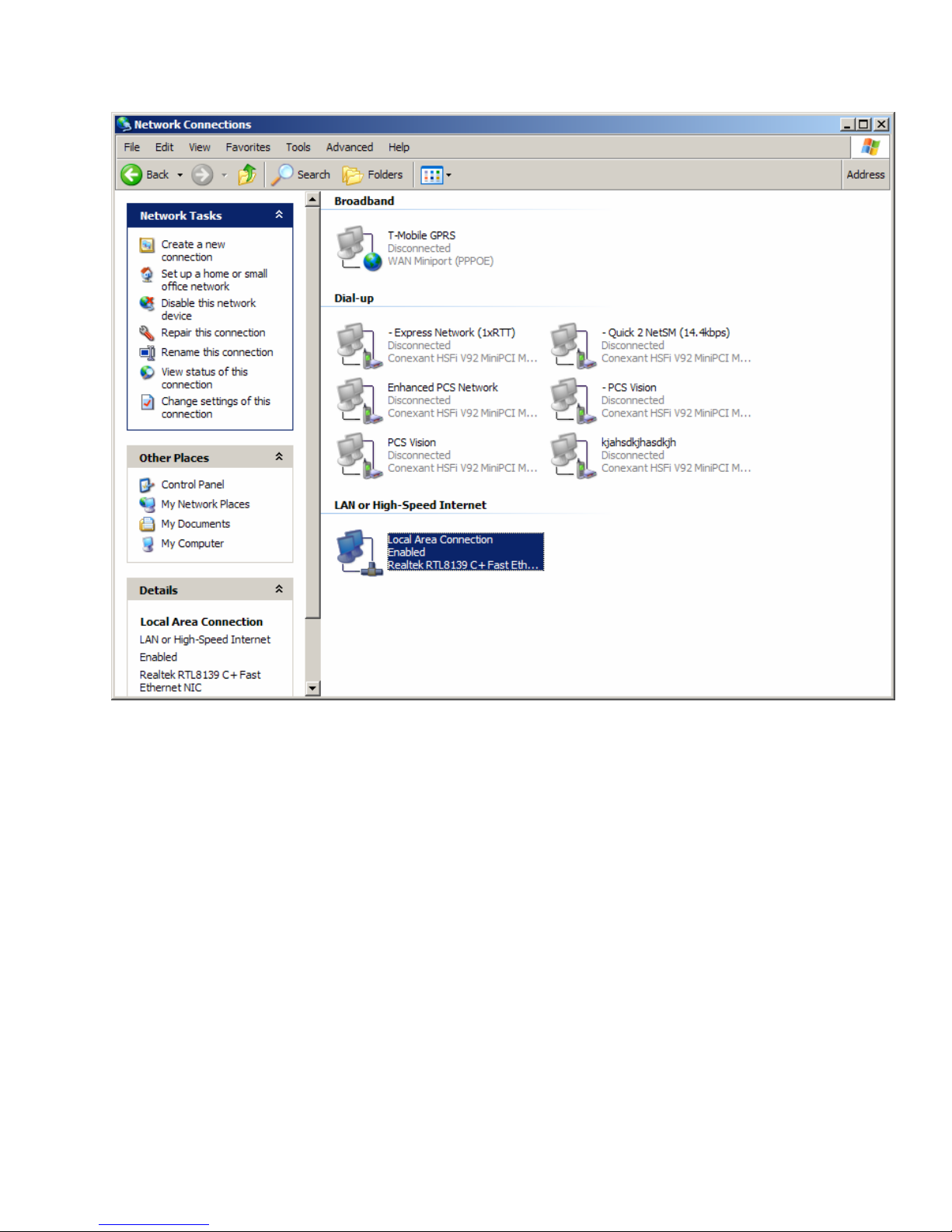
4. In the “Network Connections” window find the Local Area Connection. Move the mouse
over it, left click to highlight it. See Figure 3.
5. Click the right mouse key and select from the menu “Properties”
6. On the “Local Area Connection Properties” window, select “Internet Protocol” and click
on the “Properties” button. See Figure 4.
7. In the “Internet Protocol (TCP/IP) Properties” click on the “Alternate Configuration” tab.
See Figure 5.
8. Make sure the ‘User Configured’ option is selected.
9. Enter the IP address and Subnet Mask as shown in Figure 5.
10. Click the OK button. The computer may take awhile to save the changes.
11. You are ready to connect now.
12. Start an Internet browser session (Explorer or equivalent)
IM 610179-1, Rev 02
08/25/06 Page 14
Figure 1
IM 610179-1, Rev 02
08/25/06 Page 15
Figure 2
IM 610179-1, Rev 02
08/25/06 Page 16
Figure 3

IM 610179-1, Rev 02
08/25/06 Page 17
Figure 4

IM 610179-1, Rev 02
08/25/06 Page 18
Figure 5
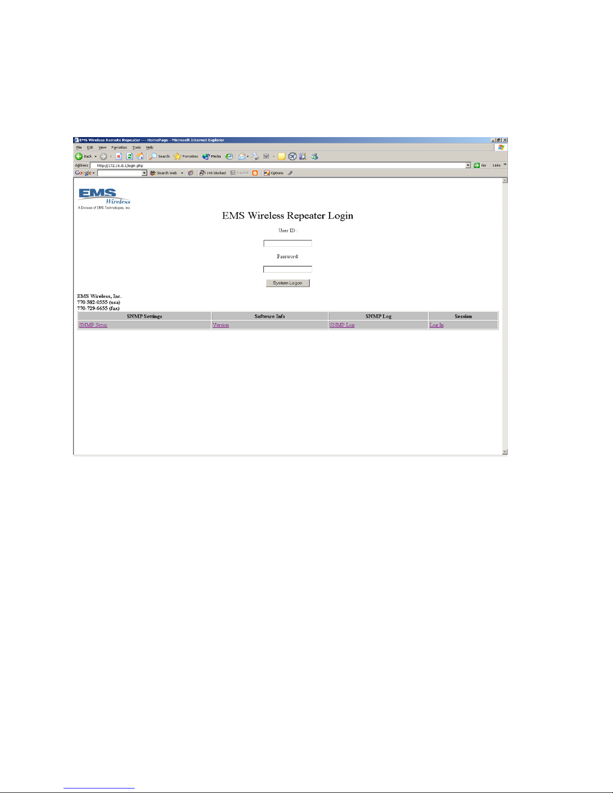
When connecting locally enter http://172.16.0.1 in the browser address bar.
Remote Connection Through the Wireless Modem
You’ll need to find out the IP address of the modem and enter it into the browser address bar.
The wireless service provider needs to supply this address since the addresses are dynamically
allocated. Be sure there are no firewalls that prevent connection. Wireless service providers
usually operate closed networks, so if the EkoMini modem is on one of those the computer
accessing the EkoMini needs to be on that network too.
Pre-Login Access
You can view some of the settings without logging into the EkoMini. The items are described
below.
IM 610179-1, Rev 02
08/25/06 Page 19
Start/Login Page
From this page you can view some of the screens or log in to gain access. We’ll look at what
you can do without logging in.
Other EMS Wireless Repeater manuals


