EMX Industries, Inc. IRB-RET User manual
O P E R A T I N G I N S T R U C T I O N S
Operating Instructions
4564 Johnston Parkway, Cleveland, Ohio 44128
P. 800 426 9912 F. 216 518 9884
www.emxinc.com
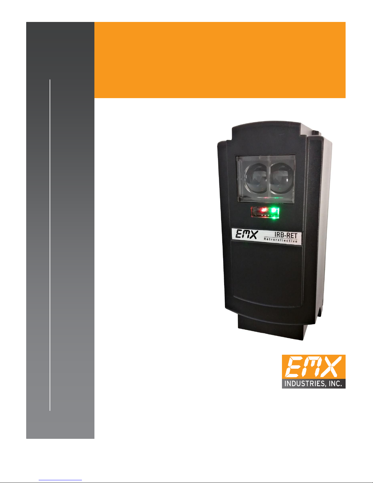
IRB-RET
UNIVERSAL SAFETY
RETROREFLECTIVE PHOTOEYE
U L 3 2 5 - 2 0 1 8 M O N I T O R E D D E V I C E

IRB-RET Operating Instructions 1
Document no. 10300104
Contents
Cautions and Warnings
2
Product Overview
2
Specifications
3
Configuration settings and wiring diagrams
4
Indicators
12
Installation
12
Verification and operation
13
Troubleshooting
14
Ordering Information
14
Accessories
14
Warranty
14

IRB-RET Operating Instructions 2
Document no. 10300104
Cautions and Warnings
1. Read and follow all operating and Installation instructions.
2. Always follow gate operator manufacturer installation instructions regarding
installation of TYPE B1 sensor to the operator.
3. Disable the gate so it is unable to move.
Refer servicing to qualified service personnel.
IMPORTANT:
This product is an accessory or part of a system. Always read and follow the manufacturer’s
instructions for the equipment before connecting this product. Comply with all applicable
codes and safety regulations. Failure to do so may result in damage, injury or death.
Retro-reflective photo-eyes rely on a reflective surface (a reflector) for proper
operation.
In some cases a vehicle with reflective surface at a given distance can act as a
reflector and allow the gate to close on a vehicle.
EMX Industries Inc. assumes no responsibility in this case and all the risks are on the installer,
designer and user of the gate system with a retro-reflective photo-eye.
In case such a risk is not acceptable, EMX Industries Inc. strongly recommends the use of thru-
beam type of a photo-eye.
Product Overview
The IRB-RET retroreflective photo eye is an external entrapment protection device type B1,
non-contact sensor for use with automatic gates and doors. The light beam is near infrared
and pulses at a rate of 300/second (300Hz). Since the reflector directs the beam back to the
photo eye, wiring to the other side of the roadway is not required. The IRB-RET provides a
signal to the gate or door operator that the beam is not obstructed. The operating range is up
to 60ft. The IRB-RET operates over a wide range of 6-40VDC and 12-24VAC (dependent on
configuration selection).
A red alignment indicator on the receiver provides status information at a glance, making set-
up and alignment easy. A green LED indicates power.
The IRB-RET includes 3 selectable operating configurations and provides 5 monitoring options
for compatibility with most operators that accommodate monitored external entrapment
protection devices. The IRB-RET complies with UL325 requirements effective August 1, 2018.
Refer to operator manufacturer’s instructions to assure compatibility.
REFER to operator installation instructions for proper configuration selection

IRB-RET Operating Instructions 3
Document no. 10300104
CONFIGURATION 0 - RELAY OUTPUT, NON-MONITORED and MONITORED
Intended for use with operators that require simple relay contact activation to
indicate beam obstruction. Reference Light ON/Dark ON setting. Jumper
available for compatibility with Normally Open 10K termination operators.
CONFIGURATION 1 –MONITORED, HEARTBEAT 300Hz / 0Hz
Intended for use with operators designed to accept a “heartbeat” form of
monitoring, 300Hz when aligned, no obstruction, 0Hz when beam is obstructed.
CONFIGURATION 2 –MONITORED, HEARTBEAT 300Hz / 2Hz / 0Hz
Intended for use with operators designed to accept a “heartbeat” form of
monitoring, 300Hz when aligned, no obstruction, 2Hz when beam is obstructed,
and 0Hz for a failure.
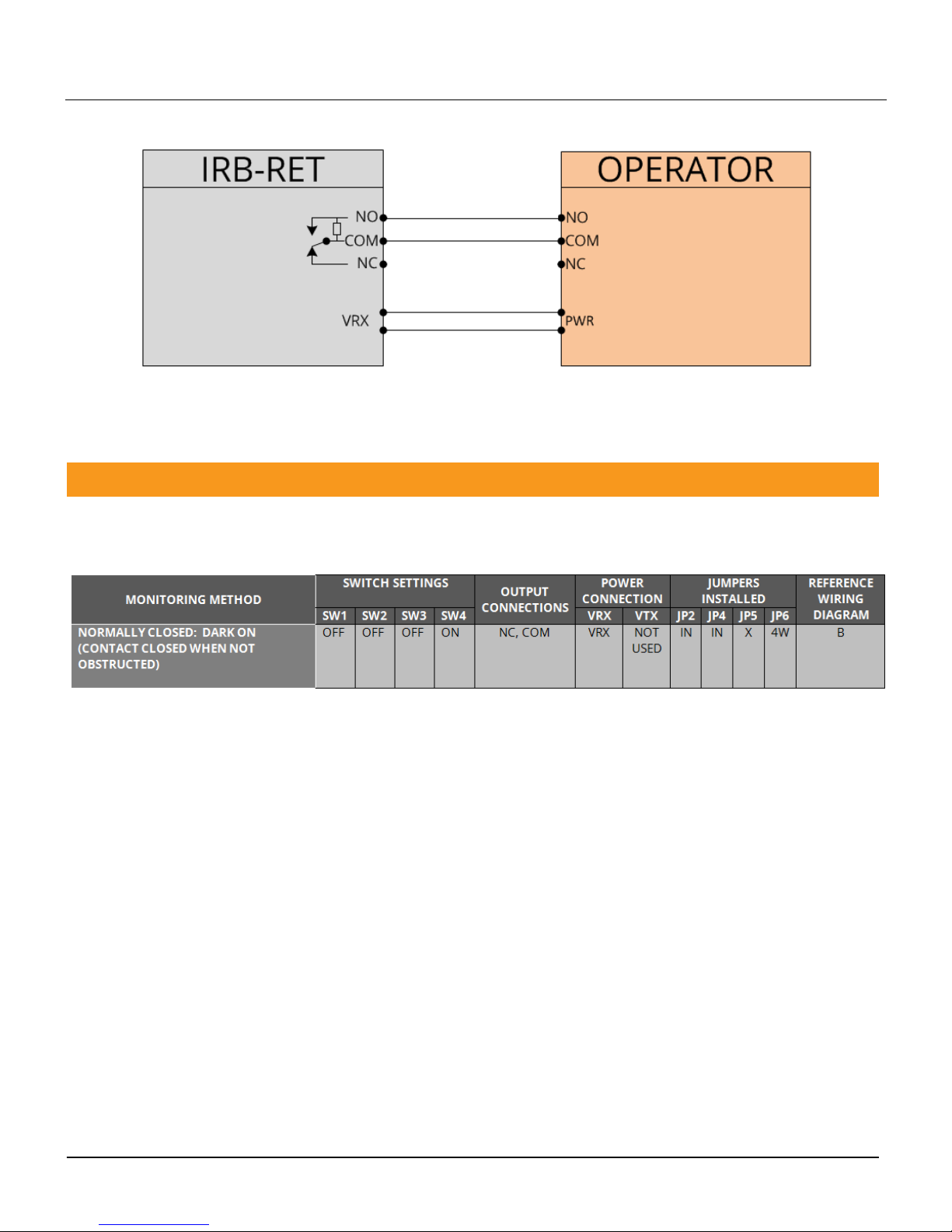
Five monitoring interfaces:
1. Normally closed: Cycle power to the transmitter while monitoring the
receiver contacts for proper operation
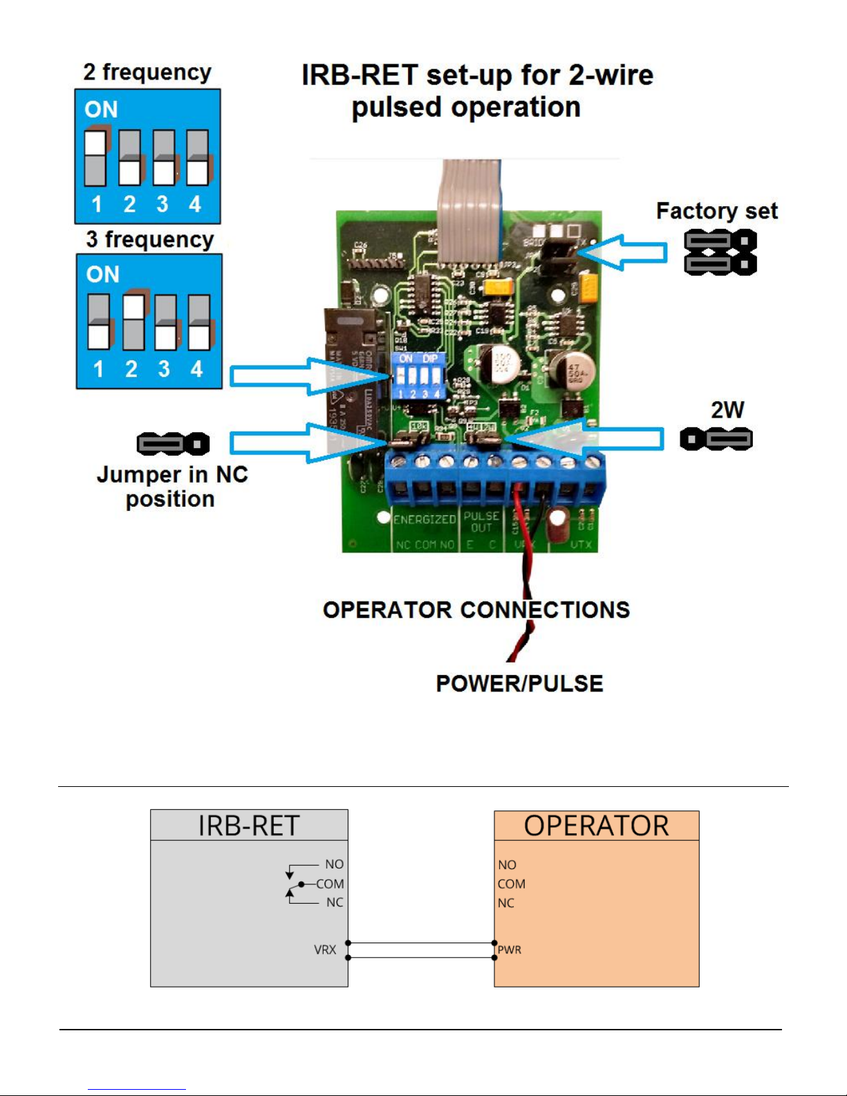
2. Two-wire pulsed (2 freq): Provides 300Hz “heartbeat” unobstructed, 0Hz
obstructed over power supply lines
3. Two-wire pulsed (3 freq): Provides 300Hz “heartbeat” unobstructed, 2Hz
obstructed and 0Hz failure over power supply lines
4. Four-wire pulsed: Provides 300Hz “heartbeat” unobstructed, 0Hz
obstructed over separate connection
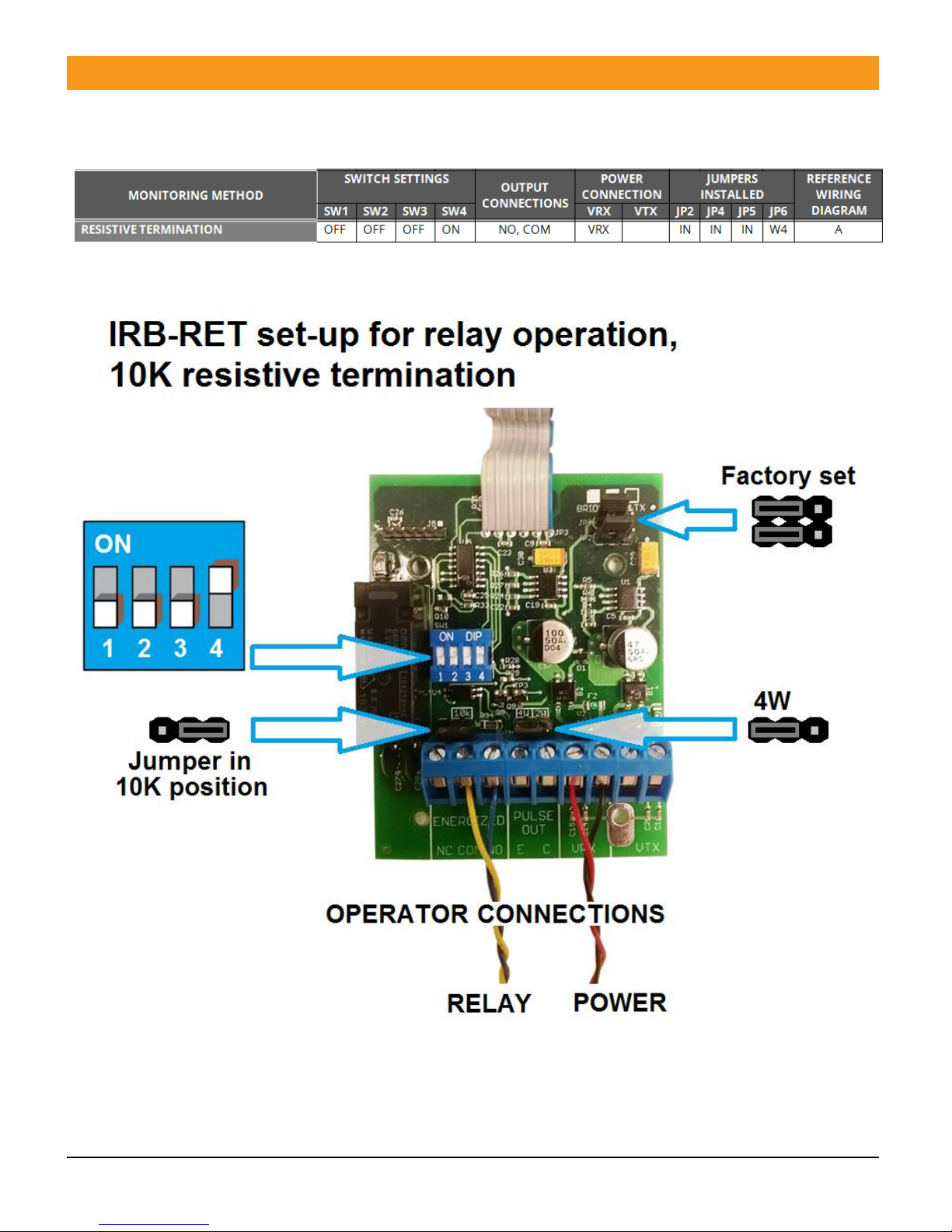
5. Resistive termination: Provides a measurable resistance when unobstructed

IRB-RET Operating Instructions 4
Document no. 10300104
Specifications
Specifications
Operating range
5ft. (1.5m) to 60 ft. (18.3m)
Sensitivity adjustment
Potentiometer
Power indicator
Green LED
Detect indicator
Flashing green LED
Mode selection switch
3 modes: relay output, pulsed (3 frequency), pulsed (2
frequency
Relay output operation
Light ON/dark ON
Relay output
Form C contacts (NO, COM, NC)
Resistive termination
10K ohm across NO contact (jumper selectable)
Power protection
Thermal fuse
Transmitter power cycle
>300mS (for use in configuration 0 Monitored)
Power (see Cautions and Warnings)
6…40VDC, 12…24VAC @ 60 Hz (Configuration 0 RELAY only)
Current (Config. 0)
60mA (relay activated)
Current (Config. 1 & 2)
15mA (12VDC, includes TX and RX wired in parallel)
Operating temperature
-40°…140°F (-40°…60°C)
Environmental
NEMA 4X
Dimensions (L x W x H)
3.1” (79mm) x 2.7” (69mm) x 6.6” (168mm)
Weight
0.7 lbs (320g),
Connections
7 terminals
Configuration Settings and Wiring Diagrams
ABREVIATIONS
DESCRIPTION
VTX
Transmitter power input
VTX
Transmitter power input
VRX
Receiver power input
VRX
Receiver power input
PULSE OUT E
Isolated output emitter (Note 1)
PULSE OUT C
Isolated output collector (Note 1)
NO
Normally Open contact, relay output shown in energized state (power on, no
obstruction)
COM
Relay common
NC
Normally Closed contact, relay output shown in energized state (power on, no
obstruction)
(1) Four-wire output provides an emitter and collector connection to the operator. The emitter is
generally connected to the circuit common (ground) and the collector is typically an open-
collector output using a pull-up resistor to low-voltage DC power.
IRB-RET Operating Instructions 5
Document no. 10300104
RESISTIVE
NOTE: Remove power when changing Configuration settings
NOTE: The relay contacts on the board and the references to them in these Instructions are shown in the
energized state, no obstruction, Dark ON setting.
IRB-RET Operating Instructions 6
Document no. 10300104
WIRING DIAGRAM A
N.C.
NOTE: Remove power when changing Configuration settings
NOTE: The relay contacts on the board and the references to them in these Instructions are shown
in the energized state, no obstruction, Dark ON setting.
X indicates jumper not in 10K position, it is in the storage position, or removed

IRB-RET Operating Instructions 7
Document no. 10300104
WIRING DIAGRAM B

IRB-RET Operating Instructions 8
Document no. 10300104
PULSE AND POWER CYCLE
NOTE: Remove power when changing Configuration settings
(2) Pulsed configurations require current limiting in the operator. The IRB-RET will pulse the
power lines when no obstruction is present.
(3) Four-wire output provides an emitter and collector connection to the operator. The emitter is
generally connected to the circuit common (ground) and the collector is typically an open-
collector output using a pull-up resistor to low-voltage DC power.

IRB-RET Operating Instructions 9
Document no. 10300104
WIRING DIAGRAM C
IRB-RET Operating Instructions 10
Document no. 10300104
WIRING DIAGRAM D

IRB-RET Operating Instructions 11
Document no. 10300104
WIRING DIAGRAM E
IRB-RET Operating Instructions 12
Document no. 10300104
INDICATORS
GREEN
ON
Aligned with reflector, no obstruction
GREEN
Flashing
Beam obstructed or not aligned
GREEN
OFF
No power
RED
ON
Aligned
RED
OFF
Beam obstructed or not aligned
Install the IRB-RET according to instructions from the gate operator
manufacturer. The intent of External Entrapment Protection Device Type
B1 non-contact sensor is to protect a person from being accidentally
injured by the moving gate or door.
DO NOT USE 12-24VAC IN PULSE CONFIGURATIONS.
1. NOTE: If the terminal screw is backed out all the way it may be necessary to apply slight
downward pressure while tightening to re-engage the internal mechanism.
2. Disconnect the IRB-RET from power before installing or servicing the device.
3. Always follow the instructions of the gate operator manufacturer regarding installation of type
B1 sensors on the gate operator. The instructions of the gate operator manufacturer always
supersede any instructions given in this or any other instructions by EMX Industries Inc.
4. Refer to the Configuration settings table for connections based on Configuration and
monitoring method.
5. When using the relay outputs, do not exceed the voltage/current ratings indicated in the
specification table.
6. Install the IRB-RET according to instructions from the gate or door operator manufacturer. The
intent of External Entrapment Protection Device Type B1 non-contact sensor is to protect a
person from being accidentally injured by the moving gate or door.
7. The IRB-RET is housed in a NEMA 4X enclosure. To insure the integrity of the enclosure make
sure the gasket is present, the cover is properly seated and the cover screws are tight. The
wiring to the enclosure must enter via UL Listed watertight fitting such as a strain relief or
watertight conduit connector.
8. The IRB-RET must be powered by Class 2 circuits only, wiring must be segregated from other
circuits or insulation must be provided that is suitable for the highest voltage for those circuits.
Indicators
Installation
IRB-RET Operating Instructions 13
Document no. 10300104
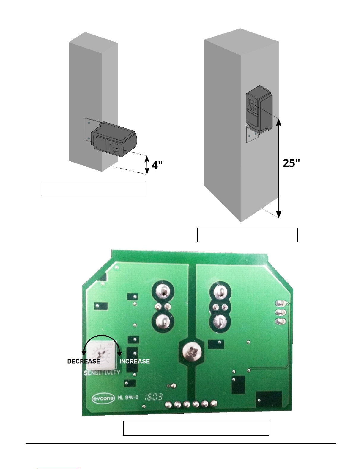
Mounting position for door
Mounting position for gate
LOCATION OF SENSITIVTY ADJUSTMENT

IRB-RET Operating Instructions 14
Document no. 10300104
Alignment instructions:
1. Set sensitivity adjustment to 1/3 of the setting.
2. Hold the reflector and start at 4 to 6 feet away and move the reflector left, right, up and
down in a 2 foot pattern while slowly retreating to the area where the reflector will be
mounted.
Mount the reflector as close to the center of the pattern as possible to assure the
strongest signal. If it is necessary to reposition the photo eye, repeat these steps to
properly position the reflector.
3. If the signal drops out before getting to the desired distance, increase the sensitivity to 1/2 or
3/4 of the range and repeat step 2.
4. Increase sensitivity adjustment to MAX.
Verification and operation
Verify proper operation of the IRB-RET according to instructions from the
gate operator manufacturer. The intent of External Entrapment Protection
Device Type B1 non-contact sensor is to protect a person from being
accidentally injured by the moving gate or door.
1. Verify that the IRB-RET and reflector are in line of sight and apply power.
2. Place an obstruction (ex. hand) between the IRB-RET and the reflector. The green LED on the
receiver is flashing and the red LED turns off. Check the operator control board and verify that
the safety input is actuated.
3. Remove the obstruction and green LED and red LED will turn on.
4. If the IRB-RET indicates an obstruction when there is no obstruction, increase the sensitivity by
adjusting the SENSITIVITY pot clockwise and carefully verify alignment with the reflector.
5. Follow gate/door manufacturer’s installation instructions and safety checks to verify that the
IRB-RET is operating properly.

IRB-RET Operating Instructions 15
Document no. 10300104
Troubleshooting
Symptom
Possible cause
Solution
Does not detect obstruction
of beam
Signal is reflecting off another
surface
Check area for highly reflective
surfaces
Green LED flashes
continuously (indicating an
obstruction when an
obstruction is not present)
Sensitivity too low
Photoeye is not aligned with
the reflector
Adjust SENSITIVITY pot
clockwise
Check alignment, verify
operation with reflector at 10ft
Photoeye activates but does
not transmit signal to
operator
Faulty connection between
photoeye and operator
control input
Verify all wires and terminal
connections

IRB-RET Operating Instructions 16
Document no. 10300104
Ordering Information
IRB-RET Retroreflective photoeye, Includes REFLECTOR-O-EX and mounting
bracket with hardware
Accessories
REFLECTOR-O-HD Plastic protective hood for reflector
IRB-RET-HD Steel protective hood for photoeye
Warranty
EMX Industries Incorporated warrants all products to be free of defects in materials and
workmanship for a period of two years under normal use and service from the date of
sale to our customer. This warranty does not cover normal wear and tear, abuse, misuse,
overloading, altered products, damage caused by incorrect connections, lightning
damage, or use other than intended design.
There is no warranty of merchantability. There are no warranties expressed or implied or
any affirmation of fact or representation except as set forth herein.
EMX Industries Inc. sole responsibility and liability, and the purchaser’s exclusive remedy
shall be limited to the repair or replacement at EMX Industries option of a part or parts
found not conforming to the warranty. In no event shall EMX Industries Inc. be liable for
damages, including but not limited to damages resulting from non-conformity, defect in
material or workmanship.
Effective date: January 1st, 2002

IRB-RET Operating Instructions 17
Document no. 10300104
4564 Johnston Parkway
Cleveland, Ohio 44128
United States of America
www.emxinc.com
Technical Support: (216) 834-0761
Sales: (216) 518-9888
Fax: (216) 518-9884
Revision 1.9
3-1-18
Table of contents
Other EMX Industries, Inc. Accessories manuals

Popular Accessories manuals by other brands


MB QUART
MB QUART MM-1 operating instructions

Silvercrest
Silvercrest SSHK 100 B2 operating instructions

Rocket Fish
Rocket Fish InvisiShell RF-GWU1301 Guide d'installation rapide

Chef's Choice
Chef's Choice 476 Instructions for use

REV
REV Funk-Gong Orchestra DB400AC operating instructions

Tripp Lite
Tripp Lite UPB-05K2-APL owner's manual