EMX Industries, Inc. IRB-325 User manual
I
IR
RB
B-
-3
32
25
5™
I
In
nf
fr
ra
ar
re
ed
d
P
Ph
ho
ot
to
oc
ce
el
ll
l
Operating Instructions
This product is an accessory or part of a system. Always read and follow the
manufacturer’s instructions for the equipment you are connecting this product to. Comply with
all applicable codes and safety regulations. Failure to do so may result in damage, injury or
death!

IRB-325 Instructions 2
Document no. REV 1.0 Date 10/25/2007

IRB-325 Instructions 3
Document no. REV 1.0 Date 10/25/2007
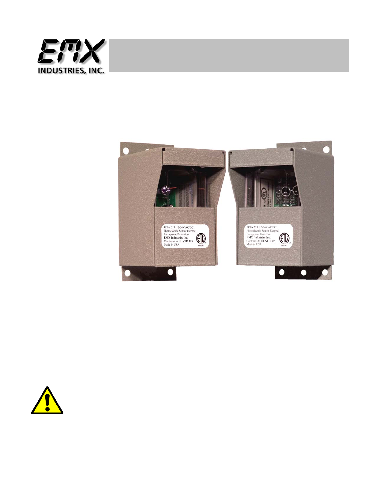
Product Overview
The IRB-325 conforms to the UL325 standard when used with the powder coated steel
hoods. Registration reference number 9901994. The IRB-325 photocell is used as an
external entrapment protection device type B1 non-contact sensor for use with automatic gate
and door openers.
The IRB-325 transmitter and receiver have a line of site range of up to 65 feet. The IRB-325
operates on 12 VDC to 24 VAC and draw 150 mA maximum.
The IRB-325 receiver is activated whenever anything interrupts the beam from the
transmitter, triggering the relay output to change state and send a signal to the operator that
there has been an interruption.
Technical Specifications
Controls, Indicators and Connections
Transmitter Receiver
The IRB-325 is an external entrapment device Type B1 non-contact sensor for use
with automatic gate operators. If the IRB-325 is used as the primary entrapment
protection device it must be monitored for presence and fault condition.
Power Supply 12 Volts Dc to 24Volts AC
Power Supply Tolerance +/- 20%
Current Draw 150 mA maximum
Housing Material UL and CSA Type 4, 4X, 3, 3R, 12, 13 rating and powder coat steel hood
Relay Type Type C Rating 1A @ 30 VDC
Temperature Range -40oF to 170oF
Connector Screw terminal isolated contact (2) transmitter (5) receiver
Power Indicator Green LED
Detect Indicator Red LED
Dimensions H=5.03 in, W=3.06 in, D=3.02 in
Range 6 feet to 65 feet line of sight
Power LED
Green SMT glows when power is applied
Power LED
Green SMT glows when power is applied
Connections Screw terminal
2 position for power source
Connections Screw terminal
5 position for power and controls
Detect LED
(2) Red SMT LEDs glow on detection

IRB-325 Instructions 4
Document no. REV 1.0 Date 10/25/2007
Installation
1. Disconnect the IRB-325 from power before installing or servicing the device.
2. Always follow the instructions of the gate operator manufacturer regarding installation
of type B1 sensors on the gate operator. The instructions of the gate operator
manufacturer always supersede any instructions given in this or any other instructions
by EMX Industries Inc.
3. The IRB-325 has to be powered by 12V – 24V AC/DC 150mA power supply.
4. Do not connect the IRB-325 output to loads higher than 1A @ 30V AC/DC.
5. Connect power to terminals 1 and 2 on IRB-325 transmitter marked “TX” polarity is
not important.
6. Connect power to terminals 4 and 5 marked “power input” on the IRB-325 receiver,
marked “RX” polarity is not important.
7. For operators that require normally closed contact for entrapment protection, connect
terminals 1 (NC) and 2 (COM) to the designated terminals in the gate operator.
8. For operators that require normally open contact for entrapment protection, connect
terminals 2 (COM) and 3 (NO) to the designated terminals in the gate operator.
9. Install the IRB-325 according to instructions from the gate operator manufacturer. The
intent of External Entrapment Protection Device Type B1 non-contact sensor is to
protect a person from being accidentally injured by the moving gate.
10.The IRB-325 is housed in a NEMA 4X enclosure. To insure the integrity of the
enclosure make sure the covers are attached and closed tight with the help of four
plastic screws provided. The wiring to the IRB-325 Enclosure has to enter via
watertight strain relief or watertight conduit connector.
11. The IRB-325 must be powered by Class 2 circuits only, wiring must be segregated
from other circuits or insulation must be provided that is suitable for the highest
voltage for those circuits.
IRB-325 Instructions 5
Document no. REV 1.0 Date 10/25/2007
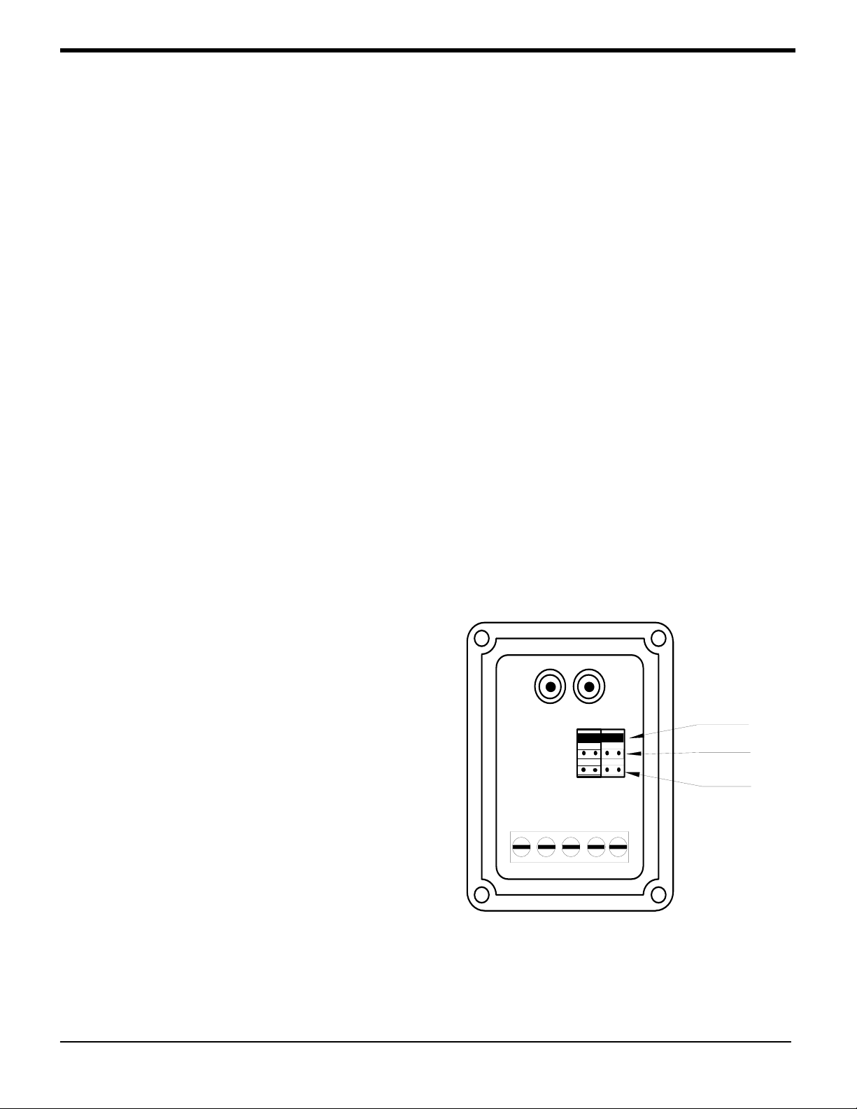
HIGH
MED
LOW
N/C COM N/O PWRPWR
IRB-325 RX
Operational settings explained
WARNING: To reduce the risk of sever injury or death
1. Read and follow all operation instructions.
2. Always follow gate operator manufacturer installation instructions regarding
installation of Type B1 sensor to the operator.
3. Disable the gate so it is unable to move.
4. With the IRB-325 mounted in place and powered, make sure the transmitter “TX” is in
line of sight of the receiver “RX”.
5. Introduce an obstruction in form of a hand between the IRB-325 transmitter and
receiver. Two Red LED’s on the receiver have to turn on. Check the operator control
board that the safety input is actuated.
6. Remove the obstruction and the Red LED’s in receiver will turn off.
7. Should the IRB-325 fail to recognize the obstruction lower the sensitivity by moving
jumpers J1 and J2 to a lower position.
8. Should the two Red LED’s be turned on while there is no obstruction increase the
sensitivity by moving jumpers J1 and J2 to a higher position.
1 2 3 4 5

IRB-325 Instructions 6
Document no. REV 1.0 Date 10/25/2007
TROUBLE SHOOTING GUIDE
Symptom Possible cause Solution
Does not detect interruption Sensitivity too high
Signal is reflecting off another
surface
Move jumpers J1 and J2 to a
lower position
Check area for highly reflective
surfaces
Red detect LED stays on Sensitivity too low
Transmitter does not have power
Receiver does not “see”
transmitter
Move jumpers J1 and J2 to a
higher position
Check power source for
transmitter
Make sure transmitter and
receiver have line of sight
alignment
Receiver activates but does not
transmit signal to operator Faulty connection between
receiver and operator control
input
Check wires and terminal
connections to make sure they
are good
IRB-325 Instructions 7
Document no. REV 1.0 Date 10/25/2007
Ordering Information
IRB-325 Infrared photocell includes transmitter and receiver
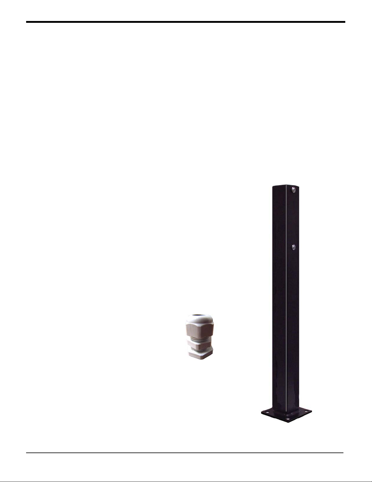
Accessories
IRB-325-HD Set of 2 powder coated steel protective hoods
required for UL-325
IRB-325-PT Mounting post 2 in x 2 in x 2 ft black powder coat
IRB-325-SP Watertight strain relief for use with interconnection cords.
I
IRB-325-SP
IRB-325-PT

IRB-325 Instructions 8
Document no. REV 1.0 Date 10/25/2007
4564 Johnston Parkway
Cleveland, Ohio 44128
United States of America
WEB http://www.emxinc.com
E-mail [email protected]
Telephone (216) 518-9888
Fax (216) 518-9884
Table of contents
Other EMX Industries, Inc. Accessories manuals

Popular Accessories manuals by other brands

NAPCO
NAPCO DUAL TECH GEMC-BSLC-DT-L installation instructions

RadonTec
RadonTec AlphaFreshbox 200 WiFi manual

Soehnle
Soehnle VALENCIA operating instructions

Pfannenberg
Pfannenberg DTS series Operating and installation instructions

Klarstein
Klarstein 10033435 manual

Husqvarna
Husqvarna WL 8i quick start guide


