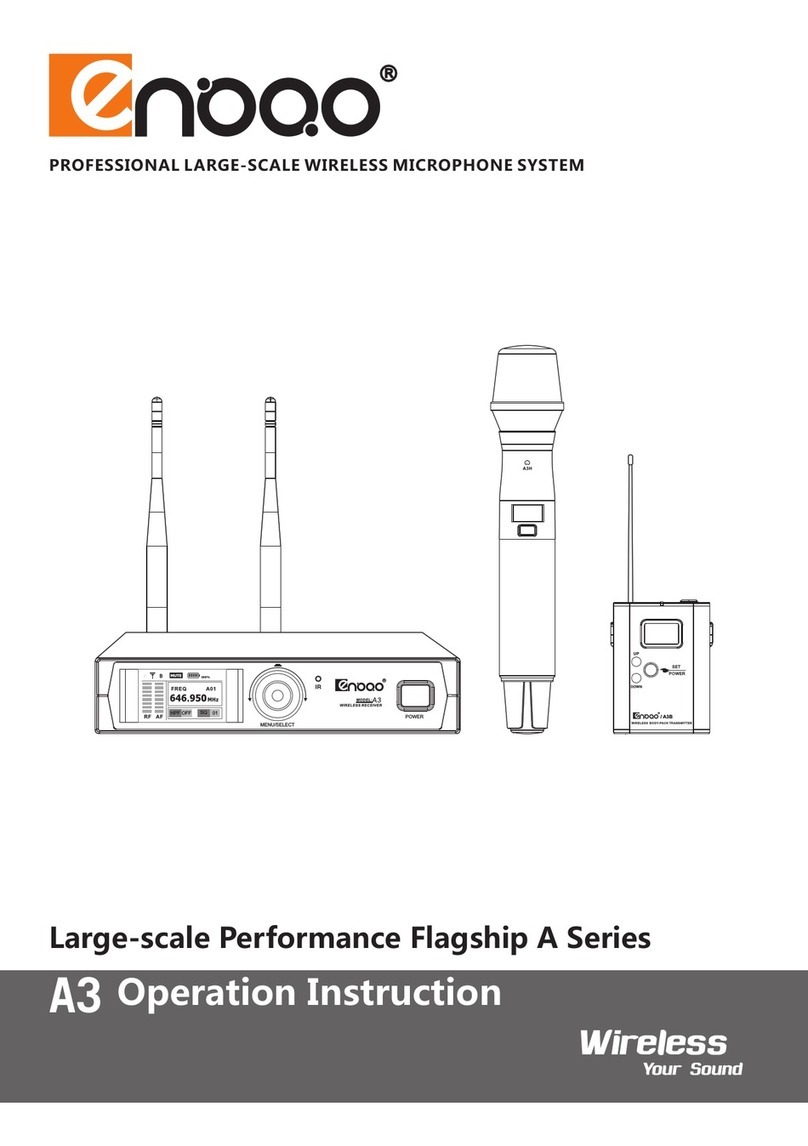
ENBAO A Series User manual

FOUR CHANNELS TURE DIVERSITY WIRELESS SYSTEM
Wireless
Your Sound
A4ws
LARGE-SCALE PERFORMANCE FLAGSHIP A SERIES
OPERATION INSTRUCTION

1
CONTENT
2
3
5
6
7
9
10
11
17
18
19
20
21
22
Safe Information...................................................
Product Introduction............................................
System..................................................................
Receiver Diagram.................................................
Transmitter Diagram.............................................
Beltpack Transmitter Microphone Installation......
Overall Display.....................................................
Receiver Operation Instruction............................
Suggestion And Tips............................................
Setting Frequency................................................
Rack Mount..........................................................
Antenna Distributor
(optional)Connection Diagram.............................
Simple Fault Process...........................................
Specification.........................................................

2
SAFEINFORMATION
1.Read these instructions.
2.Keep these instructions.
3.Heed all warnings.
4.Follow all instructions.
5.Do not use this apparatus near water.
6.Clean with dry cloth only.
7.Do no block any ventilation openings. lnstallin accordance with the manufacturer's
instructions.
8.Do not install near any hear sources such as: radiators, stoves or other apparatus
(including amplifier)that produces heat.
9.Protect the power cord from being walked on or pinched particularly at the plugs,
convenience receptacles, and at the point where they exit from the apparatus.
10.0nly use attachments/accessories specified by the manufacturer.
11.Unplug the apparatus during lightening storms , or when unused for long periods of time.
12.Refer all servicing to qualified personnel. Service is required when the apparatus has
been damaged in any way ,such as power supply cord or plug is damaged , liquid has
been spilled or objects have fallen into the apparatus has been exposed to rain or moisture,
does not operated normally, or has been dropped.
13.This appliance shall not be exposed to dripping or splashing water and that no subject
filed with liquid such as vases shall be placed on the apparatus.
14.Caution-to prevent electrical shock, match wide blade plug wide slot fully insert.
15.Please keep a good ventilation environment around the entire unit.
16.Batteries(battery pack or batteries installed)shall not be exposed to excessive heat such
as sunshine, fired or the like.

3
PRODUCTION INTRODUCTION
Thanks for purchasing our professional models A4ws with excellent performance ,hard
structure and stable operation. Professional flagship A series wireless system using world
class RF&AF dedicated chip, full color TFT display screen. Bodypack transmitter is compatible
with Bass 20Hz and large dynamic instrument. We are devoted to the special design with our
many patents .
Large-scale Flagship Professional A Series Wireless Microphone
Features:
1.Design for large-scale show, lecture and art and sport activities.
2.Front-panel adopt full-color TFT display screen.
3.RFIS wireless real time intelligent control management system.
4.Rotary bottom control.
5.Pilot frequency squelch technology delete wireless RF interference when transmitter closed.
6.Receiver display battery of transmitter.
7.Lock function avoid wrong operation.
8.Anti-interference frequency can be set and changed, up to 20 sets can be used in the same
frequency range without interference.
9.Receive signal automatically, eliminate break signal, increased receive distance and stability.
10.Optimize PLL synthesizer and microprocessor technology.
11.Auto Scan function show the frequency environment of whole frequency range which can be
better to know the situation and select the good channel.
12.10 level receive sensitivity, adjust SQ for different environment.
13.Metal case, elegant design.
14.Transmitter use a pair of AA battery.

4
RFIS Radio Frequency Real Time Sync Control
1.All function can be control in the receiver without close to the receiver once turn on the
transmitter.
2.Intelligent adjust power automatically, system adjust transmit power automatically according
to the environment, ensure stable transmitting distance and reduce electricity interference
and battery consumption.
3.Frequency sync automatically, press button to make connection after scan free frequency.
4.End user can adjust transmitter pickup sensitivity by checking receiver dynamic situation
according to different environment.
5.User can send out the stop order to transmitter by control receiver, including the function of
turn on/off and mute.
6.User can send out the temporary rest, close frequency signal and power amplifying circuit
order to specific number transmitter by control receiver.
This device have same frequency range for selection and have same pre-set frequency
channel system.
Transmit circuit can be into standby situation quickly
Multi-parallel transmit circuit without interference on each other.
FrequencySystem
400 500 700 800600
Super frequency have 5 different frequency range for AF transmission, each one have 1200 to
2400 flexible frequency, receiver can select the frequency from above range:
Each frequency range(A-J)have 10 frequency group , each group have 14 channel:
Group A~J
Channel 1~14
Group A pre-set group
Group B pre-set group
Group J pre-set group
Channel 1 pre-set channel
Channel 2 pre-set channel
Channel 14 pre-set channel
Range A:
470~500
Range B:
518~548
Range C:
606~668
Range EF:
740~790
Range G:
795~825

5
MUTERx01 G/ CH A 01 T xOff MU TE
Rx02 G/ CH A 02 T xOff MU TE
Rx03 G/ CH A 03 T xOff MU TE
Rx04 G/ CH A 04 T xOff MU TE
SYSTEM
(Receiver)
(Handheld transmitter)
(optional)
(Antenna)
(Audio cable) (Guitar cable) (Short rack mount) (User manual)
(Beltpack transmitter) (Lavalier Mic)
(Headset Mic)
(Power adapter) (Power cable)
FOUR CHANNELS DIVERSITY WIRELESS SYSTEM
Wireless
Your Sound
A4ws
LA RG E-S CA LE P ERF OR MA NC E FL AG SH IP A S ER IES
OP ER ATI ON I NS TR UC TI ON

6
MUT ERx0 1 G/CH A0 1 Tx Off M UT E
Rx0 2 G/CH A0 2 Tx Off M UT E
Rx0 3 G/CH A0 3 Tx Off M UT E
Rx0 4 G/CH A0 4 Tx Off M UT E
2 13456
RECEIVERDIAGRAM
ReceiverFrontPanel
1.Power switch
Turn on/off receiver
Stop input and return back
2.W.Sync Button
When select frequency for one channel, short-press the button to
sync connection
Long-press the button to sync connecting four channels together
automatically
3.Rotary Function Knob
Press rotary knob
Rotate rotary button
Open the menu interface
Select the item
Store setting and return to main interface
Lock
Select channel setting interface
Switch to last and next item
Change each item
4.Full Color TFT Display Screen
Display specification
5.Channel 1To 4 AF And RF Indicator Light
6.RF Intelligent Real Time Sync Antennas
2.4GHz antenna

016 0 7 1 4 1 5 7 8 9
恩宝电子有限公司
WIRELESS SYSTEM:A4 ws
RECEIVER MODEL: A4ws R
Made in china
FR E Q : 6 3 8 -6 6 8 M H z
BA LA NC ED -D B AL AN CE D- C BA LA NC ED -B B AL AN CE D- A
DC I N
UNBA LANC ED
12 ~1 5V /1 50 0m A
AN T A
RF I N
ANTB
DC O UTDC I N/OU T
12 ~1 5V /1 50 0m A
RF I N
AN T A
AN TB
RF O UT RF O UT
12~15V/1500mA
DC O UT
12 ~1 5V /1 50 0m A
1233334521
7
ReceiverBackPanel
1.RF Antenna Input Socket
Apply for antenna A and antenna B
2.RF Cascade Connection
Transfer RF signal from antenna A and Antenna B to extra receiver
3.AF Balanced Output
XLR balanced connector
4.AF Mixed Output
1/4"unbalanced connector
5.Power Supply Socket
Apply to external direct current 12V-15V/1500mA
TRANSMITTERDIAGRAM
HandheldMicrophone
1.Metal Microphone Grill
2.Indicator Light
Keep lighting when turn on the mic
Light flashing when mute
3.Power/Mute Switch Button
Long-press turn on/off mic
Short press to mute
Short press to cancel mute
Long press 3 seconds into connecting
when mic is turn off
4.Mic Tube
(Hold the mic far away from bottom of
mic tube)
5.Battery Compartment
Put 1.5V*2 batteries
6.Transmitter Antennas

8
MUTE OPEN
HandheldMicrophone
1.Metal Microphone Grill
2.Indicator Light
Keep lighting when turn on the mic
Light flashing when mute
3.Power/Mute Switch Button
Long-press turn on/off mic
Short press to mute
Short press to cancel mute
Long press 3 seconds into connecting
when mic is turn off
4.Mic Tube
5.Battery Compartment
Put 1.5V*2 batteries
6.Transmitter Antennas
BodypackMicrophone
1.AF Input Socket
Push switch to mute or open to
setting mute or unmute
2.Mute Switch Button
Showing power on/off
3.Power Light
5.Power Switch
4.Antennas
6.Battery Compartment
Put 1.5V*2 batteries
(Hold the mic far away from bottom of
mic tube)

9
TONE
TONE
VOLUME
BELTPACK TRANSMITTER MICROPHONE INSTALLATION
1.Slide down the cover then put into the two pieces
1.5V battery if LED lights up, it means install correct
and power on.
2.Lavalier Microphone
Clamping the microphone to tie or collar,
then connecting the microphone plug to
beltpack output socket and finished
installation.
3.Headset Microphone
Connecting the
microphone plug to
beltpack output socket
and finish installation.
4.Guitar Cable Connection
Plug the guitar cable into bodypack ,
plug the other side of cable into pickup
connector.
Be Careful To Damage Hearing And Equipment!
Receiver have a big noise when plug and pull out the the connecting
cable during install bodypack. Turn down volume before installation.
High noise will damage hearing and overload loudspeaker.

10
①
⑥
② ③ ④
⑤
Rx02
Rx01 G/CH A01 TxOff MUTE
TxOn
Rx03 TxOn MUTE
Rx04 TxOn MUTE
615.750
635.750
667.500
OVERALLDISPLAY
Display receiver specification and the important information of receiver and transmitter
operation status.
Display RX/TX Explanation
1.Channel Receiver
Receiver
Receiver
Receiver/transmitter
Transmitter
Transmitter
2.Group
3.Transmitter status
4.Mute
5.Battery
6.Antenna
Pre-set channel number RX01-RX04
Pre-set group number
Display transmitter turn on/off
AF signal mute
Display battery volume
Antenna input A/B be activated

11
POWE R
Rx02
Rx01 TxOff MUTE
TxOff
Rx03 TxOff MUTE
Rx04 TxOff MUTE
6 2 0 . 0 7 5
6 3 5 . 7 5 0
6 6 7 . 5 0 0
MUTE
6 1 5 . 7 5 0
A
Group
RX01
Channel
Freq
Scan
TxGain
Group
RX02 RX03 Rx04
A
Group
RX01
Channel
Freq
Scan
TxGain
Group
RX02 RX03 Rx04
A
Group
RX01
Channel
Freq
Scan
TxGain
RX02 RX03 Rx04
Group
Group
RX01
Channel
Freq
Scan
TxGain
RX02 RX03 Rx04
Group
A
Group
RX01
Channel
Freq
Scan
TxGain
RX02 RX03 Rx04
Group
C
POWE R Rx02
Rx01 G/CH C05 TxOff MUTE
TxOff
Rx03 TxOff MUTE
Rx04 TxOff MUTE
6 2 0 . 0 7 5
6 3 5 . 7 5 0
6 6 7 . 5 0 0
MUTE
POWE R
RXOPERATIONINSTRUCTION
Turn on/off receiver
Long press power switch button, receiver display information.
Long press power switch button again, receiver turn off.
Group setting
Press rotary button into menu interface.
Rotate rotary button to select channel from R01 to R04.
Press rotary button to confirm(select Rx01 to be sample).
Rotate rotary button to group.
Press rotary button to select group.
Rotate rotary button, select group A to J.
Press button confirm and store.
Press POWER button return.
(Sync connecting again when change frequency each time)

12
Ghannel
RX01
Freq
Scan
TxGain
RX02 RX03 Rx04
Group
01
Channel
A
Group
RX01
Channel
Freq
Scan
TxGain
Group
RX02 RX03 Rx04
A
Group
RX01
Channel
Freq
Scan
TxGain
Group
RX02 RX03 Rx04
POWE R Rx02
Rx01 G/CH C09 TxOff MUTE
TxOff
Rx03 TxOff MUTE
Rx04 TxOff MUTE
6 2 0 . 0 7 5
6 3 5 . 7 5 0
6 6 7 . 5 0 0
MUTE
POWE R
Ghannel
RX01
Freq
Scan
TxGain
RX02 RX03 Rx04
Group
09
Channel
Ghannel
RX01
Freq
Scan
TxGain
RX02 RX03 Rx04
Group
Channel
05
RX01
Scan
TxGain
RX02 RX03 Rx04
Group
Channel
A
Group
RX01
Channel
Freq
Scan
TxGain
Group
RX02 RX03 Rx04
A
Group
RX01
Channel
Freq
Scan
TxGain
Group
RX02 RX03 Rx04
POWE R
POWE R
Freq 615.750MHz
Frequency
RX01
Scan
TxGain
RX02 RX03 Rx04
Group
Channel
Freq
Frequency
RX01
Scan
TxGain
RX02 RX03 Rx04
Group
Channel
Freq
Frequency
Rx02
Rx01 TxOff MUTE
TxOff
Rx03 TxOff MUTE
Rx04 TxOff MUTE
6 2 0 . 0 7 5
6 3 5 . 7 5 0
6 6 7 . 5 0 0
MUTE
6 1 5 . 8 0 0
615.800MHz615.750MHz
Channel setting
Press rotary button into menu interface.
Rotate rotary button select channel from R01 to R04, press
rotary button to confirm selection.
Rotate rotary button select channel, press rotary button to
confirm, then number flashing.
Rotate rotary button, select from 01 to 14, press button to
confirm selection.
Press POWER button return.
Frequency setting
Press rotary button into menu interface.
Rotate rotary button select channel from R01 to R04, press
rotary button ton confirm selection.
Rotate rotary button select Freq, press rotary button to confirm,
now number will flash.
Rotate rotary button to adjust frequency with 25KHz stepping,
press button to confirm selection.
Press POWER button return.
(Sync connecting again when change frequency each time)
(Sync connecting again when change frequency each time)

13
RX01
Freq
TxGain
RX02 RX03 Rx04
Group
Channel
A
Group
RX01
Channel
Freq
Scan
TxGain
Group
RX02 RX03 Rx04
A
Group
RX01
Channel
Freq
Scan
TxGain
Group
RX02 RX03 Rx04
POWE R
POWE R
Scan Scan
Frequency
90dB 90dB
606.000 MHz
Rx02
Rx01 TxOff MUTE
TxOff
Rx03 TxOff MUTE
Rx04 TxOff MUTE
6 2 0 . 0 7 5
6 3 5 . 7 5 0
6 6 7 . 5 0 0
MUTE
6 0 6 . 0 0 0
A
Group
RX01
Channel
Freq
Scan
TxGain
Group
RX02 RX03 Rx04
A
Group
RX01
Channel
Freq
Scan
TxGain
Group
RX02 RX03 Rx04
RX01
Scan
RX02 RX03 Rx04
Group
Channel
Freq
TxGain
Tx Gain
+ 0 dB
RX01
Scan
RX02 RX03 Rx04
Group
Channel
Freq
TxGain
Tx Gain
+ 0 dB
RX01
Scan
RX02 RX03 Rx04
Group
Channel
Freq
TxGain
Tx Gain
+10 dB
Scan and select frequency
Press rotary button into menu interface.
Rotate rotary button select channel from R01 to R04, press
rotary button to confirm selection.
Rotate rotary button to Scan, press rotary button start to scan
(check picture 4) and search the free frequency automatically,
(check picture 5) display available frequency.Now rotate rotary
button to select free frequency.
Press POWER button return.
Transmitter gain setting
Press rotary button into menu interface.
Rotate rotary button select channel from R01 to R04, press
rotary button to confirm selection.
Rotate rotary button select TX Gain, press rotary button
confirm selection, then number flashing.
Rotate rotary button to select from +0dB to +10dB, press rotary
button confirm selection.
Scaning frequency Display available frequency after scanning

14
A
Group
RX01
Channel
Freq
Scan
TxGain
Group
RX02 RX03 Rx04
A
Group
RX01
Channel
Freq
Scan
TxGain
Group
RX02 RX03 Rx04
RX01
Squelch
RX02 RX03 Rx04
TxState
Tx State
OFF
TxLock
RxLock
Back
RX01
Squelch
RX02 RX03 Rx04
TxState
Tx State
TxLock
RxLock
Back
OFF
RX01
Squelch
RX02 RX03 Rx04
TxState
Tx State
TxLock
RxLock
Back
ON
POWE R
Rx02
Rx01 G/CH C09 TxOn
TxOff
Rx03 TxOff MUTE
Rx04 TxOff MUTE
6 2 0 . 0 7 5
6 3 5 . 7 5 0
6 6 7 . 5 0 0
MUTE
POWE R
A
Group
RX01
Channel
Freq
Scan
TxGain
Group
RX02 RX03 Rx04
A
Group
RX01
Channel
Freq
Scan
TxGain
Group
RX02 RX03 Rx04
RX01
Squelch
RX02 RX03 Rx04
TxState
Tx Lock
OFF
RxLock
Back
TxLock
RX01
Squelch
RX02 RX03 Rx04
TxState
Tx Lock
RxLock
Back
TxLock
OFF
RX01
Squelch
RX02 RX03 Rx04
TxState
Tx Lock
RxLock
Back
TxLock
ON
Transmitter setting
Press rotary button into menu setting.
Rotate rotary button select from RX01 to RX04, press rotary
button to confirm.
Rotate rotary button to select TX State , press rotary button to
confirm selection , then on/off flashing.
Rotate rotary button to select on or off , press rotary button to
confirm.
Press POWER button return.
Transmitter lock
Press rotary button into menu setting.
Rotate rotary button select from RX01 to RX04, press rotary
button to confirm selection.
Rotate rotary button to select TX Lock, press rotary button to
confirm selection ,then Lock flashing.
Rotate rotary button to select on or off , press rotary button to
confirm selection.

15
A
Group
RX01
Channel
Freq
Scan
TxGain
Group
RX02 RX03 Rx04
A
Group
RX01
Channel
Freq
Scan
TxGain
Group
RX02 RX03 Rx04
RX01
Squelch
RX02 RX03 Rx04
TxState
Rx Lock
OFF
TxLock
RxLock
Back
POWE R
Rx02
Rx01 G/CH C09 TxOn
TxOff
Rx03 TxOff MUTE
Rx04 TxOff MUTE
6 2 0 . 0 7 5
6 3 5 . 7 5 0
6 6 7 . 5 0 0
MUTE
POWE R
RX01
Squelch
RX02 RX03 Rx04
TxState
Rx Lock
TxLock
RxLock
Back
OFF
RX01
Squelch
RX02 RX03 Rx04
TxState
Rx Lock
TxLock
RxLock
Back
ON
Rx02
Rx01 G/CH C09 TxOn
TxOff
Rx03 TxOff MUTE
Rx04 TxOff MUTE
6 2 0 . 0 7 5
6 3 5 . 7 5 0
6 6 7 . 5 0 0
MUTE
Receiver lock
Press rotary button into menu setting.
Rotate rotary button select from RX01 to RX04, press rotary
button to confirm.
Rotate rotary button to select TX Lock, press rotary button to
confirm selection ,then Lock flashing.
Rotate rotary button to select on or off , press rotary button to
confirm.
Press POWER button return.
After setting lock function , main interface display lock sign ,
you should have to turn off lock when you use it.
Long-press rotary bottom to turn off lock function.

16
A
Group
RX01
Channel
Freq
Scan
TxGain
Group
RX02 RX03 Rx04
A
Group
RX01
Channel
Freq
Scan
TxGain
Group
RX02 RX03 Rx04
RX01 RX02 RX03 Rx04
TxState
TxLock
RxLock
Back
Squelch
Squelch
01
RX01 RX02 RX03 Rx04
TxState
TxLock
RxLock
Back
Squelch
Squelch
01
RX01 RX02 RX03 Rx04
TxState
TxLock
RxLock
Back
Squelch
Squelch
05
RX01 RX02 RX03 Rx04
TxState
TxLock
RxLock
Back
Squelch
Back
A
Group
RX01
Channel
Freq
Scan
TxGain
Group
RX02 RX03 Rx04
Rx02
Rx01 G/CH C09 TxOn
TxOff
Rx03 TxOff MUTE
Rx04 TxOff MUTE
6 2 0 . 0 7 5
6 3 5 . 7 5 0
6 6 7 . 5 0 0
MUTE
Press rotary button into menu setting.
Rotate rotary button select channel from R01 to R04 ,press
rotary button to confirm selection.
Rotate rotary button select Squelch , press rotary button to
confirm selection, then number flashing.
Rotate rotary button select from 01 to 10 with 1dB stepping ,
press rotary button to confirm selection.
Receiver lock
When transmitter closed or transmitting power not high enough ,
Squelch can restrain noise . Squelch setting should be ensure
the receiver don’t have a big noise when turn off transmitter .
When receiving environment is bad , higher squelch setting will
be reduce receiving range.
Closed squelch or setting squelch too low will be causing big noise.
High noise will damage hearing and overload loudspeaker.
Be Careful To Damage Hearing And Equipment !
Ensure squelch keep turning on.
Ensure AF output level adjust to be lowest before setting squelch.
Not allow to change squelch during transfer.
Return
Select Back in the menu , and press rotary button to confirm
selection.
Return back the main interface after confirm the selection.
Ps: Return back to main interface automatically when
stop operation after 15 seconds.

17
In Order To Reach The Best Receiving
SUGGESTION AND TIPS
Transmitter effective receiving range depend on operation environment and condition. Maybe
in 10 meters or 150 meters.
Multi- Frequency Operation
When receiving condition is not good , receiver should connecting two separate antenna by the
antenna cables.
Receiver and transmitter should be keep at least 5 meters distance which can avoid wireless
signal of receiver over modulation.
Receiving antenna should keep at least 50cm distance with steel plate or wall and adjust the
antenna with V shape.
Every channel from A to J all including anti-interference pre-set frequency (fixed frequency ).
Select the available frequency from frequency data (factory frequency range ).
Setting frequency between 1 to 14 in frequency range (check page 10).
Each transmitter should keep at least 20 meters distance to avoid transmit interference.
Please using ENBAO recommended multi-frequency equipment application.

18
Receiver And Transmitter Sync Connection Method
Step1: Turn on receiver , keep closing transmitter.
Step2:Select one channel in main interface, press rotary button to confirm selection.
Step3:Long press transmitter power switch button and short press receiver W.Sync button.
Receiver will display Sync that means connecting , then transmitter indicator light keep lighting
that means connecting successfully
Step 4: Others channels can follow above steps to finish connection.
SYNC METHOD
Setting Frequency
Step1:Turn on receiver and all transmitters.
Step2:Long-press W.sync button in the receiver , receiver display sync connecting (such as
page 12), after connection , transmitter indicator keep lighting that means sync connecting
successfully.

19
MUT ERx0 1 G/CH A0 1 TxO ff MUT E
Rx0 2 G/CH A0 2 TxO ff MUT E
Rx0 3 G/CH A0 3 TxO ff MUT E
Rx0 4 G/CH A0 4 TxO ff MUT E
11
A4ws receiver can be installed into 19 inch flight case for convenient transportation and fixed
installation . Install two rack kits in two side of the receiver by screw and ensure the correct
position . Put A4ws into available space and keep two holes in two side are consist with flight
case holes and fixed it by screw . Keep balanced when installing and tighten the screw in order :
top left corner →bottom right corner → top right corner →bottom left corner.
Rack-mount
RACK-MOUNT
Step 1
Step 2
1.Under-chassis installation diagram 2.Under-chassis take out diagram
Other manuals for A Series
1
This manual suits for next models
3
Table of contents
Other ENBAO Microphone System manuals
