JTS RU-901Du User manual

59508-118-01
PROFESSIONAL CO., LTD.
No.148,9thIndustryRoad,Ta-LiIndustrialPark,
TaichungCity,Taiwan,R.O.C.
Tel:886-4-24938803Fax:886-4-24914890
E-mail:[email protected]
www.jts.com.tw

RU-901Du /RU-G3TH /RU-G3TB
UHF PLL
UHF PLLTransmitter
Instruction Manual
With JTS Ultrasonic Synchronizing Technology
R-901Du
2
Channel Receiver

One year product warranty
Warranty description
1. Be sure to put the warranty label indicating purchase date on the bottom of
equipment to ensure your interest in maintenance and service.
2. Product warranty, starting on the purchase date indicated on “warranty
label”, will last for one year; if the equipment does not have “warranty label”,
the warranty period is 15 months from the manufacturing date. If a micro-
phone is broken but not sent back with the equipment, the warranty period is
15 months from the manufacturing date of the microphone.
3. Within the warranty period, if the equipment is broken under normal use as
instructed in manual, please contact the original selling store for repair.
4. When the product is returned for repair, to facilitate proper determination of
cause of malfunction and of whether repair fee is needed, please ship back
the equipment and microphone together.
5. Within the warranty period, our company provides repair service at no cost
except for the following conditions that parts and repair may be charged:
a.Damages due to natural disaster or irresistible outside forces.
b.Damages due to drop, water, moisture, corrosion, foreign objects, missing
components.
c.The warranty does not cover consumable parts. (such as microphone
capsule, ball grille etc.)
d.Those without “warranty label” on equipment or with “warranty label” being
damaged and failing to identify warranty period.
6. Please keep the warranty properly. No replacement will be made if the war-
ranty is missing.
Equipment
serial number
Contact
number
Address
Purchase date
Selling store
stamp Be sure to put store stamp and ll in purchase date for the warranty to be
effective!
Product Model
Customer
name

1. Notes for system operations
2. Features
3. Specications
3-1 UHF PLL Dual-channel True Diversity receiver// RU-901Du
3-2 UHF PLL hand-held transmitter // RU-G3TH
3-3 UHF PLL body-pack transmitter // RU-G3TB
3-4 Optional condenser microphone
4. Description of parts
4-1 UHF PLL Dual-channel True Diversity receiver // RU-901Du
4-2 UHF PLL hand-held transmitter // RU-G3TH
4-3 UHF PLL body-pack transmitter // RU-G3TB
4-4 Optional remote mute switch PT-RMS
4-5 Optional Condenser Microphone
4-6 Accessories
5.Connecting
5-1 How to connect the receiver// RU-901Du
5-2 Transmitter installation // RU-G3TH/G3TB
6. Instructions for use
6-1 How to use// RU-901Du
6-2 How to use// RU-G3TH/G3TB
6-3 Installation of Condenser Microphones
7. Notes for the product
1
1
2
2
3
4
4
7
7
10
12
13
13
17
18
18
19
20
20
27
29
31
INDEX

WIRELESS MICROPHONE SYSTEM
1
1. Notes for system operations
• Before connecting the power, check that the power requirement shown
on the unit is the same as the power output on the adaptor supplied.
• Do not leave the unit at where the humidity and temperature are high.
• Dry your hands before operating the system.
• Keep the unit away from re and heat source.
• Turn the volume to minimum at both the mixer and amplier before
setting up the system.
2. Features
• 3rd generation True Diversity system
• Transmission power selectable between '"High" and "Low"
• 6 groups are provided as default. Every group contains up to 23 default
channels.
• There are in total 1,441 channels to choose from.
• 36MHz bandwidth.
• The patented ultrasonic pairing for synchronized setting of all
parameters
• Channel scan
• Adjustable receiving sensitivity
• Automatic microphone power o
• Charging contact ready

2
3. Specications
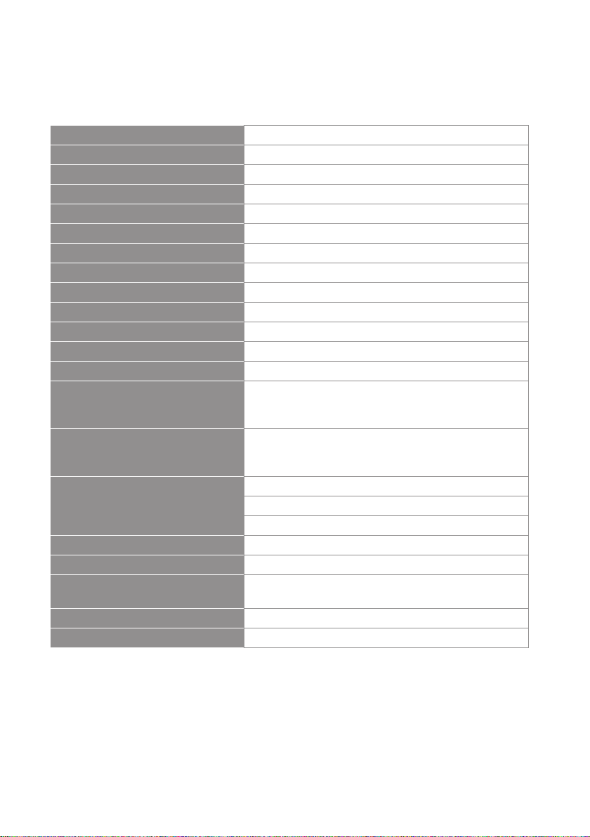
3-1 UHF PLL Dual-channel True Diversity receiver // RU-901Du
Frequency Oscillation Mode Phase-locked loop (PLL)
Carrier Frequency Range 470~960 MHz
Remoset Frequency Ultrasonic
Diversity Antenna diversity
Bandwidth 36MHz
Signal/Noise Ratio >105dB(A)
Total Harmonic Distortion (Thd) <0.6%@1KHz
Receiving Sensitivity -95dBm,S/N>80dB
Image Rejection Ratio >80 dB
Frequency Response 50Hz~16KHz±2dB
Antenna Type 1/2λ BNC detachable
Antenna Booster Power DC12~15V/100mA
Function Display By LCD
Contents Of Display
Group, channel, frequency, battery level, antenna A/
B, muting level, AF indication, RF indication, channel
scanning, output level attenuation, volume indication
Control Functions
Power, group, channel, frequency, muting level, button
lock, volume, output attenuation (XLR), scan ,Mix
Output
Audio Frequency Output Level
Ref:±22.5KHz Dev@1KHz Tone
ψ6.3 Phone Jack:-10dBV
XLR Jack:-4dBV(Line)、-24dBV(MIC)
Audio Frequency Output Impedance 600Ω
Muting Noise muting and tone code locking
Output Port 2 x balanced XLR jack
2 x unbalanced ϕ6.3 jack
Power Supply 12~15V DC / 1A
Dimension (Mm) 212.3mm (W) x 38.3mm (H) x 144mm (L)

WIRELESS MICROPHONE SYSTEM
3
3-2 UHF PLL hand-held transmitter // RU-G3TH
Frequency Oscillation Mode Phase-locked loop (PLL)
Carrier Wave Frequency Range 470~960 MHz
Remoset Frequency Ultrasonic
RF Power Output 10mW/50mW(as per local regulations)
RF Stability <±10KHz@Fc
Modulation Frequency Shift ±48KHz
Harmonic Radiation <-50dBc
Display By LCD+LED
Controls Power, mute, group, channel, frequency, sensitivity
adjustment, auto o, button lock, RF power
Battery AA alkali battery or MiNH rechargeable battery x 2
Charging Yes
Dimension 51mm (W) x 269mm (H) x 26mm (L)

4
3-3 UHF PLL body-pack transmitter // RU-G3TB
3-4 Optional condenser microphone
Lavaliere microphone // CM-501 CM-201i CM-125i
Frequency Oscillation Mode Phase-locked loop (PLL)
Carrier Wave Frequency
Range
470~960MHz
Remoset Frequency Ultrasonic
RF Power Output 10mW/50mW(as per local regulations)
RF Stability <±10KHz@Fc
Modulation Frequency Shift ±48KHz
Harmonic Radiation <-50dBc
Functions Mute, auto o, input level attenuation, sensitivity
adjustment, low power indication, RF power
Display By LCD+LED
Input Port 4 pin Mini XLR
Controls Power, mute, group, channel, frequency, sensitivity
adjustment, input level attenuation, auto o
Battery AA alkali battery or MiNH rechargeable battery x 2
Charging Yes
Dimension 62mm (W) x 80.3mm (H) x 22.6mm (L)
Model CM-501 CM-201i CM-125i
Connector 4-pin mini XLR 4-pin mini 4-pin mini XLR
Frequency Response 100~15,000 Hz XLR60~15,000 Hz 50~18,000 Hz
Polar Pattern Cardioid Omni-directivity
Sensitivity (at 1000Hz) -60 ± 3dB -60 ± 3dB -53 ± 3dB
Impedance 2.2K Ω 4.4K Ω
Max. SPL for 1% THD 130dB
Dimension (mm) Ø10.1mm (W) x
26.4mm (H)
Ø5mm (W) x
9mm (H)
Ø4mm (W) x
11mm (H)
Net Weight 21.5g 20.7g 7g (cable not included)

WIRELESS MICROPHONE SYSTEM
5
Headset microphone
Model CM-214i CM-214Ui CM-214ULi
Connector
801C4
(4P Mini XLR)
4P Mini XLR 801C3 (3P Mini XLR)
801C4 (4P Mini XLR)
801CS (3.5 stereo plug)
Option
Connector
801C3 (3P Mini XLR)
801CS (3.5 stereo
plug)
801CR
801CR
Frequency Response 60~15,000 Hz 30~18,000 Hz 100 ~ 18,000Hz
Polar Pattern Omni-directional Cardioid
Sensitivity (at 1000Hz) -60±3 dB -68±3 dB -65±3 dB
Impedance 1.8kΩ 680Ω 1.8kΩ
Max. SPL for 1% THD 130dB 120dB
Dimension(mm)
125mm(W) x
134mm(H)x
157mm(D)
205mm(W)x
134mm(H)x
157mm(D)
125mm(W)x
134mm(H)x
157mm(D)
Net Weight 32.9g 38.4g 18g (cable excluded)
Model CM-235i CX-504
Connector 801C4 (4P Mini XLR ) 4P Mini XLR
Frequency Response 50~18,000 Hz 30~18,000 Hz
Polar Pattern Omni-directional Cardioid
Sensitivity (at 1000Hz) -53 ± 3dB -68 ± 3dB
Impedance 1.8kΩ 680Ω
Max. SPL for 1% THD 130dB 130dB
Dimension(mm)
155mm(W)x
134mm(H)x
157mm(D)
285mm(W)x
55mm(H)x
111.3mm(D)
Net Weight 17g (cable excluded) 56.3g

6
Compatible Instrument Microphone // CX-500 CX-500F CX-520
CX-508W CX-516W
Ear-hook microphone // CM-801 CM-804i CM-8015 CM-825i
Model No CX-500 CX-500F CX-520
Connector 4P Mini XLR 4P Mini XLR 4P Mini XLR
Frequency Response 20~20,000 Hz 20~20,000 Hz 50~16,500 Hz
Polar Pattern Omni-directional Omni-directional Supercardioid
Sensitivity (at 1000Hz) -58±3dB -58±3dB -78±3dB
Impedance 1.5kΩ 1.5kΩ 600Ω
Max. SPL for 1% THD 130 dB 130 dB 148 dB
Good For Violin Flutes Harmonica
Model No CX-508W CX-516W
Connector 4P Mini XLR 4P Mini XLR
Frequency Response 50~18,000 Hz 30~18,000 Hz
Polar Pattern Cardioid Cardioid
Sensitivity (at 1000Hz) -67±3 dB -67±3 dB
Impedance 220Ω 220Ω
Max. SPL for 1% THD 130 dB 130 dB
Good For Winds Accordion
Model No CM-801 / CM-804i CM-8015 / CM-825i
Connector 801C4 (4P Mini XLR) 801C4 (4P Mini XLR)
Option Connector
801C3 (3P Mini XLR)
801CS (3.5 stereo plug)
801CR
801C3 (3P Mini XLR)
801CS (3.5 stereo plug)
801CR
Frequency Response 60~15,000 Hz 50~18,000 Hz
Polar Pattern Omni-directional Omni-directional
Sensitivity (at 1000Hz) -64±3 dB -53±3 dB
Impedance 1.8kΩ 1.8kΩ
Max. SPL for 1% THD 130dB 130dB

WIRELESS MICROPHONE SYSTEM
7
4. Description of parts
4-1 UHF PLL Dual-channel diversity receiver( True Diversity ) // RU-901Du
Front panel
5
6
7
8
1
4
2
3
Power ON/OFF:
ON:push once to turn on.
OFF:push and hold until ''Power OFF'' is shown on the LCD to turn o.
EXIT: Push exit to cancel a selection or exit from the current menu when RU-
901Du is in the ''setting menu.''
Rotary Switch: when in the ''function menu,'' turn the switch to select the
desired function; push the switch (or SETUP) to enter the selection and spin the
switch to select the setting. Push [SETUP] to save the setting.
SETUP: Push and hold for 2 seconds to enter the“setting menu.”Push SETUP to
save the setting once the selection and setting are made according to
''3. Rotary Switch.''
:this allows user to synchronize the transmitter after modifying a
parameter. Push “ ” to synchronize the settings to the transmitter.
Remoset indicator: this shows the current pairing status. It ashes rapidly
when data is being transmitted and the ashing stops when the synchronization
is completed. However, the ashing slows down if synchronization fails after a
period of time of pairing attempt.
Ultrasonic transmission unit: it transmits digital pairing data at ultrasonic fre-
quency. When setting, direct the ultrasonic receiving element of the microphone
to the ultrasonic transmitting unit of the receivers. The eective range is 30º on
both sides with the optimized distance at 30cm.
LCD display: See ''Receiver LCD display instructions.''
AF: indicates the current strength of audio frequency signals.
RF: indicates the current strength of radio frequency signals.
Key lock: push and hold for 2 seconds to lock all keys, and again to unlock.
Volume keys: push▲/▼keys to adjust the volume between 0 and -31dB.
Selection key: push this button
a. Push SETUP to enter the setting for the selected channel for parameter
settings.
b. Push REMOSET to transmit the setting data to the transmitter in this
selected channel.
9
10
11
12
13

8
R -901Du
EXITSETUP
2
Channel Receiver
PUSH / CONTROL
SEL. SEL.
CH1 CH2
147
5
8
9
13
23 10
12611
Rear panel
100mA
12V out
ANT. 2
100mA
12V out
ANT. 1
700
Freq.Range:
Made in Taiwan
RISK OF ELECTRIC SHOCK
DO NOT OPEN
CAUTION
2
3
5 524 41
DC power socket: for 12~15V DC / 1A power supply
XLR audio jack: balanced audio signal output
XLR audio jack: balanced audio signal output after mixing
Ø6.3 audio output jack: unbalanced audio signal output after mixing
Antenna A (B) input terminal: BNC antenna input jack that also provides
DC12V/100mA output.
1
2
3
4
5

WIRELESS MICROPHONE SYSTEM
9
2
11
10
7
3
65
4
8
3
4
6
7
2
5
1:Antenna Selection A/B. The Receiver is mute.
: Transmitter Battery Level
:Frequency (Group/Channel)
: Frequency
: Key Lock (Key Lock ON)
: Volume
: Output attenuation ON
Content Displayed under the Non-Setting Mode:
8
9
10
Setup Menu
RX1: Set the Receiver's Channel 1. RX2: Set the Receiver's Channel 2.
1: Set the Receiver's Channel 1. 2: Set the Receiver's Channel 2.

10
4-2 UHF PLL hand-held transmitter // RU-G3TH
1
4
2
5
3
6
7
8
9
10
9
6
5
1
2
7
8
3
10
4
Power: push to turn the transmitter on. When the transmitter is on, push and
hold for 2 seconds to turn it o.
Mute: while the transmitter is on, switch Mute up to talk and down to mute. If
the transmitter is o, switch the Mute up to turn the unit on. The transmitter
turns itself o automatically after 1, 10 or 30 minutes of muting depending on
setting.
Ultrasonic receiving unit: it receives pairing signals from the ultrasonic
transmission unit at the receiver end.
Battery holder: it holds UM3, AA 1.5V battery or rechargeable battery x 2.
LED indicator: it shows the transmitter’s status, including battery level, mute
and pairing indication.
LCD display: it shows the parameter settings in the transmitter.
SET: it allows parameter settings, including frequency, group, channel, sensitiv-
ity, transmission power, auto o countdown and machine code.
▲/▼: these are used with “SET” to change the parameter settings.
: push and hold the “LOCK” button for 2 seconds to lock the buttons. Push and
hold again for 2 seconds to unlock.
Charging contact: if rechargeable batteries are used, this microphone can be
recharged with an optional charger.

WIRELESS MICROPHONE SYSTEM
11
LED
Green Battery > 2V
Flashing green Microphone mute
Red Battery ≤ 2V
Alternating red and green Microphone mute (and battery low)
Blue Pairing successful
Flashing blue Data receiving error
Indicators
Battery charging is supported. The transmitter turns off automatically when
charging.
When battery is < 1.8V, the transmitter will turn off automatically.
If the microphone is turned off with the mute switch on mute, just slide the switch
up to turn the microphone on.
Others

12
4-3 UHF PLL body-pack transmitter // RU-G3TB
LCD display
Ultrasonic receiving unit: it receives the pairing signals from the
ultrasonic transmission unit at the receiver end.
REMOSET indicator: Blue:Pairing successful
Flashing blue:Date receiving error
Power:
(1)On: push the power button
O: push and hold the power button for 2 seconds till the display
shows “Power O.”
(2)Exit Setting Menu: when in the Setting Menu, push the power button
to return to the main screen.
▲/▼: these are used with “SET” to change the parameter settings.
SET: to set and save
Mute Switch / LED Indicator :
(1)Show green light when power is on.
(2)Show red light when battery level is too low.
(3)Flash red light when switch to ''MUTE'' function to mute the transmitter.
(4)Flash red light and green light when mute function is on and battery
level is too low.
Battery tray
UHF PLLTransmitter
1
2
3
4
8
5
6
7
1
4
2
5
3
6
7
8

WIRELESS MICROPHONE SYSTEM
13
Clip
4 Pin Mini XLR
3 Pin Mini XLR
3.5 Stereo Plug
4Pin Hirose connecter
Windscreen
1
3
4
5
6
2
4-5 Optional Condenser Microphone
Lavaliere Microphone // CM-501 CM-201i CM-125i
CM-501 CM-201i CM-125i
666
1
1 1
2 3 4 5
Option
Option
Option
4-4 Optional remote mute switch PT-RMS
PT-RMS

14
Gooseneck
Adjustable headband
Headband
4 Pin Mini XLR
3 Pin Mini XLR
3.5 Stereo Plug
4Pin Hirose connecter
Windscreen
Headset Microphone // CM-214i / CM-214Ui / CM-214ULi / CM-235i /
CX-504
CM-214i CM-214Ui
CM-235i
CM-214ULi
CX-504
2
4
5
6
7
8
1
3
2 2 2
8 8 8
1 1 1
2 3
8
8
1
1
Standard :
4 Pin Mini XLR
3 Pin Mini XLR
3.5 Stereo Plug
5 64 7
Option
Option
Option

WIRELESS MICROPHONE SYSTEM
15
Ear-hook Microphone // CM-801 / CM-804i / CM-8015 / CM-825i
Boom
Adjustable Headband
Adjustable ear hook
Detchable Cable
Cable Clip
Windscreen
4 Pin Mini XLR
3 Pin Mini XLR
3.5 Stereo Plug
4Pin Hirose connecter
6
8
7
9
10
3
5
4
1
2
2
6
3
5
4
1
63
5
4
1
2
6
3
5
4
1
63
5
4
1
CM-801
CM-804i
CM-8015
CM-825i
8 97 10
Option
Option
Option

16
Compatible Instrument Microphone // CX-500 / CX-500F / CX-520 /
CX-508W / CX-516W
Gooseneck
Clip
Bracket
Volume Control
Windscreen
4 Pin Mini XLR
1
2
3
4
CX-508W CX-516W
1 1
2
5
6
6
3
5
5
5
5CX-500F
CX-500
1
2
CX-520
4
Other manuals for RU-901Du
1
This manual suits for next models
2
Table of contents
Other JTS Microphone System manuals