Enconnex AC6000 User manual

Enconnex AC6000 UPS
USER MANUAL

Legal Disclaimer
This document is meant for instructional purposes only. This publication is not meant to
be a substitute for a detailed operational and site-specific development plan. Therefore,
Enconnex assumes no liability for damages, violations of codes, improper installation,
system failures, or any other problems that could arise based on the use of this
publication.
This publication has been compiled in good faith by Enconnex. However, no
representation is made, or warranty given, either expressed or implied, as to the
completeness or accuracy of the information this publication contains.
Enconnex reserves the right to make changes or updates with respect to or in the content
of the publication or the format thereof at any time without notice. Copyright, intellectual,
and all other proprietary rights in the content (including but not limited to software, audio,
video, text, and photographs) rests with Enconnex or its licensors. All rights in the content
not expressly granted herein are reserved. No rights of any kind are licensed or assigned
or shall otherwise pass to persons accessing this information.
This publication shall not be for resale in whole or in part

Table of Contents
Legal Disclaimer 1
Table of Contents 2
Figures 4
Tables 5
AC6000 Safety Information 6
Handling and Electrical Safety Information 6
Disclaimers 7
Life Support Applications 7
Product Introduction 9
Overview 9
AC6000 Features 10
Advanced Battery Management System 10
Automated Software Interface 10
User Interface - Front Panel with Bezel 11
Connectors and Controls - Rear Panel 12
Enconnex AC6000 Technical Specifications 13
AC6000 Installation Procedure 16
About this Procedure 17
AC6000 Mount Example 16
Materials Needed 17
Box Contents 17
Slide Rail Assembly (optional) 17
Instal the Inner Slide Rails on the AC6000 17
Installing the Outer Slide Rails 19
Field Wiring 19
Power-up and Shutdown Procedure 21
About This Procedure 21
Powering Up the AC6000 21
Visual Verification 29
Modes of operation 23
5.4.1 Standby Mode 23
5.4.2 NormalUPS Mode 23
Communicating with the AC6000 29
Webpage (HTTP) Configuration 24
SNMP Configuration 29

AC6000 Display 30
LCD Display Icons 30
Default Screen 30
Navigation 31
Main Menu 31
Reset to Factory Default Settings 35
Faults and Alerts 35
AC6000 Website 38
Home Page 38
Network Configuration 38
UPS Configuration 38
Control 38
System Status 38
DB9 and REPO Port Pin-Outs 39
REPO Connector 39
Serial Communication 39
Troubleshooting 40
Appendix 45
Safety Symbols and Definitions 45

Figures
Figure 2.1-1: AC6000 Drawing
Figure 2.1-2: AC6000 System Overview
Figure 2.5-1: AC6000 Front Panel Callouts
Figure 2.6-1: AC6000 Rear Panel
Figure 4.1-1: AC6000 Example Installation
Figure 4.4-1: Enconnex Adjustable Mounting Rails
Figure 4.4-2: Enconnex Adjustable Mounting Rails
Figure 4.4-3: Slide Rail Mounting.
Figure 4.4-4: AC600 Enclosure with optional Enconnex slide rails attached.
Figure 4.5-1: Hard-wiring inspection and assembly.
Figure 5.2-1: AC6000 Rear Panel
Figure 5.2-2: AC6000 Power Button Location
Figure 5.5-1: AC6000 Rear-Panel Communication Ports for Troubleshooting
Figure 6.3-1: AC6000 User Input Controls
Figure 6.4-1: AC6000 Front Panel Menu
Figure 8-1: Expansion Communication Ports and REPO Connector
Figure 8.1-1: REPO Connector Pin-Out
Figure 8.2-1: Serial and Ethernet Pin-Outs

Tables
Table 2.5-1: User Interface and Controls
Table 2.6-1: AC6000 Rear Panel Detail
Table 3-1: AC6000 Technical Specifications
Table 4.2-1: Materials Needed
Table 4.5-1: Field Wiring Table
Table 5.3-1: Icons and Descriptions
Table 5.5-1: Webpage Default Username and Password.
Table 5.5-2: Parameter Table
Table 6.4-1: Front Panel Menu
Table 6.6-1: AC6000 Beep Codes
Table 6.6-2: Beep Control Mode
Table 6.6-3: Fault Messages and Descriptions
Table 6.6-4: Display Messages and Descriptions
Table 9-1: Troubleshooting: Problems and Solutions
Table 9-2: Error Codes, Messages and Descriptions
1. AC6000 Safety Information
1.1. Handling and Electrical Safety Information
IMPORTANT SAFETY INSTRUCTIONS — SAVE THESE INSTRUCTIONS
This document contains important information and direction that should be followed
during installation, maintenance, and usage of this product. Before installing or operating
this equipment, please read all instructions, warnings and cautions. Save this manual for
future reference.
- DANGER
This UPS contains LETHAL VOLTAGES. All repairs and service should be performed only
by an Enconnex-AUTHORIZED SERVICE PERSONNEL.
Fuses are permanently installed. There are NO SERVICEABLE PARTS inside this product.
- WARNING
● Personnel should be knowledgeable of the processes before attempting to install,
configure or replace this equipment.
● It is important to note that this UPS contains its own energy source (lithium-ion cells).
Its output may produce high voltages and currents even when it is not connected to
AC mains.
● This system contains live batteries that may present a shock hazard even when
disconnected. Output safeguards such as disconnect switches, interlocks, etc. must
be provided by user.
● Connect only to a mains provided with branch circuit overcurrent protection. This
must be performed in accordance with the National Electrical Code® (NEC)
ANSI/NFPA 70 and applicable codes of local jurisdictions.
● Leakage current of this UPS and all connected equipment must not have an earth
leakage current greater than 3.5 milliamperes per international standards and wiring
regulations.
● For 230V/50Hz models, cables should not exceed ten meters in length.
● Lithium ion is a Class 9 hazardous material and must be shipped in accordance with
CFR 49. Please contact your Enconnex representative when shipping a unit for return
or other purposes.
● Contact Enconnex agent for service, recycling, and disposal instructions. Also visit
earth911.com for instructions on disposal.
● Damage will occur if the input or output AC terminals are shorted. Enconnex is not
responsible for damages to the UPS incurred in this manner.

- CAUTION
● Install this UPS in a clean, temperature- and humidity-controlled indoor location in
order to reduce the risk of fire or electric shock. Ambient temperature must not be
above 40°C (104°F) or below 0°C (32°F). Do not locate near water or excessive
humidity (95% maximum).
● It is advisable to not bring superfluous conductors into the installation area. Before
beginning maintenance or installation, please remove jewelry (e.g. watches, rings and
necklaces). Metal conductors have the potential to short between power terminals
(power and ground, commonly) and nearly instantly heat to very high temperatures
when connected between them. This can cause serious burns and/or weld a metal
object to the terminals.
● This system is cooled through forced air convection. Do not block air flow of fans and
allow adequate space on the front and rear of the unit for proper ventilation.
● This equipment has been tested and found to comply with the limits for a Class-A
digital device, pursuant to Part 15 of the FCC Rules. These limits are designed to
provide reasonable protection against harmful interference when the equipment is
operated in a commercial environment. This equipment generates, uses and can
radiate radio frequency energy and, if not installed and used in accordance with the
instruction manual, may cause harmful interference to radio communications.
Operation of this equipment in a residential area is likely to cause harmful interference
that the user must correct, including the expense of all corrective modifications.
● This system is suitable for IT (impedance-grounded) systems.
1.2 Disclaimers
Modification or changes to the AC6000 not performed or expressly approved by
Enconnex may void the unit's warranty.
The integral battery is not field-replaceable. There are no user-replaceable fuses within.
Contact Enconnex Customer Support for assistance.
The AC6000 is designed for installation in temperature-controlled, indoor areas free of
conductive contaminants. See Technical Specifications for more information.
1.3 Life Support Applications
The Enconnex AC6000 is not for use in life support applications where failure or
malfunctions of the unit can be reasonably expected to cause failure of the life support

device or to significantly affect its safety or effectiveness. The Enconnex AC6000 is not
for direct patient care.
Enconnex will not knowingly sell its products for use in such applications unless it
receives in writing assurances satisfactory to Enconnex.
The AC6000 does not meet medical standard requirements for use in direct patient care.
2. Product Introduction
2.1 Overview
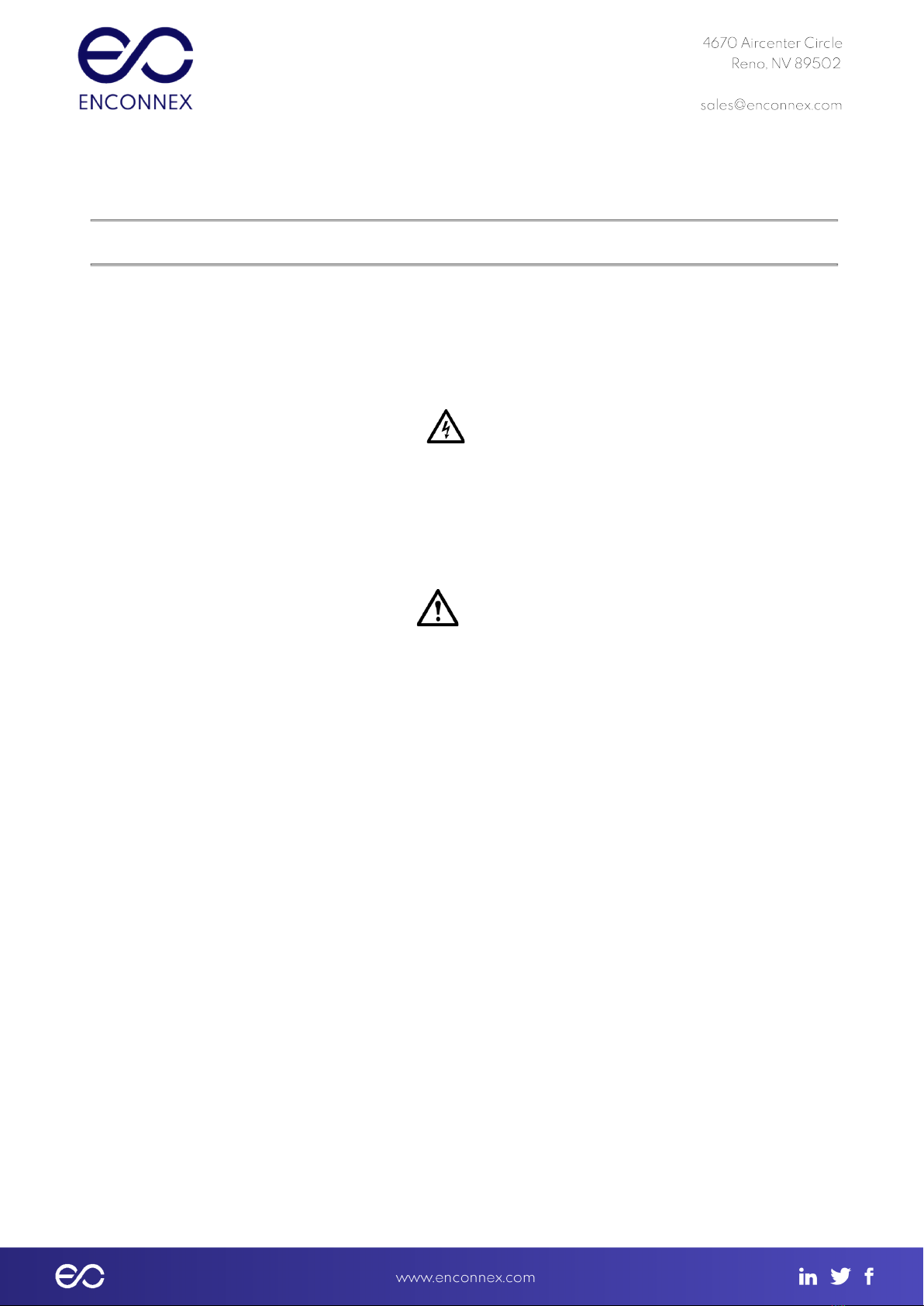
The Enconnex AC6000 is a highly integrated line-interactive uninterruptible power
system (UPS). Integrating the electronics and a battery capable of supplying 6kWs of
power for 6 minutes contained within a small 2RU form factor, this system is designed
to protect servers in the back office and data center environments.
Figure 2.1-1: AC6000 Drawing
The line-interactive approach captures the best features of UPS topologies: Its
electronics are mostly inactive, but always “armed”. They’re at the ready for the next
power interruption. Switchover to UPS Mode occurs within ¼to ½cycle of the 60 Hz
mains.
This translates to full power available with an interruption of 4 to 8 thousandths of a
second. Most, if not all, IT equipment is designed to never notice this very high-speed
handoff.
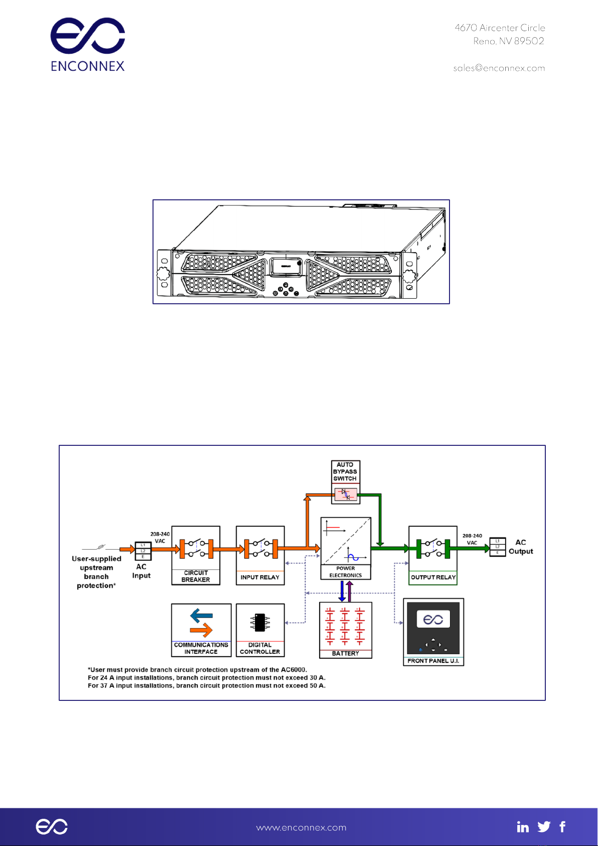
Figure 2.1-2: AC6000 System Overview
The AC6000 is versatile and extensible. It can serve to supplement mains power
during peak energy consumption times using unique peak shaving technology. This

highly efficient unit operates with an input and output of 208, 230, or 240 VAC. It is
capable of supporting equipment drawing up to 6kW. This power-dense 2RU unit
contains highly efficient power electronics and a safe, high-performance lithium-ion
battery pack.
2.2 AC6000 Features
● Supplies up to 6000 watts of power for 6 minutes.
● Uses compact, safe lithium-ion technology for energy storage.
● Rapid recharge.
● Peak shaving capability to supplement power supply during high demand.
2.3 Advanced Battery Management System
● Leverages years of automotive research.
● Maintains battery cell power balance.
● Highly efficient power management with low quiescent draw.
● Integrated safety electronics.
● Provides active thermal management of cells.
2.4 Automated Software Interface
● Supports serial or SNMP communication
● Reports critical performance metrics
● Allows for firmware updates of internal microprocessors
● Provides for network communication configuration.
Alerts are generated for indicating low remaining power, announcing operational modes and
notification of performance-related issues.

2.5 User Interface - Front Panel with Bezel
Figure 2.5-1: AC6000 Front Panel Callouts
No.
Item
Type
Name
Description
1
Knob
Fastener
Knob Screw
Screw with molded knob/thumb screw.
2
Display
LCD
User
Interface
Screen
LCD screen which shows status, battery,
power, and alert/fault conditions and allows
unit configuration.
3
Button
Momentary
Power
Used to change the operating state of the
unit.
4
Button
Momentary
Left
Navigation button to move selection on
display left.
5
Button
Momentary
Up
Navigation button to move selection on
display up.
6
Button
Momentary
Down
Navigation button to move selection on
display down.
7
Button
Momentary
Right
Navigation button to move selection on
display right.
8
Button
Momentary
Menu
Navigation button to display the Main Menu.
Table 2.5-1: User Interface and Controls

2.6 Connectors and Controls - Rear Panel
Figure 2.6-1: AC6000 Rear Panel
The AC6000 comes equipped with forced air convection cooling multiple standard
configurations, and is Ethernet or serial compatible.
No.
Item
Type
Name
Description
1
Fan
Ventilation
Cooling Fan
Extracts air from the AC6000 enclosure.
Speed controlled by internal temperature
regulation. Air flows from the enclosure
bezel cold side.
2
Connectors
DB9
RS485.CAN
DB-9 female connector reserved for future
use.
3
Connector
Phoenix
REPO
(Remote
Power-Off)
Depending on user preference, the REPO
feature can be configured in three ways::
1. not used
2. normally open (top two positions)
3. normally closed (bottom two positions)
The default configuration is normally closed.
4
Switch
Circuit
Breakers
Power
Switch
Provides Input over-current protection as
well as a means to disconnect the input
power from the AC6000
5
Connector
RJ45
RS232
Serial
RS232 console for configuration and
monitoring.
6
Rail/Mountin
g Brackets
Slide
Rail/Mounting
Brackets
Left & Right
Slide Rails
and
Attaches device to slide rails a allows the
AC6000 to be extracted from the
enclosure for service.

Mounting
Brackets
7
Connector
RJ45
Ethernet
port
Ethernet port provides network connectivity.
8
Cable
Management
Compression
Clamps
Input /
Output
Secures the power cable connections for
power I/O.
Table 2.6-1: AC6000 Rear Panel Detail
3. Enconnex AC6000 Technical Specifications
System Specifications
Efficiency
93%
Power Protection
Mechanical Circuit Breaker (MCB), electronic monitoring and
control, fusing, fuse links
System Power Factor
>0.9
Battery Protection
Discharge, Overcharge, Overcurrent, Thermal
6000 W, max.
6 minutes
Environmental
Operating Temperature
Range
0°C to +40°C
Storage Temperature Range
-20°C to +60°C
Humidity
0% to 95%, Non-Condensing

Cooling Method
Integrated Forced Air
Physical Specifications
Case Material
Steel
Dimensions, Inches
2U: 3.5 H x 19.0 W x 32.0 D
Weight
approx. 90 lbs.
Battery Capacity
1000 Watt-Hours

Electrical Power Connectors
Standard:
Input: NEMA L6-30R (24A input)
Output: NEMA L6-30P
Optional:
For 6kW output on 50A service:
Option 1 – CS8265/4
Option 2 – Hardwire I/O
(Intended for loads in excess of 5kW to
accommodate full power at low line conditions.)
Option 3 – For Europe, 24A input using 332C6/P6.
Note: User must include upstream branch protection. For
standard configuration and option 3, branch protection must
not exceed 30 A. For Options 1 & 2, branch protection must
not exceed 50 A.
Table 3-1: AC6000 Technical Specifications
4. AC6000 Installation Procedure
4.1. About this Procedure
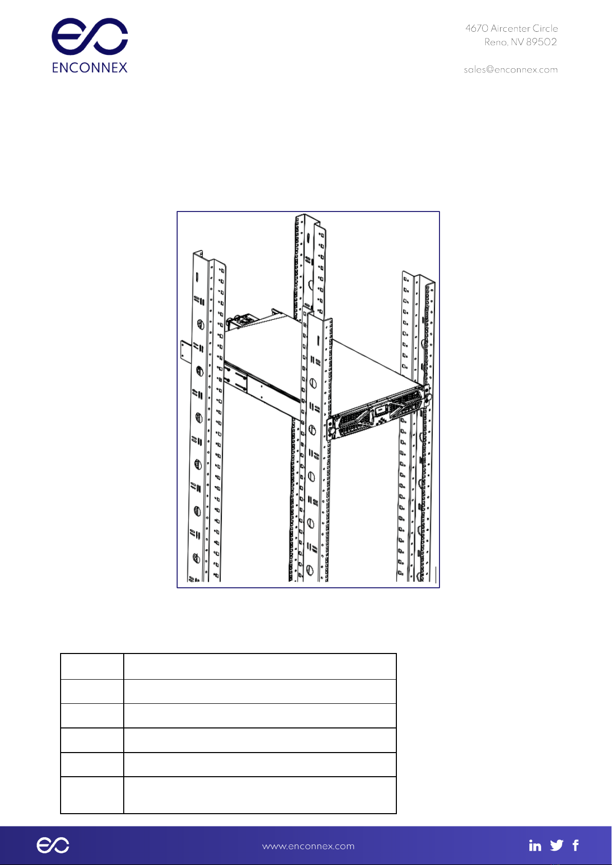
This procedure covers the installation of the AC6000 UPS unit into a standard 19-inch
rack enclosure.
4.1.1 AC6000 Mount Example
Figure 4.1-1: AC6000 Example Installation
4.2. Materials Needed
Qty.
Material
1
Set of AC6000 UPS and Hardware
2
Slide Rails
8
M3x8 Phillips Head Screws (Not supplied)
12
#12-24 Cage Nuts (Supplied with Rails)
12
#12-24 x ⅝” Pilot Point Machine Screw (Supplied with
Rails)

4
#12-24 x 1” Machine Screw
Table 4.2-1: Materials Needed
4.3. Box Contents
The AC6000 container should have the following items:
● User Manual
● AC6000 with input and output power cables
● Mounting rails with hardware (optional)
Table 4.3-1: Box Contents
4.4 Slide Rail Assembly (optional)
Figures 4.4-1 & 4.4-2: Enconnex Adjustable Mounting Rails.
Slide rail assemblies are recommended for mounting the AC6000 UPS.
4.4.1 Install the Inner Slide Rails on the AC6000
Materials Needed:
● M3x8 Phillips Head Screws (qty. 8)
● Inner Slide Rails (qty. 1 set)
Figure: 4.4-3: Inner Slide Rails
Tools Required:
● Phillips Head Screwdriver
● Cage Nut Compressor Tool
The optional inner slide rails attach to the left and right sides of the AC6000 enclosure (The rails
are marked with “Left” and “Right” for reference. They are fastened to the enclosure with
screws into the supplied PEM nuts. The illustration below shows the interior of the AC6000.
PEM rivet nut locations circled in red.
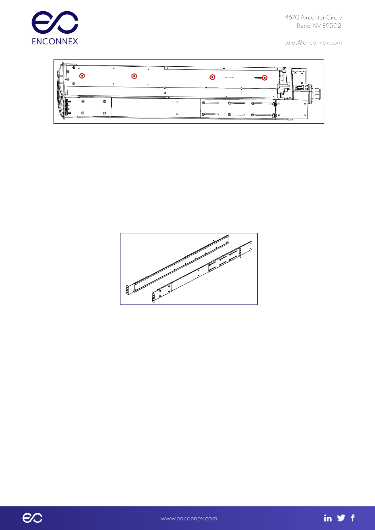
Figure 4.4-4: Slide Rail Mounting.
Step 1: Remove the slide rail assembly from it’s packing materials.
Step 2: Remove the inner rails and extract them from the outer rail channels
Step 3: Fasten the inner rails to the AC6000 enclosure.
4.4.2 Installing the Outer Slide Rails
Materials Needed:
● #12-24 x ⅝” Pilot Point Machine Screw (qty. 8)
● Cage Nuts (qty. 12)
● Outer Slide Rails (qty. 1 set)
Figure 4.4-5: Outer slide rails
Tools Required:
● Phillips Head Screwdriver
● Cage Nut Compressor Tool
Step 1: Select installation height on the rack posts where you will mount left and right
outer slide rails.
Step 2: Install 4 cage nuts in each front rail, and 2 cage nuts in each back rail as shown in the
picture.

Front Rail Rear Rail
Step 3: Adjust the rear slider plate on the Outer Sliding rails to increase or decrease the length
of the rails to properly fit the cabinet.
Step 4: Attach the Outer Sliding Rails (stationary) to the cabinet front mounting rails using 2
screws on each side of the rail. These screws will be placed in the middle two holes. The outer
two holes will be where the AC6000 is mounted.
NOTE: Do not tighten completely as they may need to be adjusted for the width of the AC6000
● AC6000 screw
● Outer Slide Rails screw
● Outer Slide Rails screw
● AC6000 screw
*Above is the order for which the screws will be installed.
Step 5: With the rails at the proper length, install 2 cage nuts and 2 screws at the rear of the
cabinet to fasten the stationary rail to the cabinet. Place the screws at the top and bottom of
the 4 holes.
Step 6: With two people, lift the AC6000 unit into the cabinet by inserting the sliding rails on the
UPS (AC6000) into the track of the stationary Outer Slide rails. Approximately ⅓of the way in
you will hear a click. This is the latch engaging which disables the rail from being completely
pulled out. When fully seated install the remaining 4 screws into the cage nuts to secure the
unit in the rack.
To remove the AC6000 remove the mounting screws on each side, and slide the unit out. When
the latches are exposed activate them while continuing to slide the unit out of the
4.5 Field Wiring
● To wire the unit in the field, ensure that the electrical service is properly rated for
the desired output.
Table of contents
Popular UPS manuals by other brands

Tripp Lite
Tripp Lite INTERNET OFFICE 300 Manual Del Usuario

Tripp Lite
Tripp Lite Power Suppy owner's manual

Tripp Lite
Tripp Lite SmartOnline owner's manual

Tripp Lite
Tripp Lite DCOW 2 owner's manual

Tripp Lite
Tripp Lite SmartOnline SU40K owner's manual

Contec
Contec CONPROSYS Alpha Series Reference manual

Tripp Lite
Tripp Lite SmartPro SMART3000RMXL2U owner's manual

MetaSystem
MetaSystem MEGALINE 1250 RACK instruction manual

Tripp Lite
Tripp Lite SmartOnline AGPS5548 owner's manual

Tripp Lite
Tripp Lite BCPRO850 Features and specifications

Tripp Lite
Tripp Lite SmartPro SMART1500RM2U Specification sheet

Tripp Lite
Tripp Lite SmartOnline 3-Phase 10kVA owner's manual


