Endress+Hauser Ecograph T RSG30 User manual

BA194R/09/en/13.10
No.: 51009564
Software
ETU00xA, V2.02.xx
Operating Instructions
Multi Channel Recorder RSG30
Ecograph T

2
Brief overview
For quick and easy commissioning:
Brief Operating Instructions
Your new unit has the Operating Instructions built-in. The unit's simple control system enables you
to commission for many applications, practically without any paper. Your unit displays instructions
at the push of a button directly on screen. This description is nevertheless delivered with the unit -
it is a supplement to the Operating Instructions built into the unit. Anything that is not described
directly at the unit by plain text or menus is explained here.
Fig. 1: Variable softkey (e.g. calling up internal Help function in the Setup menu)
Index
A very extensive index can be found at the end of these Operating Instructions. It acts as a
complement to the table of contents and helps you find special terms and functions.
1. Consider the safety instructions Page 5
2. Install the unit Page 8
3. Wire up the unit Page 11
4. Install the provided PC software Page 22
5. Connect the unit with the PC Page 22
6. Set up the unit (via provided PC software) Page 27
7. Transmit the set up files to the unit Page 27
E

3

Table of contents
4
Table of contents
1 Safety instructions . . . . . . . . . . . . . . . . 5
1.1 Designated use . . . . . . . . . . . . . . . . . . . . . . . . . . . . 5
1.2 Installation, commissioning and operation . . . . . . . . 5
1.3 Operational safety . . . . . . . . . . . . . . . . . . . . . . . . . . 5
1.4 Return . . . . . . . . . . . . . . . . . . . . . . . . . . . . . . . . . . 5
1.5 Notes on safety conventions and icons . . . . . . . . . . 6
2 Identification . . . . . . . . . . . . . . . . . . . . 7
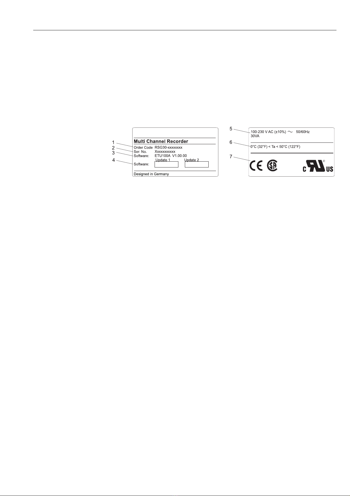
2.1 Device designation . . . . . . . . . . . . . . . . . . . . . . . . . 7
2.2 Scope of delivery . . . . . . . . . . . . . . . . . . . . . . . . . . 7
2.3 Certificates and approvals . . . . . . . . . . . . . . . . . . . . 7
3 Installation . . . . . . . . . . . . . . . . . . . . . . 8
3.1 Incoming acceptance, transport, storage . . . . . . . . . 8
3.2 Installation conditions . . . . . . . . . . . . . . . . . . . . . . . 8
3.3 Installation instructions . . . . . . . . . . . . . . . . . . . . . . 8
3.4 Mechanical locking . . . . . . . . . . . . . . . . . . . . . . . . 10
3.5 Post-installation check . . . . . . . . . . . . . . . . . . . . . 10
4 Wiring. . . . . . . . . . . . . . . . . . . . . . . . . 11
4.1 Quick wiring guide . . . . . . . . . . . . . . . . . . . . . . . . 11
4.2 Terminal assignment . . . . . . . . . . . . . . . . . . . . . . 14
4.3 Degree of protection . . . . . . . . . . . . . . . . . . . . . . . 18
4.4 Post-connection check . . . . . . . . . . . . . . . . . . . . . 18
5 Operation . . . . . . . . . . . . . . . . . . . . . . 19
5.1 Quick operating guide . . . . . . . . . . . . . . . . . . . . . 19
5.2 Display and operating elements . . . . . . . . . . . . . . . 20
5.3 Entering text and numbers . . . . . . . . . . . . . . . . . . 21
5.4 Overview of the symbols used . . . . . . . . . . . . . . . 21
5.5 Confirming error messages . . . . . . . . . . . . . . . . . . 22
5.6 Communication; PC software installation . . . . . . . 22
6 Commissioning. . . . . . . . . . . . . . . . . . 26
6.1 Function check . . . . . . . . . . . . . . . . . . . . . . . . . . . 26
6.2 Switching on the unit . . . . . . . . . . . . . . . . . . . . . . 26
6.3 Unit Set up . . . . . . . . . . . . . . . . . . . . . . . . . . . . . . 26
6.4 The set up window (at main menu) . . . . . . . . . . . 30
6.5 The main menu . . . . . . . . . . . . . . . . . . . . . . . . . . 54
6.6 Saving measured values . . . . . . . . . . . . . . . . . . . . 61
6.7 Important functions of the provided PC software . 62
7 Maintenance. . . . . . . . . . . . . . . . . . . . 64
7.1 Software update via the provided PC software . . . . 64
7.2 Instruction for releasing a software option e.g.
"Integration + Analysis + Maths" . . . . . . . . . . . . . 64
8 Accessories. . . . . . . . . . . . . . . . . . . . . 65
8.1 Accessory parts . . . . . . . . . . . . . . . . . . . . . . . . . . . 65
9 Troubleshooting. . . . . . . . . . . . . . . . . . 66
9.1 Diagnostic/unit information . . . . . . . . . . . . . . . . . 66
9.2 Troubleshooting instructions . . . . . . . . . . . . . . . . . 67
9.3 System error messages . . . . . . . . . . . . . . . . . . . . . 68
9.4 Spare parts . . . . . . . . . . . . . . . . . . . . . . . . . . . . . . 68
9.5 Return . . . . . . . . . . . . . . . . . . . . . . . . . . . . . . . . . 70
9.6 Disposal . . . . . . . . . . . . . . . . . . . . . . . . . . . . . . . . 70
9.7 Software history . . . . . . . . . . . . . . . . . . . . . . . . . . 71
10 Technical data . . . . . . . . . . . . . . . . . . . 72
10.1 Input . . . . . . . . . . . . . . . . . . . . . . . . . . . . . . . . . . 72
10.2 Output . . . . . . . . . . . . . . . . . . . . . . . . . . . . . . . . . 74
10.3 Power supply/terminal diagram . . . . . . . . . . . . . . 75
10.4 Performance characteristics . . . . . . . . . . . . . . . . . . 76
10.5 Installation conditions . . . . . . . . . . . . . . . . . . . . . . 76
10.6 Environment . . . . . . . . . . . . . . . . . . . . . . . . . . . . 76
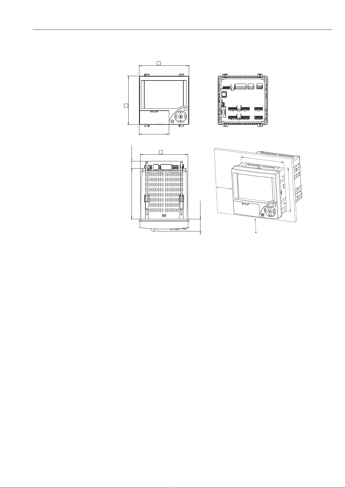
10.7 Mechanical construction . . . . . . . . . . . . . . . . . . . . 78
10.8 Human interface . . . . . . . . . . . . . . . . . . . . . . . . . . 78
10.9 Certificates and approvals . . . . . . . . . . . . . . . . . . . 81
10.10 Accessories . . . . . . . . . . . . . . . . . . . . . . . . . . . . . . 81
10.11 Documentation . . . . . . . . . . . . . . . . . . . . . . . . . . . 81
Index . . . . . . . . . . . . . . . . . . . . . . . . . . . . . . 82

Safety instructions
5
1 Safety instructions
1.1 Designated use
This unit is designed for the electronic acquisition, display, recording, analysis, remote transmission
and archiving of analog and digital input signals in non-hazardous areas.
• The unit is designed for installation in a panel or a cabinet and may only be operated in an installed
state.
• The manufacturer does not accept liability for damage caused by improper or non-designated use.
The unit can cause danger if used improperly or other than intended.
1.2 Installation, commissioning and operation
• The unit may only be installed, connected, commissioned and serviced by qualified and
authorized expert staff (e.g. electrical technicians) strictly adhering to the instructions contained
in this manual, the applicable norms, legal regulations and certificates (depending on the
application).
• These experts must have read and understood this manual and follow the instructions it contains.
• The unit may only be modified or repaired if expressly permitted in the Operating Instructions.
• Damaged units which could pose a source of danger may not be put into operation and must be
marked as defective.
• Primarily observe local regulations regarding opening and repairing electrical units.
1.3 Operational safety
• The unit is safely built and tested according to state-of-the-art technology and has left the factory
in perfect condition as regards technical safety. The applicable regulations and European standards
have been taken into account.
• Please observe the technical data on the nameplate! The nameplate is on the left-hand side of the
housing.
Desk top version
#Warning!
• The mains plug must only be inserted into a socket with grounding contact.
• The protective effect must not be removed by an extension lead without ground wire.
• Relay outputs: U(max) = 30 V eff (AC) / 60 V (DC)
Repairs
Repairs that are not described in these Operating Instructions must only be carried out directly by
the manufacturer or by the service department.
Electromagnetic compatibility
The measuring system meets the general safety requirements of IEC 61010 and the EMC
requirements of IEC 61326.
Technical improvement
The manufacturer reserves the right to adapt technical data to the most up-to-date technical
developments without any special announcement. Ask your supplier for information about activities
and possible extensions to these Operating Instructions.
1.4 Return
The following measures must be taken before you return a measuring unit, e.g. for repair or
calibration:
• The unit must be packed in protective packaging. The original packaging offers the best
protection.

Safety instructions
6
1.5 Notes on safety conventions and icons
Always refer to the safety instructions in these Operating Instructions labeled with the following
symbols:
#Warning!
This symbol draws attention to activities or procedures that can lead to injuries to persons, safety
risks or the destruction of the unit if not carried out properly.
"Caution!
This symbol draws attention to activities or procedures that can lead to defective operation or to
destruction of the unit if not carried out properly.
!Note!
This symbol draws attention to activities or procedures that have an indirect effect on operation, or
can trigger an unforeseen unit reaction if not carried out properly.
ESD - Electrostatic discharge
Protect the terminals against electrostatic discharge. Failure to comply with this instruction can
result in the destruction of parts of the electronics.

Identification
7
2 Identification
2.1 Device designation
2.1.1 Nameplate
Compare the nameplate on the left-hand side of the unit with the delivery note and with the
following diagram:
Fig. 2: 1. Order code
2. Serial number
3. Software version
4. Fields for indicating the installed software updates
5. Supply voltage, power frequency, power consumption
6. Ambient temperature range
7. Unit approvals
2.2 Scope of delivery
• Unit (with terminals, as per your order)
• 4 fastening clips
• USB cable
• Optional CompactFlash CF card (CF card is enclosed separately.)
• PC operating and configuration software on CD-ROM
• Delivery note
• Multilanguage Brief Operating Instructions as hard copy
• Operating Instructions on CD-ROM
• locking plate
Anything missing? Then please inform your supplier.
2.3 Certificates and approvals
An overview of all certificates and approvals can be found in the Technical Data, Section 10.

Installation
8
3 Installation
3.1 Incoming acceptance, transport, storage
3.1.1 Incoming acceptance
After receiving the goods, check the following points:
• Is the packaging or the contents damaged?
• Is the delivery complete? Compare the goods delivered with what you ordered.
3.1.2 Transport and storage
Observe the following points:
• The unit must be packed in shockproof packaging for storage (and transport). The original
packaging offers the best protection for this.
• The permitted storage temperature is -20 to +60 °C (-4 to 140 °F)
3.2 Installation conditions
Working temperature range:
0 to 50 °C (32 to 122 °F), max. 75% rel. humidity without condensation.
"Caution!
• To avoid heat accumulation, please always ensure that the unit is sufficiently cooled.
• Maintain distance from strong magnetic fields (see Section 10 "Technical data", interference
immunity )
• Environment at front in accordance with unit ingress protection IP 54
3.3 Installation instructions
3.3.1 Mounting tool
To install the control panel, all you need is a screwdriver.

Installation
9
3.3.2 Panel mounting, installation dimensions
Fig. 3: Panel mounting and installation dimensions
• Installation depth: approx. 171 mm (6.73 inch) (incl. terminals and fastening clips)
• Panel cutout: 138+1 x 138+1 mm (5.43+0.04 x 5.43+0.04 inch)
• Panel thickness: 2 to 40 mm (0.08 to 1.57 inch)
• Maximum point of view range: From the display center 50° to the left and right, 20° upward, 30°
downward.
• Securing to DIN 43 834
1. Push the unit through the panel cutout from the front. To avoid heat accumulation, we
recommend keeping a distance of > 15 mm (> 0.59 in) from the walls and other units.
2. Hold the unit level and then hang jack screws in the openings (2 x top, 2 x bottom).
3. Tighten the screws on the jack screws equally with a screwdriver, such that a secure seal to
the control panel is guaranteed.
!Note!
A distance of min. 15 mm (0.59 in) between the units has to be observed if aligning the units in the
Y-direction (vertically above one another).
The units can be arranged horizontally beside one another in the X direction without any spacing
between the units.
Y
X
137.9 mm
5.43”
21 mm
0.83”
150 mm
5.9”
36.1 mm
1.42”
138 mm
5.43 “
+1
+0.04
138 mm
5.43 “
+1
+0.04
86.5 mm
3.4”
144 mm
5.67”
144 mm
5.67”

Installation
10
3.4 Mechanical locking
The CompactFlash card can be secured against unauthorized removal using the locking plate
supplied. For this purpose, insert the locking plate into the slit below the handle of the cover plate
(see Fig. 4). Now you can lead-seal or seal the cover plate with a suitable lock.
Fig. 4: Inserting the locking plate
3.5 Post-installation check
After installing the control panel, please check the following points:
• Is the unit fixed firmly in the center of the control panel cutout?
• Does the seal run all around the housing collar?

Wiring
11
4 Wiring
4.1 Quick wiring guide
#Warning!
Please note that the entire electrical connection may only take place when the unit is de-energized.
"Caution!
• The ground connection must be made before all other connections. Any interruption in the
ground can cause danger.
• Before commissioning, compare the supply voltage with the information specified on the
nameplate (left-hand side of the housing).
• The mixed connection of safety extra-low voltage and dangerous contact voltage to the relay is
not permitted.
• Provide a suitable switch or circuit breaker when installing in a building. This switch must be
installed near to the unit (easily accessible) and be labeled as a separator.
• An overcurrent protective unit (nominal current 10 A) is required for the power cable.
!Note!
Please also refer to the terminal diagram on the rear of the unit.
4.1.1 Channel color table
When wiring the analog channels, please ensure that the color display on the display for the
individual channels is specified as follows:
3-channel version
Analog 1: Blue Analog 2: Red
Analog 3: Green Digital 1: Cyan
Digital 2: Red Digital 3: Green
6-channel version
Analog 1: Magenta Analog 2: Red
Analog 3: Black Analog 4: Green
Analog 5: Blue Analog 6: Brown
Digital 1: Cyan Digital 3: Red
Digital 2: Green

Wiring
12
4.1.2 Wiring diagram
Fig. 5: Circuit diagram

Wiring
13
4.1.3 Auxiliary voltage output for 2-wire sensors
Fig. 6: Using the auxiliary voltage output as power supply for 2-wire sensors (at current measurement range)
5
6
9
1
DI3
93
92
91
GND
RxD/TxD +
RxD/TxD -
Ethernet
RS232
Rel2
41
42
31
32
21
22
11
13
12
L+
N-
PE
Rel4 Rel3
Rel1
RS485
CH 4 CH 5 CH 6
611
612
613
614
615
616
411
412
413
414
415
416
CH 1 CH 2 CH 3
111
112
113
114
115
116
211
212
213
214
215
216
311
312
313
314
315
316
511
512
513
514
515
516
_
+
-
Y
+
-
Y
+
+
_
Out: max. 250 mA
On connecting channels 1-4 see
terminal connections CH 5-6
Sensor 1
e.g. TR10 from E+H
Sensor 2
External display
(optional) e.g.
RIA261 from E+H

Wiring
14
4.1.4 Auxiliary voltage output for 4-wire sensors
Fig. 7: Using the auxiliary voltage output as power supply for 4-wire sensors (at current measurement range)
4.2 Terminal assignment
"Caution!
If high-energy transients occur when using long signal cables, we recommend connecting a suitable
overvoltage protection (e.g. E+H HAW560/562).
Use shielded signal lines for serial interfaces!
4.2.1 Cable specification, spring terminals
All connections on the rear of the unit are designed as screw or spring terminal blocks with reverse
polarity protection. This makes the connection very quick and easy. The spring terminals are
unlocked with a slotted screwdriver (size 0).
Please note the following when connecting:
• Digital I/O wire cross-section, RS485 and analog inputs: max. 1.5 mm2(14 AWG) (spring
terminals)
• Power wire cross-section: max. 2.5 mm2(13 AWG) (screw terminals)
• Relay wire cross-section: max. 2.5 mm2(13 AWG) (spring terminals)
• Stripping length: 10 mm (0.39 in)
!Note!
No ferrules have to be used when connecting flexible wires to spring terminals.
5
6
9
1
GND
RxD/TxD +
RxD/TxD -
Ethernet
RS232
Rel2
41
42
31
32
21
22
11
13
12
L+
N-
PE
Rel4 Rel3
Rel1
RS485 CH 4 CH 5 CH 6
611
612
613
614
615
616
411
412
413
414
415
416
CH 1 CH 2 CH 3
111
112
113
114
115
116
211
212
213
214
215
216
311
312
313
314
315
316
511
512
513
514
515
516
DI3
93
92
91
_
+
-
Y
+
+_
+
-
Y
Out: max. 250 mA
On connecting channels 1-4 see
terminal connections CH 5-6
Sensor 1 e.g. TR13 from E+H
Sensor 2 Ext. display
(optional)
e.g. RIA261 from E+H

Wiring
15
4.2.2 Supply voltage
4.2.3 Analog inputs
The first digit (x) of the three-digit terminal number corresponds to the associated channel (1.. to
6..: channels 1 to 6):
Power supply type Terminal
100-230 VAC L+ N- GND
Phase L Zero conductor N Ground
24 V AC/DC L+ N- GND
Phase L or + Zero conductor N or - Ground
Type Terminal
x11 x12 x13 x14 x15 x16
Current (+) (-)
Voltage > 1 V (+) (-)
Voltage 1 V (+) (-)
Resistance
thermometer
RTD (2-wire)
(A) (B)
Resistance
thermometer
RTD (3-wire)
(A) b (sense) (B)
Resistance
thermometer
RTD (4-wire)
(A) a (sense) b (sense) (B)
Thermocouples
TC
(+) (-)
L+
N-
PE
CH x
x11
x12
x13
x14
x15
x16

Wiring
16
4.2.4 Digital I/O
4.2.5 Relay
!Note!
The opening and closing function (= activation or deactivation of the relay coil) in case of a limit
value can be defined in the setup "Setup - Relay"
Type Terminal
(-) (+) 91 92 93
Digital input Digital input 1 Digital input 2 Digital input 3
Auxiliary voltage
output, not stabilized,
max. 250 mA
Ground Approx. + 24 V
DI3
93
92
91
Type Terminal
41 42 31 32 21 22 11 13 12
Alarm
relay 1
Normally
open
contact
(NO)2)
Changeover
contact
Normally
closed
contact
(NC)1)
Relay 2 Switching
contact
Normally
open
contact
(NO)2)
Relay 3 Switching
contact
Normally
open
contact
(NO)2)
Relay 4 Switching
contact
Normally
open
contact
(NO)2)
1) NC = normally closed (breaker)
2) NO = normally open (maker)
41
42
31
32
21
22
11
13
12
Rel4 Rel3
Rel2
Rel1

Wiring
17
4.2.6 "Ethernet" option
Ethernet connection
An IEEE 802.3 compatible connector on a shielded RJ45 plug on the rear side of the unit is available
as a network connection. Through this connection, the unit can be connected with a hub or switch
to units in an office environment. For safe spacing distances, the office equipment standard EN
60950 must be observed. The pin assignment corresponds to a standard MDI interface (AT&T258),
so that a shielded 1:1 cable with a maximum length of 100 meters (328 ft) can be used here. The
Ethernet interface is designed as 10BASE-T. Direct connection to a PC is possible with a crossover
cable. Half duplex and full-duplex data communication is supported.
Fig. 8: RJ45 socket (assignment AT&T256)
LED description
Beneath the Ethernet connection (see rear of unit) there are two light emitting diodes which
indicate the status of the Ethernet interface.
• Yellow LED: link signal; is on when the unit is connected to a network. If this LED is not
illuminated then communication is impossible.
• Green LED: Tx/Rx; when the unit is receiving or sending data it flashes irregularly, otherwise is
continuously on.
4.2.7 USB connection
USB connection
A compatible USB connection (V1.1, lowspeed 1.5 Mbit/s) is available on a shielded USB-B socket
at the front of the unit. The unit can be connected to a laptop via this connection. The pin
assignment corresponds to a standard USB interface, so that a shielded standard cable with a
maximum length of 3 meters (9.8 ft) can be used here.
!Note!
USB2.0 is compatible to USB1.1, i.e. communication is possible.

Wiring
18
4.2.8 Option "RS232/RS485 interface"
RS232 connection
A compatible RS232 connection is available on a shielded SUB-D9 socket at the rear of the unit.
This can be used to transmit data or programs or as a modem connection. The pin assignment
corresponds to a standard RS232 interface, so that a shielded 1:1 cable can be used here.
RS485 connection
A compatible RS485 connection is available on the rear of the unit. This can be used to transmit
data or programs or as a modem connection. Use a shielded cable.
"Caution!
Only one interface can be used at any one time (RS232 or RS485).
4.3 Degree of protection
At the front, the unit meets all the requirements of ingress protection IP54.
4.4 Post-connection check
After completing the unit's electrical connections, carry out the following checks:
Pin of the SUB-D9 socket
123456789
RS232
assignmen
t
Shield TxD (data
output)
RxD (data
input)
GND
Fig. 9: RS232 assignment
"Caution!
Unoccupied connections should be left empty. The RS232/RS485 interfaces
cannot be used simultaneously. Choose the interface to be used under “Extras
- Serial Interface”.
Terminal RS485 assignment:
GND
RxD/TxD +
RxD/TxD -
GND
RxD/TxD +
RxD/TxD -
Unit status and specifications Notes
Is the unit or cable damaged (visual inspection)? -
Electrical connection Notes
Does the supply voltage match the information on the nameplate? Compare nameplate on
the unit
Are the mounted cables relieved of tension? -
Are all the terminals firmly seated at the contacts? -

Operation
19
5Operation
5.1 Quick operating guide
Your new unit has the Operating Instructions built-in. The unit's simple control system enables you
to commission for many applications, practically without any operating instructions. Your unit
displays instructions at the push of a button directly on screen. This description is a supplement to
the Operating Instructions built into the unit. Anything that is not described directly in plain text or
menus is explained here. We reserve the right to make alterations that contribute to technical
progress.
Fig. 10: Variable softkey (e.g. calling up internal Help function in the Setup menu)
E

Operation
20
5.2 Display and operating elements
Fig. 11: Unit display / control units
Operating element (Item No.) Operating function
(Display mode = Signal display)
(Setup menu = Operation in the Setup menu)
1ZAt display mode: Quick return to current time
At Setup menu: ESC key to abort the input and/or quick return to the preceding display.
UT At display mode: Changes between the various display modes (e.g. bargraph,...)
At Setup menu: Moves the cursor to left or right
VAt display mode: Rewinds recording (history display - "remove paper")
At Setup menu: Moves the cursor bar upwards, changes parameter / signs
WAt display mode: Forwards recording to current time ("wind on paper")
At Setup menu: Moves the cursor bar downwards, changes parameter / signs
FAt display mode: Displays main menu
At Setup menu: ENTER key = Selection of the marked function, start the parameter change
Variable softkey (e.g. calling up internal Help function in the Setup menu)
1a Function indicator of the softkey
2 Slot for CF card
2a Key to eject the CF card
"Caution!
Do not actuate if LED (2b) is lit! Risk of data loss!
2b LED at CF slot
LED lights up if the unit is reading or writing to the CF card.
2c USB socket
Table of contents
Popular Voice Recorder manuals by other brands

Intelligent Recording
Intelligent Recording Call Assistant SD Quick setup guide

Sony
Sony ICD-SX712D Specifications

Audiomatic
Audiomatic A-900 manual

Panasonic
Panasonic RR-DR60 operating instructions

MadgeTech
MadgeTech TransiTempII-RH Product Information Card

Sony
Sony ICD-MX20 - Memory Stick Pro Duo Digital Voice... Specifications