Enecharger ICS1 User manual

Welcome. Thank you for buying the ICS1. Read and understand the PRODUCT INSTRUCTION before
operating the charger.
1. WHAT’S IN THE BOX.
ICS1 Charger
Charge Connect Cable/s
Product Instruction
Information Guide
2. ABOUT ICS1.
The ICS1 represents most advanced technology and eciency in the market, making each charge a simple
process. The ICS1 is designed for charging all types of 6V&12V lead-acid batteries, including Wet, Gel, MF,
and VRLA, AGM batteries. It is suitable for charging battery capacities from 4 to 20Ah and maintaining all
battery sizes.
3. GETTING STARTED.
Before using the charger, carefully read the battery manufacturer’s specic precautions and
recommended rates of charge for the battery. Make sure to determine the voltage and chemistry of the
battery by referring to your battery owner’s manual prior to charging.
6V
Mode Explanation
In Standby mode, the charger is not charging and
providing no power to the battery. Energy save is
activated during this mode, drawing microscopic
power from the electrical outlet. Solid RED LED will
illuminate.
No Power
SOLID RED
12V
For charging 12-volt Wet Cell, Gel Cell, AGM,
EFB and Maintenance-Free batteries. Slow
blinking GREEN LED will illuminate.
For charging 6-volt Wet Cell, Gel Cell, AGM, EFB
and Maintenance-Free batteries. Slow blinking
BLUE LED will illuminate.
Wrong polarities +/-
14.7V | 1.0A | 4-20Ah Batteries
7.3V | 1.0A | 4-20Ah Batteries
No Power
12V
SLOW BLINK
GREEN
6V
SLOW BLINK
BLUE
FAST BLINK
RED
4. CHARGING MODES.
The ICS1 has multiple modes: The ICS1 has multiple colors LED to indicate various charging mode: SOLID,
FAST BLINK, SLOW BLINK IN (RED/GREEN/BLUE) It is important to understand the dierences and purpose
of each charge mode. Do not operate the charger until you conrm the appropriate charge mode for your
battery. Below is a brief description:
GUARDIAN
BAT TERY
5. AUTO SELECT 6V/12V MODE.
6V charge mode is designed for 6-volt lead-acid batteries only, like Wet Cell, Gel Cell, AGM, EFB and
Maintenance-Free batteries. It is automatically determines the correct voltage for your target battery.
ICS1 Manual
1

GUARDIAN
BAT TERY
6. CONNECTING TO THE BATTERY.
Identify the correct polarity of the battery terminals on the battery. The positive battery terminal is
typically marked by these letters or symbol (POS, P, +). The negative battery terminal is typically marked
by these letters or symbol (NEG, N, -). If polarities are incorrect, a FAST BLINKING RED will illuminate. Do
not make any connections to the carburetor, fuel lines, or thin sheet metal parts. The below instructions
are for a negative ground system (most common). If your vehicle is a positive ground system (very
uncommon), follow the below instructions in reverse order.
1.) Connect the positive (red) battery clamp or eyelet terminal connector to the positive (POS, P, +) battery
terminal.
2.) Connect the negative (black) battery clamp or eyelet terminal connector to the negative (NEG, N, -)
battery terminal or vehicle chassis.
3.) When disconnecting the battery charger, disconnect in the reverse sequence, removing the negative
rst (or positive rst for positive ground systems).
7. BEGIN CHARGING.
1.) Verify the voltage and chemistry of the battery.
2.) Plug in AC power and the charger will begin in Standby mode. In Standby, the charger is not providing
any power.
3.) Connect the battery clamps or eyelet terminal connectors properly to the battery terminal.
4.) The voltage (6V/12V) will be determined automatically.
5.) Either slow blinking BLUE (6V) or GREEN (12V) will be illuminated.
6.) The charger can now be left connected to the battery at all times to provide maintenance charging.
7.) Once charging is completed or maintenance mode started, the solid BLUE (6V) or GREEN (12V) will be
illuminated.
8. ICS1 CHARGER OPERATING MANUAL.
1.) First, plug in and LED will light up in solid RED.
2.) At anytime, there is no power at the clamps. This is a safety interlock feature.
3.) This charger is suitable and safe for all SLA and AGM type batteries.
4.) The charging rate is xed at 1A for both 6V and 12V respectively.
5.) Attach the RED (+) and BLACK (-) clamps to the correct polarity of your vehicle battery
6.) a) If you incorrectly attach to the wrong polarity, the LED will rapid ash RED and stop operation.
b) 6V and 12V is automatically detect and select.
7.) a)If the polarity is attached correctly, the LED will slow ash in GREEN for 12V.
b) If your vehicle battery is a 6V, it will automatically detect and select the correct charging voltage. The
LED will slow ash in BLUE for 6V.
8.) a) The charger will now go through the pre-programmed 7 STEPS(6V), 6 STEPS(12V) and slow charge
your vehicle battery .
b) Once the charger has completed the charging cycle, and conrmed battery is in good operation, the
LED will shows solid GREEN (12V) or solid BLUE (6V) and it will continue to trickle charge your vehicle
battery continuously as needed.
ICS1 Manual
2
GUARDIAN
BAT TERY
LED ST TA US EXPLANATION
Wrong polarities, +/-
Standby,AC plug in
12V charging, process begin
12V charging finished or maintenance
mode started
6V charging, process begin
6V charging finished or maintenance
mode started
SOLID
RED
FAST BLINK
RED
SLOW BLINK
GREEN
SLOW BLINK
BLUE
SOLID
GREEN
SOLID
BLUE
12. LED DISPLAY
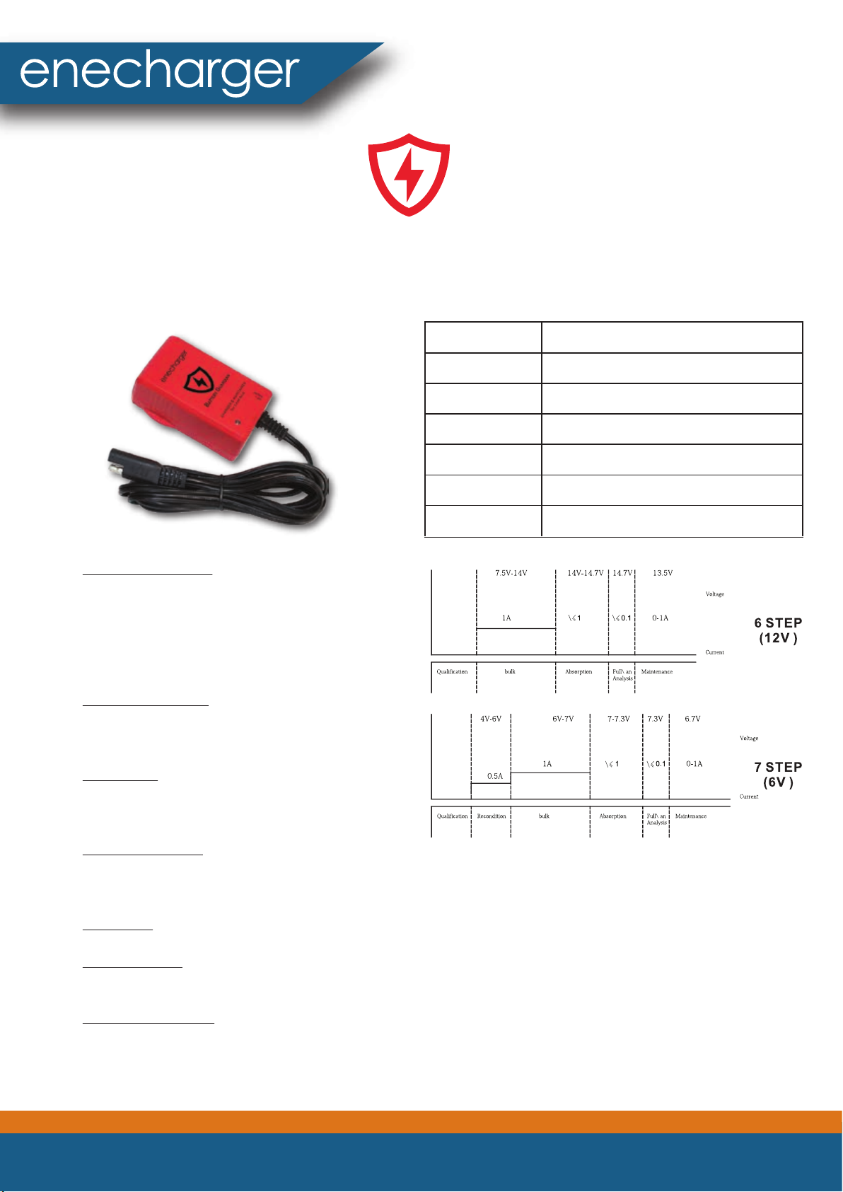
12. CHARGING PROGRAMS AND CURVES
Step 1. Qualication
Ensure the battery is in good condition prior to
charge. Charger will not start if battery is less
than 4V (6V system). If charger detects the
battery is slightly fatigue with minor sulphated
condition, it will rejuvenate and recover the
battery back to its peak performance.
Step 2. Recondition
Recondition follows when the qualication mode
is completed, it aims to re-activate the element of
battery for battery charging condition.
Step 3. Bulk
The normal charge is commenced to deliver the
constant current for charging up the battery until
80% full.
Step 4. Absorption
The charge program has switched over to
constant voltage; the charge current has to be
reduced according to the rise of battery charge level, until the battery is full.
Step 5. Full
The charge will stop once the battery is 100% charged.
Step 6. Analysis
It checks the battery voltage after charged, to make sure the voltage can be retained. Otherwise, the
battery is classied as a dead battery
Step 7. Maintenance
(fully charged) - Maintaining the battery voltage at maximum level by providing a constant voltage
charge. The battery can be permanently maintained at a proper work level and to be kept ready to go.
ICS1 Manual
3

GUARDIAN
BAT TERY
13. CHARGING TIMES.
The estimated time to charge a battery is shown
below. The size of the battery (Ah) and its depth of
discharge (DOD) greatly aect its charging time. The
charge time is based on an average depth of
discharge to a fully charged battery and is for
reference purposes only. Actual data may dier due
to battery conditions. The time to charge a normally
discharged battery is based on a 50% DOD.
Battery Size
(Ah)
Approx. Time to charge in hours.
6V
12V
2
2.6
2.6
4
5.2
5.2
8
10.4
10.4
10
13.0
13.0
15
19.5
19.5
20
26.0
26.0
Input Voltage AC
:
100-240 VAC, 50-60Hz
Working Voltage AC:
85-264 VAC
,
47
-
63Hz
Efficiency:
80
%
Approx
.
Power:
19W Max
Charging Voltage:
6V/12V
Charging Current:
1A
Low-Voltage Detection:
7.5V(12V), 4V(6V)
Back Current Drain:
<2mA
Ambient Temperature :
-10°C to 45°C
Charger Type:
7 Step, Smart Charger
Type of Batteries:
6V & 12V
Battery Chemistries:
Wet, Gel, MF
,
VRLA and AGM
Battery Capacity:
4-20Ah (12V), 4-20Ah (6V),
Maintains up to 100Ah
Housing Protection:
IP20
Cooling:
Natural Convection
Dimensions (L x W x H):
84X49.3X32mm
Weight:
0
.
25
/
0
.
3kg with box
14. TECHNICAL SPECIFICATIONS
15. WARRANTY INFORMATION & PROCEDURE:
If this product is in any way defective (other than resulting from abnormal use) within the stated period,
you can, at your cost, return it (with its original packaging if possible) with purchase receipt to the place of
of a Return Goods Authority Number.
Our goods come with guarantees that cannot be excluded under the Australian Consumer Law. You are
entitled to a replacement or refund for a major failure and for compensation for any other reasonably
foreseeable loss or damage. You are also entitled to have the goods repaired or replaced if the goods fail
to be of acceptable quality and the failure does not amount to a major failure. The benets under this
warranty are in addition to other rights you may have at law.
This warranty against defects is provided by the import agent Master Instruments Pty Ltd: 13 Sheridan
Close Milperra NSW 2214.
ICS1 Manual
4

GUARDIAN
BAT TERY
16. THIS WARRANTY DOES NOT COVER THE FOLLOWING:
• Failure resulting from misuse, accident, modication, unsuitable physical or operating
environment, or improper maintenance by you.
• Failure caused by a product for which our company is not responsible; and any non our company
approved products.
The warranty is voided by removal or alternation of identication labels on the device or its parts.
17. THIS WARRANTY DOES COVER THE FOLLOWING:
• Any manufacture defects that are under normal operation circumstance.
For warranty claims or repair, please contact your local reseller or authorized distributor for further
information
18. WARRANTY CERTIFICATE.
Record the following information for safe keeping.
Product model
Purchase date
Dealer name
Dealer address
Dealer phone no.
Dealer email
ICS1 Manual
5
This manual suits for next models
2
Table of contents
Popular Batteries Charger manuals by other brands


Schumacher
Schumacher SF-2150MA owner's manual

VOLTCRAFT
VOLTCRAFT 20 20 09 operating instructions

Hartig+Helling
Hartig+Helling BL 506 operating instructions

Tuncmatik
Tuncmatik FLIPCHARGER user manual

Team Check-point
Team Check-point TC-1030 instruction manual

BATTERIES PLUS
BATTERIES PLUS X2 POWER SLC10002A instruction manual


