Eneo AK-4 User manual

Quick installation guide
Camera junktion box
for Candid Small, Medium and Large
AK-4
DE
EN
FR
PL
RU

22
Inhalt
Sicherheitshinweise .................................................................................................3
Lieferumfang .............................................................................................................3
Beschreibung der Teile...........................................................................................4
Installationsanleitung...............................................................................................5
Montage.....................................................................................................................5
Kameramontage.......................................................................................................6
Bei Verwendung der M20x15 Kabelverschraubungen ............................6
Bei Verwendung der rückseitigen Kabeleinführung .................................6
Netzteilmontage........................................................................................................7
Kameraanschluss ....................................................................................................7

3
DE
EN
FR
PL
RU
3
DE
EN
FR
PL
RU
• 1x Anschlusskasten AK-4
• 1x Kurzanleitung
• 1x Sicherheitshinweise
• 1x 4 mm Inbusschlüssel
• 1x 3 mm Inbusschlüssel
• 4x Dübel
• 4x Wandbefestigungsschraube
• 4x Inbusschraube M4x20 für Candid Small, Medium, Large
• 4x Inbusschraube M5x16 für Candid Large (Wandarm rund)
• 4x M5 Unterlegscheibe für Candid Large (Wandarm rund)
• 3x M20x1,5 Kabelverschraubung
• 3x M20x1,5 Verschlusskappe
• 3x Dichtung
• 1x Membrantülle 32 mm
• 2x Kabelbinder
• 2x Dichteinsatzstopfen 5,5 mm / 6,2 mm
• 1x Dichteinsatzstopfen 2,7 mm
• 1x Netzteil-Befestigungsbügel
• 1x M4x6 Schraube für Netzteil-Befestigungsbügel
Lieferumfang
Sicherheitshinweise
Bitte beachten Sie auch die beiliegenden Sicherheitshinweise und lesen Sie
diese Anleitung vor Inbetriebnahme sorgfältig durch.
Wichtige Hinweise sind mit einem Achtungsymbol gekennzeichnet.
Bei der Montage muss grundsätzlich darauf geachtet werden, dass vorhan-
dene Dichtungen ordnungsgemäß eingesetzt und bei der Montage nicht
verschoben werden. Beschädigte Dichtungen dürfen nicht mehr verbaut
werden.

44
Beschreibung der Teile
ⓐⓑⓒⓓⓔⓕⓖⓗ
(i)
①Candid Medium / Large
(4mm)
② Candid Large (Wandarm rund)
(5mm)
③Candid Small (4mm)
①
②
③

5
DE
EN
FR
PL
RU
5
DE
EN
FR
PL
RU
Der Anschlusskasten kann wahlweise über die 3 M20x1,5 Kabel-
verschraubungen, oder die Kabeleinführung an der Rückseite
angeschlossen werden. Auch eine Kombination ist möglich. Bitte
beachten Sie die jeweiligen Montage Hinweise und verschließen Sie die
nicht benötigten Öffnungen mit den M20x1,5 Verschlusskappen!
Installationsanleitung
Montage
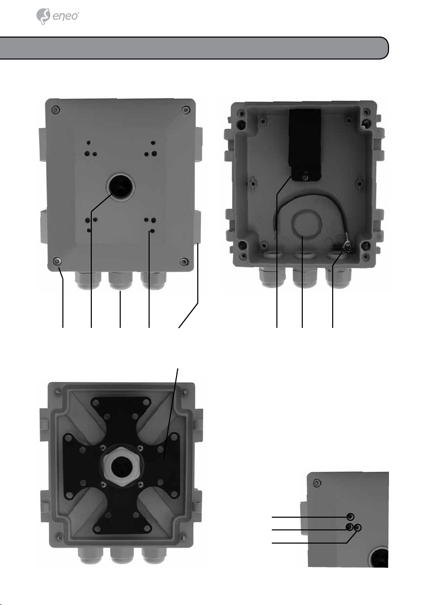
ⓐGehäusedeckelschrauben
ⓑVerschraubung M25 mit Dichteinsatz
ⓒKabelverschraubung M20x15
ⓓKamera Schraubgewinde für Candid Small, Medium und Large Serie
ⓔScharnier
ⓕNetzteilhalteklammer
ⓖDurchbruch bei Verwendung der Membrantülle
ⓗErdungsanschluss
ⓘAbdeckplatte der Kabelwickelvorrichtung

66
Kameramontage
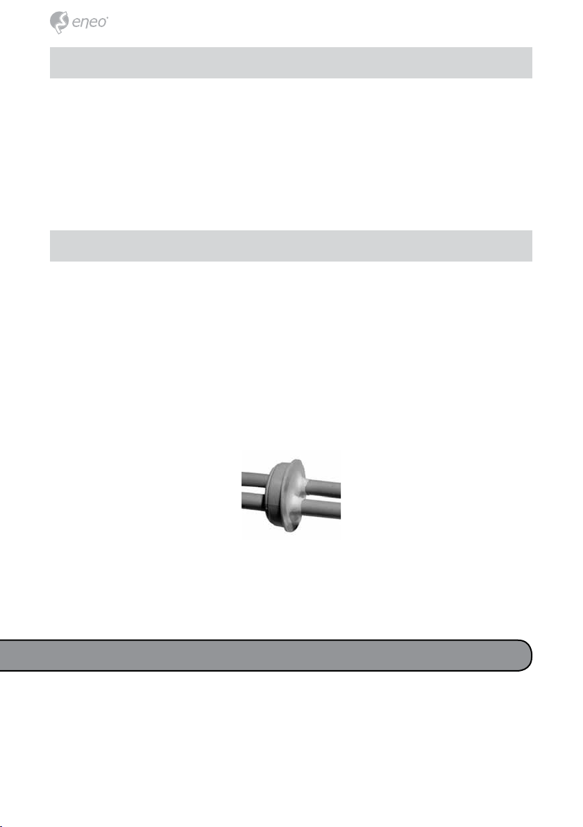
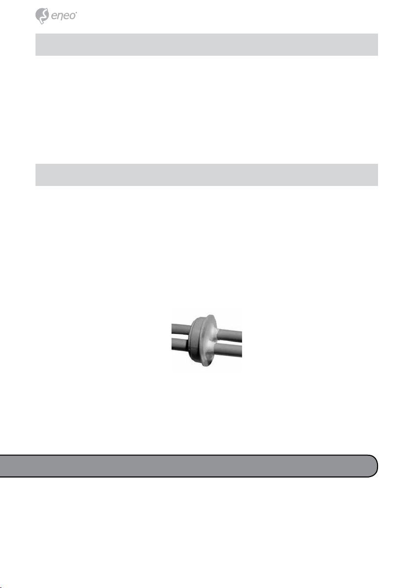
1) Entfernen Sie den Durchbruch aus der Rückseite des Anschlusskastens.
Entgraten Sie die Bruchkante mit einer Feile und drücken Sie die Membran-
tülle von der Rückseite in die Öffnung.
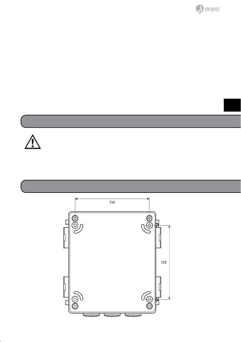
2) Bohren Sie die Wandlöcher entsprechend der in der Zeichnung ange-
gebenen Abstände. Achten Sie dabei auf die richtige Positionierung der
Kabeleinführung!
3) Stecken Sie die Dübel in die gebohrten Löcher.
4) Stechen Sie für jedes Kabel ein separates Loch in die Membran und
führen Sie die Kabel durch die Dichtung in den Anschlusskasten.
5) Positionieren Sie den Anschlusskasten auf den Bohrlöchern.
6) Befestigen Sie den Anschlusskasten mit den Wandbefestigungsschrau-
ben.
Bei Verwendung der rückseitigen Kabeleinführung
1) Bohren Sie die Wandlöcher entsprechend der in der Zeichnung angege-
benen Abstände.
2) Stecken Sie die Dübel in die gebohrten Löcher.
3) Positionieren Sie den Anschlusskasten auf den Bohrlöchern.
4) Befestigen Sie den Anschlusskasten mit den Wandbefestigungsschrau-
ben.
Bei Verwendung der M20x15 Kabelverschraubungen
1) Entfernen Sie das Verschraubungsoberteil und den Dichteinsatz aus der
im Deckel befindlichen Kabeleinführung.
2) Führen Sie die Kabel von Außen durch die Verschraubung und die Ver-
schlusskappe.
7
DE
EN
FR
PL
RU
7
DE
EN
FR
PL
RU
3) Stecken Sie die Kabel über die seitlichen Einschnitte in die passenden
Löcher des Dichteinsatzes. Verschließen Sie die nicht genutzten Löcher mit
den beiliegenden Dichteinsatzstopfen.
4) Verschrauben Sie die Kamera auf dem Deckel und schieben Sie den
Dichteinsatz in die Verschraubung. Dichten Sie die Öffnung durch das An-
ziehen der Verschlusskappe ab.
5)Legen Sie die Kabel parallel und wickeln Sie diese auf die Spulvorrich-
tung auf. Fixieren Sie die Kabel mit den beiliegenden Kabelbindern.
Zur Verwendung des Netzteils VT-PS12DC-12 (separat erhältlich) setzen
Sie das Netzteil ein und fixieren Sie es anschließend mit der Halteklemme
und der dazugehörigen Schraube.
Durch das Einsetzen des Netzteils verringert sich der verfügbare
Innenraum. Dies muss bei der Verwendung der Kabelwickelvor-
richtung entsprechend berücksichtigt werden.
Netzteilmontage
Schließen Sie die Kamera über die Kabeleinführung an der Rückseite, oder
die M20x15 Kabelverschraubungen, an. Prüfen Sie den korrekten Sitz der
Dichtungen und schließen Sie den Anschlusskasten. Fixieren Sie den De-
ckel durch Festziehen der Schrauben.
Kameraanschluss

8

9
DE
EN
FR
PL
RU
• 1x Terminal box AK-4
• 1x Quick installation guide
• 1x Notes on safety
• 1x 4 mm Allen key
• 1x 3 mm Allen key
• 4x Wall plug
• 4x Wall fixing screws
• 4x Hexagonal screw M4x20
• 4x Hexagonal screw M5x16
• 4x M5 Plain washer
• 3x M20x1.5 Screwed cable gland
• 3x M20x1.5 Screwed cable gland
• 3x Seal
• 1x Membrane bushing 32 mm
• 2x Cable tie
• 2x Waterproof stopper 5.5 mm / 6.2 mm
• 1x Waterproof stopper 2.7 mm
• 1x Power supply fastening bow
• 1x M4x6 Screw for power supply fastening bow
Scope of delivery
Notes on Safety
Please also pay attention to the enclosed notes on safety, and carefully
read through this instruction guide before initial operation.
Important points of advice are marked with a caution symbol.
During installation, always ensure that the supplied seals are correctly
inserted and have not been nudged out of position. Damaged seals may no
longer be utilised.

10
Description of parts
(a) (b) (c) (d) (e) (f) (g) (h)
(i)
①Candid Medium / Large
(4mm)
② Candid Large (round bracket)
(5mm)
③Candid Small (4mm)
①
②
③

11
DE
EN
FR
PL
RU
The terminal box can be connected using the 3 M20x1.5 screw
fittings, or optionally with the cable entry on the rear side. A
combination using both is also possible. Please pay attention to
the relevant assembly notes, and seal all of the unused openings with the
M20x1.5 caps!
Installation instruction
Assembly
(a) Container lid screws
(b) Screw fitting M25 with waterproof insert
(c) Screwed cable gland M20x15
(d) Camera screw thread for Candid Small and Medium series
(e) Hinge
(f) Power supply retaining clip
(g) Push-through hole for use with the membrane bushing
(h) Earth connection point
(i) Cabling cover plate
12
Camera assembly
1) Remove the push-out on the rear-side of the terminal box.
Trim the edge of the hole with a file, and press the membrane bushing into
the opening from the rear-side.
2) Drill the wall holes in accordance with the distances specified in the dra-
wing. Whilst doing this, pay attention to the correct positioning of the cable
entry!
3) Insert the wall plugs into pre-drilled holes.
4) Puncture the membrane for each separate cable and feed the cables
through the seal into the terminal box.
5) Position the terminal box over the bore holes.
6) Secure the terminal box with the wall fixing screws.
When using the rear-side cable entry
1) Drill the wall holes in accordance with the distances specified in the
drawing.
2) Insert the wall plugs into pre-drilled holes.
3) Position the terminal box over the bore holes.
4) Secure the terminal box with the wall fixing screws.
When using the M20x15 screw fittings
1) Remove the upper screw part and the seal insert from cable entry found
in the lid.
2) Feed the cable from outside through the screw connection and the cap.
3) Insert the cable via the lateral slot into the matching hole of the seal.

13
DE
EN
FR
PL
RU
Seal the unused holes with the supplied waterproof stoppers.
4) Screw the camera to the lid and push the seal into the screw connection.
Seal the opening by pulling on the cap.
5) Lay the cable parallel and wrap it around the winder. Secure the cables
with the supplied cable ties.
To make use of the VT-PS12DC-12 Power Supply (available separately)
insert the power supply and secure the power supply to the relevant screw
using the retaining clip thereafter.
Power supply assembly
Connect the camera via the rear-side cable entry, or with the M20x15 screw
cable gland. Check that the seals are sitting correctly and close the termi-
nal box. Secure the lid by tightening the screws.
Camera connection

1414
15
DE
EN
FR
PL
RU
15
DE
EN
FR
PL
RU
• 1x boîtier de raccordement AK-4
• 1x guide d’installation rapide
• 1x consignes de sécurité
• 1x clé six pans mâle 4 mm
• 1x clé six pans mâle 3 mm
• 4x chevilles
• 4x vis de fixation murale
• 4x vis à tête creuse M4x20
• 4x vis à tête creuse M5x16
• 4x rondelles M5
• 3x raccords à visser pour câble M20x1,5
• 3x bouchons M20x1,5
• 3x joints
• 1x passe-câble à membrane 32 mm
• 2x attache-câbles
• 2x bouchons d’étanchéité 5,5 mm / 6,2 mm
• 1x bouchon d’étanchéité 2,7 mm
• 1x étrier de fixation pour bloc secteur
• 1x vis M4x6 pour étrier de fixation bloc secteur
Contenu
Consignes de sécurité
Respectez les consignes de sécurité ci-après et lisez attentivement cette
notice avant toute utilisation.
Les remarques importantes sont identifiées par le symbole «
Attention ».
Lors du montage, il est impératif de veiller à ce que les joints existants soi-
ent placés correctement et ne glissent pas pendant le montage. Les joints
endommagés ne doivent plus être utilisés.
1616
Description des pièces
(a) (b) (c) (d) (e) (f) (g) (h)
(i)
①Candid Medium / Large
(4mm)
② Candid Large (Wandarm rund)
(5mm)
③Candid Small (4mm)
①
②
③
17
DE
EN
FR
PL
RU
17
DE
EN
FR
PL
RU
Le boîtier de raccordement peut être raccordé au choix à l’aide
des 3 raccords à visser pour câble M20x1,5 ou du passe-câble
situé à l’arrière. Une combinaison des deux est également possib-
le. Respectez les instructions de montage correspondantes et obturez les
ouvertures non utilisées à l’aide des bouchons M20x1,5.
Instructions d’installation
Montage
(a) Vis du couvercle du boîtier
(b) Raccord à visser M25 avec joint
(c) Raccord à visser pour câble M20x15
(d) Pas de vis caméra pour Candid série Small et Medium
(e) Charnière
(f) Patte de fixation pour bloc secteur
(g) Passage en cas d’utilisation du passe-câble à membrane
(h) Mise à la terre
(i) Plaque de recouvrement de l’enrouleur de câble
1818
Montage de la caméra
1) Retirez l’opercule à l’arrière du boîtier de raccordement.
Ébavurez les bordures à l’aide d’une lime et enfoncez le passe-câble à
membrane par l’arrière dans l’ouverture.
2) Percez les trous dans le mur en respectant les cotes indiquées sur le
schéma. Faites attention de bien positionner le passage des câbles.
3) Placez les chevilles dans les trous percés.
4) Percez un trou distinct pour chaque câble dans la membrane et faites
passer les câbles à travers le joint dans le boîtier de raccordement.
5) Positionnez le boîtier de raccordement sur les trous percés.
6) Fixez le boîtier de raccordement à l’aide des vis de fixation murale.
En cas d‘utilisation du passe-câble arrière
1) Percez les trous dans le mur en respectant les cotes indiquées sur le
schéma.
2) Placez les chevilles dans les trous percés.
3) Positionnez le boîtier de raccordement sur les trous percés.
4) Fixez le boîtier de raccordement à l’aide des vis de fixation murale.
En cas d’utilisation des raccords à visser pour câble M20x15
1) Retirez la partie supérieure du raccord à visser et le joint du passage de
câble qui se trouve dans le couvercle.
2) Introduisez les câbles par l’extérieur dans le raccord à visser et le bou-
chon.

19
DE
EN
FR
PL
RU
19
DE
EN
FR
PL
RU
3) Faites passer les câbles par les ouvertures latérales dans les trous
correspondants du joint. Fermez les trous non utilisés avec les bouchons
d’étanchéité fournis.
4) Vissez la caméra sur le couvercle et glissez le joint dans le raccord à
visser. Serrez le bouchon pour rendre l’ouverture étanche.
5) Placez les câbles en parallèle et déroulez l‘enrouleur. Fixez les câbles à
l’aide des attache-câbles fournis.
Pour utiliser le bloc secteur VT-PS12DC-12 (fourni séparément), insérez le
bloc secteur et fixez-le ensuite à l’aide de la patte de fixation et de la vis
correspondante.
Montage du bloc secteur
Raccordez la caméra via le passe-câble situé à l’arrière ou des raccords à
visser pour câble M20x15. Assurez-vous que les joints sont bien placés et
fermez le boîtier de raccordement. Fixez le couvercle en serrant les vis à
fond.
Raccordement de la caméra

2020
Table of contents
Languages:
Other Eneo Industrial Electrical manuals

Popular Industrial Electrical manuals by other brands


Murata
Murata GRM1555C1E4R4CA01 Series Reference sheet

hager
hager EPN051 User instructions

Murata
Murata GRM0225C1E9R1CA03 Series Reference sheet

Murata
Murata GRM0335C1H7R9CA01 Series Reference sheet

Murata
Murata GRM1555C1H5R2DA01 Series Reference sheet

Murata
Murata GRM0335C1ER30BA01 Series Reference sheet

Murata
Murata GRT21BR61C475MA02 Series Reference sheet

Murata
Murata GRM0225C1E4R0WA03 Series Reference sheet

Murata
Murata GCM1885G1H101JA16 Series Reference sheet

GE
GE THQ Series Homeowner & Installer Information

Belden
Belden FX Fusion Splicer user manual

Murata
Murata GCM188R71E332KA37 Series Reference sheet