Enerdrive ePro Plus User manual
Owner’s Manual
High Precision Module Battery Monitor
Enerdrive ePRO Plus Battery Monitor Owner’s Manual (Rev. 1.03) January 2019

Enerdrive ePRO Plus Battery Monitor Owners Manual (Rev. 1.03)Page 2
Notice of Copyright
ePRO Plus owner’s manual © 2019 Enerdrive Pty Ltd. All rights reserved. No part of this document
may be reproduced in any form or disclosed to third parties without the express written permission
of Enerdrive 11 Millennium Place, Tingalpa, Queensland, Australia 4173. Enerdrive reserves the
right to revise this document and to periodically make changes to the content hereof
without obligation or organization of such revisions or changes, unless required to do so by
prior arrangement.
Exclusions for documentation and product usage
UNLESS SPECIFICALLY AGREED TO IN WRITING, Enerdrive:
1.
Makes no warranty as to the accuracy, su ciency or suitability of any technical or other
information provided in its manuals or other documentation
2.
Assumes no responsibility or liability for losses, damages, costs or expenses, whether
special, direct, indirect, consequential or incidental, which might arise out of the use of such
information. The use of any such information will be entirely at the user’s risk
3.
Makes no warranty, either expressed or implied, including but not limited to any implied
warranties of merchantability or tness for a particular purpose, regarding these Enerdrive
products and makes such Enerdrive products available solely on an “as is” basis.
4.
Shall in no event be liable to anyone for special, collateral, incidental, or consequential damages
in connection with or arising out of purchase or use of these Enerdrive products. The sole and
exclusive liability to Enerdrive, regardless of the form of action, shall not exceed the purchase
price of the Enerdrive products described here in.

www.enerdrive.com.au Page 3
Table Of Contents
1. INTRODUCTION .............................................................................................. 5
1.1 General ....................................................................................................................................5
1.2 Box Contents.........................................................................................................................5
1.3 Why A Battery Should Be Monitored ...........................................................................5
1.4 ePRO Plus Highlights..........................................................................................................6
1.5 CDU Display And Control Overview .............................................................................6
1.6 Active Shunt Status Indicator..........................................................................................7
2. QUICKSTART ................................................................................................... 9
2.1 General ....................................................................................................................................9
2.2 Setup wizard .........................................................................................................................9
3. NORMAL OPERATING MODE......................................................................... 12
3.1 Overview Of Parameter Readouts.................................................................................12
3.2 Display Messages ................................................................................................................14
3.3 Synchronization...................................................................................................................15
4. STATUS MENU ................................................................................................. 16
5. HISTORY MENU............................................................................................... 18
6. FUNCTION SETUP MENU ............................................................................... 19
6.1 Battery Bank 1 (Main) Properties....................................................................................19
6.2 Battery Bank 2 Properties.................................................................................................21
6.3 Battery Bank 3 Properties.................................................................................................22
6.4 System Properties ...............................................................................................................23
6.5 Alarm Properties..................................................................................................................23
6.6 Display Properties ...............................................................................................................27
6.7 Global Properties.................................................................................................................28
6.8 Advanced Properties..........................................................................................................28

Enerdrive ePRO Plus Battery Monitor Owners Manual (Rev. 1.03)Page 4
7. RESET MENU ................................................................................................... 31
8. LOCK MENU..................................................................................................... 32
8.1 Locking The ePRO Plus ......................................................................................................32
8.2 Unlocking The ePRO Plus .................................................................................................32
9. TROUBLESHOOTING GUIDELINE.................................................................. 33
10. TECHNICAL SPECIFICATIONS........................................................................ 35
11. WARRANTY CONDITIONS.............................................................................. 37
12. DECLARATION OF CONFORMITY ................................................................. 38
13. APPENDIX 1: .................................................................................................... 39
Measuring The Midpoint Voltage Of A 24V Or 48V Battery Bank .............................39
Wiring .............................................................................................................................................39
Practical Information.................................................................................................................41

www.enerdrive.com.au Page 5
1. INTRODUCTION
1.1 General
Thank you for purchasing the Enerdrive ePRO Plus battery monitor. Please read this owner’s
manual and the supplied installation guide for information about using the product correctly
and safely. Keep this owner’s manual and all other included documentation close to the product
for future reference.
For the most recent manual revision and added content, please check the Downloads section
on our website at: http://www.enerdrive.com.au/product/epro-plus-battery-monitor/
The purpose of this owner’s manual and the installation guide is to provide explanations and
procedures for installing, con guring and operating the battery monitor. The installation
instructions are intended for installers that should have knowledge and experience in installing
electrical equipment, knowledge of the applicable installation codes, and awareness of the
hazards involved in performing electrical work and how to reduce those hazards.
1.2 Box Contents
• The box should contain the following items:
• Active shunt module
• Display and Control Unit (CDU)
• Fused supply cable
• Shunt to CDU cable
• Bag with rubber port covers
• This owner’s manual
• Installation guide
Please contact your supplier when any of these items show visual damage or when some items
are missing.
1.3 Why A Battery Should Be Monitored
Operating your battery bank without good metering is like running your car without any gauges,
although possible to do, it’s always better to know how much fuel is left in the tank.
De ning the amount of energy available in a battery is a complex task, since battery age, discharge
current and temperature all in uence the actual battery capacity. The ePRO Plus is equipped with
high performance measuring circuits and complex software algorithms, to exactly determine
the remaining battery capacity.
Besides o ering an accurate state of charge indication, the ePRO Plus will also help users how
to get the best service life out of the battery bank. The service life of batteries will be negatively
aected by excessive deep discharging, under- or overcharging, excessive charge- or discharge
currents and/or high temperatures. The user can detect such abuse easily through the clear display
of the ePRO Plus. Or alarms can be triggered when certain limits are exceeded, so that immediate
measures can be taken. All this to extend the battery’s lifetime and save costs in the long term.

Enerdrive ePRO Plus Battery Monitor Owners Manual (Rev. 1.03)Page 6
1.4 ePRO Plus Highlights
The ePRO Plus is our latest generation, highly advanced battery monitor. It consists of an intelligent
active shunt and a remote control and display unit (CDU). The shunt has a Grid Optimized footprint
for perfect integration with our DC Modular series of high current busbars and fuse holders.
This advanced battery monitor not only shows the true state of charge of your battery system.
It also o ers a large amount of additional features to optimally supervise your battery system
and control external equipment. The ePRO Plus is compatible with lead based and Lithium
(LiFePO4) based batteries.
The ePRO Plus can monitor up to three battery banks. The inputs for battery bank 2 and 3 can
also be con gured for other purposes, like mid-point voltage measurement, key switch input
or back light control. The ePRO Plus battery monitor can measure DC currents up to 600Amps
(500Amp continuous) and voltages up to 70Vdc. So any lead- or lithium based battery from 12V
up to 48V can be monitored.
The installation time is minimal, requiring only one supply wire to the intelligent shunt base and a
single plug and play ‘QLINK’ (QuickLink) cable between the active shunt and the CDU. Furthermore,
the battery minus cable must be interrupted in order to insert the shunt into the high current
circuit. The ePRO Plus is equipped with two QLINK bus ports. In the simplest setup, only one of
the QLINK ports will be used to connect to the CDU. However, more optional accessories can be
installed by employing the second QLINK port. Such accessories are for example communication
interfaces or an alarm output expander box.
1.5 CDU Display And Control Overview
Please see the image and information below for an overview of the display contents and the
controls.
www.enerdrive.com.au Page 7
1. Left key (<) or Previous value
2. Menu or Enter key
3. Right key (>) or Next value
4. 7 character multipurpose information eld
5. Alarm indicator
6. Selected battery input indicator
7. Value section for SoC (also for Function, Status and History parameter numbers)
8.
State of Charge (SoC) bar. The ve segment 0 – 100% grid will show an animation when there
is a charge current (turning clockwise) or a discharge current (turning counter clockwise). The
animation speed will also increase when the charge or discharge current increases.
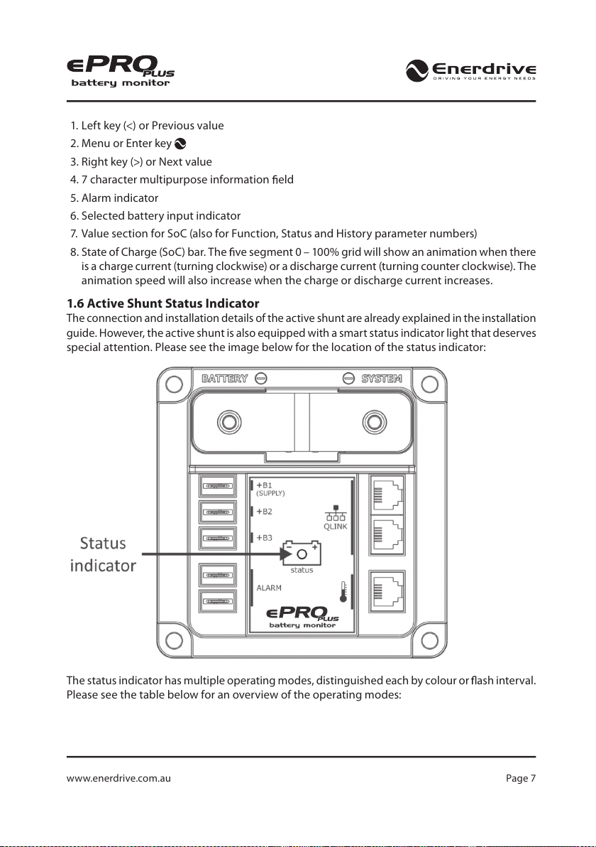
1.6 Active Shunt Status Indicator
The connection and installation details of the active shunt are already explained in the installation
guide. However, the active shunt is also equipped with a smart status indicator light that deserves
special attention. Please see the image below for the location of the status indicator:
The status indicator has multiple operating modes, distinguished each by colour or ash interval.
Please see the table below for an overview of the operating modes:

Enerdrive ePRO Plus Battery Monitor Owners Manual (Rev. 1.03)Page 8
Table 1
Status colour Status ash interval1Description
Green Slow Main battery healthy (SoC > 50%)
Orange Slow Main battery needs to be recharged (SoC
= 30 – 50%)
Red Slow Main battery empty, recharge now (SoC
< 30 %)
Red Fast Error
Orange Fast Initializing
Status ash interval times are 2 seconds for ‘Slow’ and 0.5 seconds for ‘Fast’
www.enerdrive.com.au Page 9
2. QUICKSTART
2.1 General
This chapter describes the minimum amount of steps that need to be followed in order to
get your ePRO Plus up and running. It assumes that the enclosed installation guide has been
followed carefully and that the ePRO Plus is powered up for the rst time. After this the Setup
wizard will start automatically. If the Setup wizard does not start and the ePRO Plus will jump to
the normal operating mode after power up, it has already been con gured before. In that case
you can choose to restore the factory default settings (see chapter 7, for more information) and
start from the beginning. Please see the next chapter for more details about the Setup wizard.
2.2 Setup wizard
The Setup wizard will guide you through a few basic steps that are essential for a correctly
functioning ePRO Plus. No other Function settings can be accessed before the Setup wizard
has been completed.
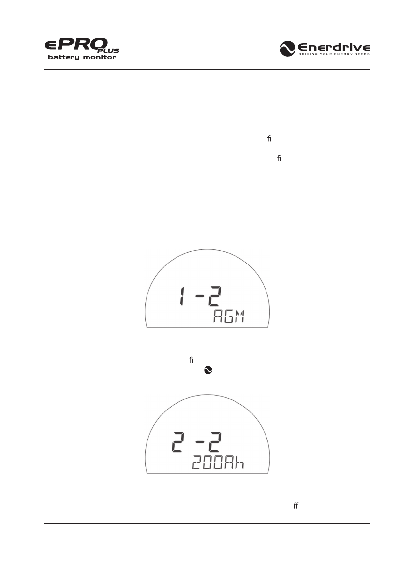
Step 1-2: Main battery type
The display will start by showing the battery type selection screen. You can use the left (<) and
right (>) arrow keys to select between AGM (default), GEL, Flooded and Lithium LiFePO4. Please
consult your battery manual or supplier, to nd out the correct type of your battery system. Once
the selection has been made, press the MENU key to jump to the next step.
Step 2-2: Main battery capacity
The default battery capacity value is 200Ah. This can be changed by pressing the left or right
arrow keys until the desired value is reached. The standard battery capacity value is based on
a discharge rate of 20 hours. When your battery capacity is rated at a di erent discharge rate,

Enerdrive ePRO Plus Battery Monitor Owners Manual (Rev. 1.03)Page 10
please change this in Function F1.2 (see chapter 6.1) afterwards. Once the selection has been
made, press the MENU key for 3 seconds to nalize the Setup wizard.
If you wish to make any changes to the Main battery type or capacity afterwards, you
can always edit Functions F1.0 and F1.1 (see chapter 6.1).
The Setup wizard does not include any con guration steps for battery banks connected
to the B2 and B3 inputs. If your system does include a second or third battery, please
con gure these manually using Functions F2 and F3 (see chapter 6.2 and 6.3).
After the Setup wizard has been completed, the ePRO Plus will take a few seconds to analyze
your battery and estimate the nominal battery voltage as well as the current State of Charge (%).
The State of Charge readout will show a small animation while it is calculating.
When a lithium battery type is selected, only the nominal battery voltage will be
estimated. A start value for the State of Charge is not given yet and represented by
‘- - %‘. A complete charge cycle is needed to obtain the exact State of Charge value.
For the highest accuracy, it is important that the battery is not being charged or
discharged during this analysis time!
When your battery system has a nominal voltage level other than listed in table 2, you need to
manually change this in Advanced Function A07.
Table 2 shows how the ePRO Plus determines the nominal voltage of your battery bank. This
table is valid for all three battery bank inputs. Please note however, that inputs +B2 and +B3 do
not support LiFePO4 batteries. As you can see in table 2, the estimated number of battery cells
are also mentioned. Except for individual 2V lead- or 3V Lithium cells, all batteries contain a
number of internal cells in series. A 12V lead acid battery for example, contains 6 cells internally.
The ePRO Plus needs to know the number of cells, since its calculation algorithms are cell based
for optimal accuracy.
Table 2
Measured voltage
Assumed nominal voltage for
lead based battery (number
of internal cells)
Assumed nominal voltage
for LiFePO4 based battery
(number of internal cells)
Vbatt < 5.0V - -

www.enerdrive.com.au Page 11
5.0 < Vbatt < 7.5V 6V (3 cells) 6V (2 cells)
7.5 < Vbatt < 10.0V 6V (3 cells) 9V (3 cells)
10.0 < Vbatt < 15.0V 12V (6 cells) 12V (4 cells)
15.0 < Vbatt < 20.0V 18V (9 cells) 18V (6 cells)
20.0 < Vbatt < 30.0V 24V (12 cells) 24V (8 cells)
30.0 < Vbatt < 40.0V 36V (18 cells) 36V (12 cells)
VBatt > 40.0V 48V (24 cells) 48V (16 cells)
Once the ePRO Plus shows the estimated state of charge value, it is now ready for use! Over time,
it will keep on learning your battery and the estimated state of charge will become increasingly
more accurate.

Enerdrive ePRO Plus Battery Monitor Owners Manual (Rev. 1.03)Page 12
3. NORMAL OPERATING MODE
3.1 Overview Of Parameter Readouts
In normal operating mode, the ePRO Plus can show you a wide range of important battery
parameters. Each parameter can be accessed by pressing the left or right arrow keys. The main and
most important parameter is the State of Charge (SoC) in %. This value will always be displayed
and is also linked to the round bar graph at the outer edge of the display. Additionally, the ePRO
Plus can show a second parameter at the bottom row of the display.
By default, the parameters voltage, current, time remaining and temperature are enabled
with temperature only shown when an optional temperature sensor is connected. Additional
parameters that are disabled by default are power and Amp-hours. The visibility of individual
parameters can be enabled or disabled through functions F9.0 to F9.8.
The default settings will allow the second parameter to only show for 120 seconds after the ePRO
Plus has been accessed. This will keep the display clean under normal conditions, which might
be preferred by less technical end users. Function F9.9 sets the second parameter auto hide time
and also o ers an option to always show the second parameter (auto hide =OFF).
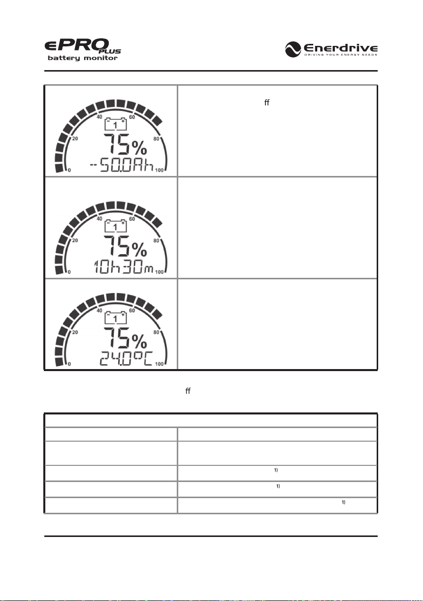
Table 3 shows all available parameter readouts:
Table 3
State of charge (SoC) (%)
The SoC is the most important battery parameter. It
shows exactly how much charge is left in the battery.
This value is compensated for all known battery variables
(age, charge/discharge current, temperature etc.). 100%
represents a fully charged battery, while 0% represents
a completely at battery. Typically, you should recharge
a lead based battery when the SoC has dropped below
50%. For a lithium based battery, this level can be lower.
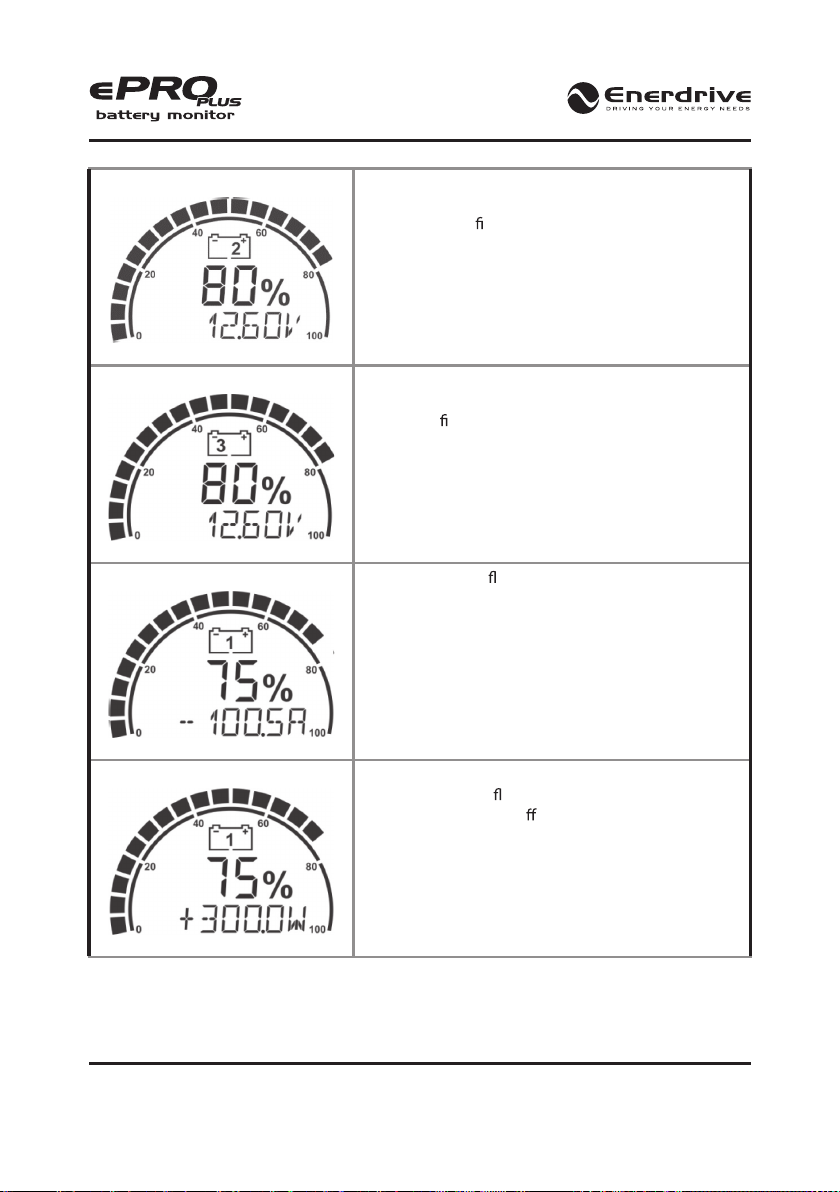
Main battery voltage (V)
Shows the voltage of the main battery bank connected
to the +B1 input.
www.enerdrive.com.au Page 13
Battery bank 2 voltage (V)
Shows the voltage of battery bank 2 (connected to
the +B2 input). This value will only be shown when the
+B2 input is con gured as a second battery input (see
Function F2.0).
Battery bank 3 voltage (V) Shows the voltage of battery bank 3 (connected to the
+B3 input). This value will only be shown when the +B3
input is con gured as a third battery input (see Function
F3.0).
Main battery current (A)
Shows the current owing in- or out of the main battery.
A negative sign indicates a discharge current and a
positive sign a charge current.
Main battery power (W)
Shows the power draw from the main battery (negative
sign) or the power ow into the battery (positive sign).
This reading is turned o by default and can be turned
on in Function F9.2.
Enerdrive ePRO Plus Battery Monitor Owners Manual (Rev. 1.03)Page 14
Main battery Amp-hours (Ah)
The amount of Amp-hours discharged from the battery.
This reading is turned o by default and can be turned
on in Function F9.3.
Main battery time remaining
(h:m)
Shows how much time is left under the present load,
before the battery needs to be recharged again.
Temperature (°C)
Shows the battery temperature when a temperature
sensor is connected to the ePRO Plus. The default
temperature unit is °C, but it can be set to °F as well in
Function F10.3.
3.2 Display Messages
The ePRO Plus can show a number of di erent status messages on the display. These will vary
from advisory- to error messages. Please see the table below for the available messages
Table 4
Message Explanation
‘<battery name> Battery Full’ The main battery is fully charged. ‘<battery name>’ will
be replaced by the name given in Function 1.7
‘Low Voltage’ Low battery voltage alarm
‘High Voltage’ High battery voltage alarm
‘Low Battery’ Low main battery State of Charge (SoC) alarm

www.enerdrive.com.au Page 15
‘Low Time Remaining’ Low time remaining alarm for main battery
‘High Charge Current’ High charge current alarm for main battery
‘High Discharge Current’ High discharge current alarm for main battery
‘Low Temperature’ Low temperature alarm for main battery
‘High Temperature’ High temperature alarm for main battery
‘High Midpoint Deviation’ High midpoint deviation alarm for main battery
The number inside the battery icon indicates to which battery the message applies
3.3 Synchronization
The ePRO Plus is a true next generation battery monitor that does not speci cally require a full
synchronization before you can actually use it (except for LiFePO4 batteries). The smart internal
algorithms can already estimate the state of charge by performing a short battery analysis at
start up. Unlike many other battery monitors on the market, the ePRO Plus will not get out of
sync easily when the battery is not being fully charged (synchronized) very often.
Nevertheless, for the highest State of Charge (SoC) readout accuracy, it is still advisable to regularly
synchronize the ePRO Plus with your battery. A synchronisation step means nothing more than
performing a complete charge cycle on your battery. The ePRO Plus will automatically detect
when a full charge cycle has been performed and resets the SoC value to 100%.
Performing full charge cycles regularly is also important to keep your battery healthy and to
increase its lifetime.
Besides automatic synchronisations, you can also manually synchronize the
battery monitor, when you are sure that your battery is fully charged. This can
be accomplished by pressing both left and right arrow keys simultaneously for
three seconds. After these three seconds, the SoC value will be reset to 100%.
For people who prefer to use the older auto synchronization method of the ePRO models, there
is an Advanced function setting (A01) available that can be set to ‘Legacy’ mode. After it has been
set to Legacy mode, all needed auto synchronization parameters will show up in the Advanced
properties list to modify if desired. See chapter 6.8 for more information.

Enerdrive ePRO Plus Battery Monitor Owners Manual (Rev. 1.03)Page 16
4. STATUS MENU
The Status menu is a read only menu that shows the current status of a number of ePRO Plus
items. This menu can be accessed by the following sequence:
When the Status menu is entered, you can use the left and right arrow keys to browse through
the di erent status items. By pressing the MENU key, the selected status item can be viewed.
Pressing the MENU key again, will step back to the Status menu. From any menu position, the
normal operating mode can be accessed again by pressing the MENU key for 3 seconds. The
ePRO Plus will also jump back to the normal operating mode automatically after 30 seconds,
when no keys are pressed during this time.
The following Status menu items are available:
Table 5
Status Item Status description
S 1.0 Name. Shows the name of this product.
S 1.1 Firmware version. Shows the rmware version of this product.
S 1.2 Hardware version. Shows the hardware version of this product.
S 1.3 Serial number. Shows the serial number of this product.
S 2.0 Alarm 1. Indicates if Alarm 1 is active.
S 2.1 Alarm 2. Indicates if Alarm 2 is active.

www.enerdrive.com.au Page 17
S 2.2 Alarm 3. Indicates if Alarm 3 is active.
S 2.3 Alarm 4. Indicates if Alarm 4 is active.
S 3.0 State of Health (SoH). Shows the SoH of your battery system.
S 3.1 Midpoint voltage. Shows the present midpoint voltage value.
S 3.2 Midpoint deviation. Shows the present midpoint deviation percentage
S 4.0 Total hours. Shows the number of hours that this product has been running.
S 4.1
Maintenance hours. Shows the number of hours left before maintenance is
required.
S 4.3
Hours since charged. Shows the number of hours since the battery has last
been charged.
S 4.4
Hours since synchronized. Shows the number of hours since the battery monitor
has last been synchronized with the main battery.

Enerdrive ePRO Plus Battery Monitor Owners Manual (Rev. 1.03)Page 18
5. HISTORY MENU
The History menu is a read only menu that shows the ePRO Plus’s History data. History data are
special events that are stored in internal memory. This menu can be accessed by the following
sequence:
When the History menu is entered, you can use the left and right arrow keys to browse through
the di erent History items. By pressing the MENU key, the selected History item can be viewed.
Pressing the MENU key again, will then step back to the History menu. From any menu position,
the Normal Operating Mode can be accessed again by pressing the MENU key for 3 seconds.
The following History menu items are available:
Table 6
History Item History description
H 1.0
Average discharge (Ah). Average discharge of your main battery in Ah.
This number will be recalculated after each synchronization.
H 1.1
Average discharge (%). Average discharge of your main battery in
percent. This number will be recalculated after each synchronization.
H 1.2
Deepest discharge (Ah). Deepest discharge of your main battery in Ah.
H 1.3 Deepest discharge (%). Deepest discharge of your main battery in %.
H 1.4
Total Ah removed. The total number of Amphours removed from the
main battery. When exceeding 999Ah, the units change to kAh and
the displayed value must be multiplied by 1000.
H 1.5
Total Ah charged. The total number of Amphours charged to the main
battery. When exceeding 999Ah, the units change to kAh and the
displayed value must be multiplied by 1000.
H 1.6
Total kWh removed. The total number of kWh removed from the main
battery. When exceeding 999kWh, the units are changed to MWh.
H 1.7
Total kWh charged. The total number of kWh charged to the main
battery. When exceeding 999kWh, the units are changed to MWh.
www.enerdrive.com.au Page 19
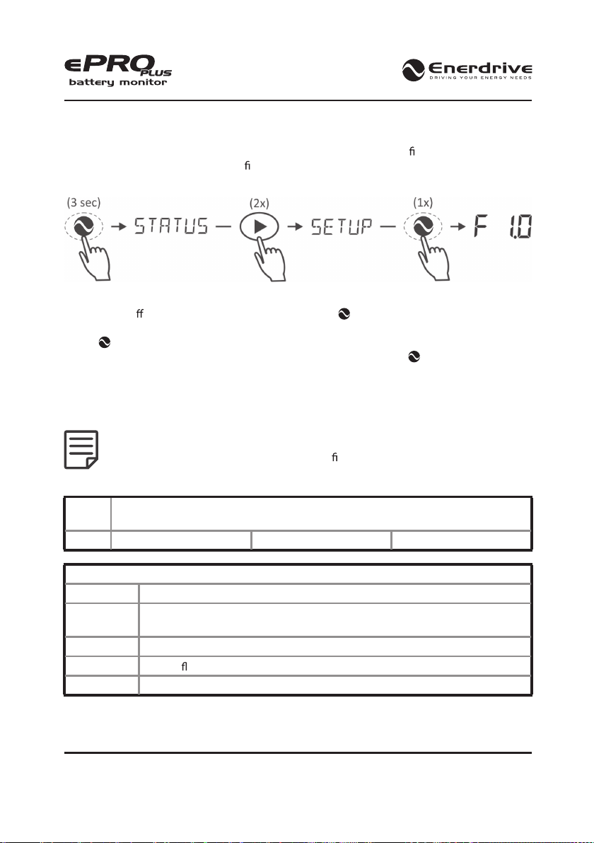
6. FUNCTION SETUP MENU
In the Function setup menu, your ePRO Plus can be adjusted further to t your needs. This menu
can only be entered after you have nished the initial Setup wizard. The following sequence
gives access to the Function menu:
When the Function setup menu is entered, you can use the left and right arrow keys to browse
through the di erent Functions. By pressing the MENU key, the selected Function value can
be viewed. The left and right arrow keys can now be used to change this value. Pressing the
MENU key again, will then step back to the Function menu. From any menu position, the
normal operating mode can be accessed again by pressing the MENU key for 3 seconds. This
will also save any Function value changes to internal memory. When no keys are pressed for 120
seconds while operating in the Function setup menu, the ePRO Plus will automatically return
to the normal operating mode again without saving any Function value changes. All available
Functions are described in the next chapters.
When the message ‘Locked’ appears on the display while trying to edit one of the
Functions, the ePRO Plus should be unlocked rst. See chapter 8 for more information.
6.1 Battery Bank 1 (Main) Properties
F1.0
Battery type. Choose the chemistry type of your battery. Table 7 shows the available
types.
Default: AGM Range: see table 7
Table 7
Battery type
Description
AGM
Typical deep cycle sealed lead acid battery with Absorbed Glass Matt
construction.
GEL Typical deep cycle sealed lead acid battery with ‘gelled’ electrolyte.
Flooded Typical ooded (wet-) lead acid battery.
LiFePO4
Typical Lithium iron Phosphate battery (does not apply to +B2 and +B3 inputs)

Enerdrive ePRO Plus Battery Monitor Owners Manual (Rev. 1.03)Page 20
F1.1 Battery capacity. Your Main battery’s capacity in Amphours (Ah).
Default: 200Ah Range: 10 – 10000Ah Step size: variable
F1.2 Nominal discharge rate (C-rating). The discharge rate (in hours) at which the battery
manufacturer rates your battery’s capacity.
Default: 20h Range: 1 – 20h Step size: 1h
F1.3
Nominal temperature. The temperature at which the battery manufacturer rates
your battery’s capacity.
Default: 20°C Range: 0 – 40°C Step size: 1°C
F1.4
Peukert’s exponent. Peukert’s exponent represents the e ect of reducing battery
capacity at higher discharge rates. When the Peukert value of your battery is unknown,
it is recommended to keep this value at 1.17. A value of 1.00 disables the Peukert
compensation and should be used for Lithium based batteries.
Default: 1.17 Range: 1.00 – 1.50 Step size: 0.01
F1.5 Reserved.
Default: - Range: - Step size: -
F1.6
Battery temperature. In this Function the average battery temperature can be adjusted
when no temperature sensor is connected. When a temperature sensor is connected,
the temperature readout in the Normal Operating Mode is enabled.
Default: 20°C Range: -20°C – 50°C Step size: 1°C
F1.7
Battery bank 1 name. Choose a display name for your battery bank that comes nearest
to your application.
Default: MAIN Range: see table 8
Table 8
Battery bank name Description
Bank 1 Battery bank 1
Bank 2 Battery bank 2
Bank 3 Battery bank 3
Main Main battery bank
Other manuals for ePro Plus
1
Table of contents
Popular Measuring Instrument manuals by other brands

MADDALENA
MADDALENA ElecTo SJ Instructions for installation, use and maintenance

Anton Paar
Anton Paar DMA 4100 M instruction manual

Stage6
Stage6 S6 instructions

Tektronix
Tektronix AWG70001B Installation and safety instructions

Tru-Test
Tru-Test XR3000 Pairing Instructions

LOVATO ELECTRIC
LOVATO ELECTRIC DME D100 T1 MID instruction manual


